Embedded Motion Control 2018 Group 3: Difference between revisions
| Line 157: | Line 157: | ||
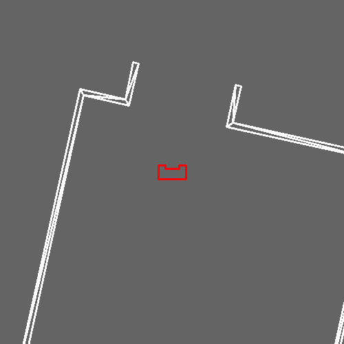
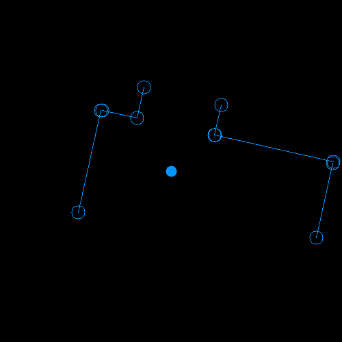
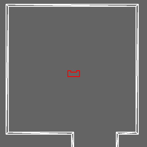
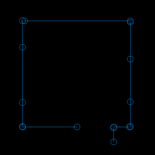
The code uses a split and merge algorithm to extract lines from laser data. This code was slightly modified to remove the ROS layer. | The code uses a split and merge algorithm to extract lines from laser data. This code was slightly modified to remove the ROS layer. | ||
[[File:Line_detection_Sim.png]] [[File:Line_detection_Lines.png]] | [[File:Line_detection_Sim.png|300px]] [[File:Line_detection_Lines.png]] | ||
====Angle Estimation==== | ====Angle Estimation==== | ||
Revision as of 09:30, 7 June 2018
Group Members
| TU/e Number | Name | |
|---|---|---|
| 0848904 | Luc (L.L.M.) van den Aker | l.l.m.v.d.aker at student.tue.nl |
| 0852908 | Thomas (T.) Neilen | t.neilen at student.tue.nl |
| 0909434 | Jeroen (J.W.) van de Valk | j.w.v.d.valk at student.tue.nl |
| 0896947 | Nourdin (N.) Kaai | n.kaai at student.tue.nl |
| 0883056 | Peter (P.) van Dooren | p.v.dooren at student.tue.nl |
| 0861750 | Ties (T.J.) van Loon | t.j.v.loon at student.tue.nl |
Initial Design
First off, the initial design itself is explained. After that, the report and presentation of it are shared.
Initial Design
Requirements
- PICO should make no collisions with any walls
- PICO cannot stand still for 30 seconds or longer
- For the escape room challenge, the robot should leave the room within 5 minutes
- For the hospital challenge, within 5 minutes, mapping, reverse parking and obtaining the object should be done
- Its surroundings should be made visible in a map
- PICO should be able to reach every position in the room
- PICO should be able to leave every room
- PICO should make distinction between the hall and rooms
- It should run autonomously, so in each challenge there should be no additional input
- To start your software, only one executable has to be called
- PICO should be able to recognize an object and stand still close to it
Functions
- PICO should be able to drive in any direction
- PICO should be able to turn around
- It should be able to detect walls
- PICO has to know its own position within the mapped map
- PICO is able to construct a map
- It should be possible to create a trajectory to a room
- PICO should be able to recognize an object
Components
- Sensors:
- Laser Range Finder (LRF)
- Wheel encoders (odometry)
- Actuator:
- Holonomic base (omni-wheels)
- Computer:
- Intel i7
- Ubuntu 16.04
Specifications
- Translation maximum: 0.5 m/s
- Rotation maximum: 1.2 rad/s
- Range of Laser Range Finder is assumed to be bigger than maximum room dimension
- The field of view of the Laser Range Finder is from -2 rad to 2 rad, divided in pieces of 0.004004
- The Laser Range Finder can only measure at one height
Interfaces
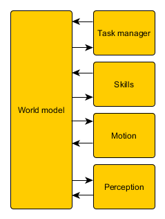
The interfaces of the initial design are shown here:
As shown in Figure 1, a world model is the link between all other parts. The tasks represent the highest level, meaning the most global work PICO has to do. The skills are needed to complete these tasks and some motions together form a skill. The perception contains the sensors, the continuous data. Below an overview of the different parts are given:
World model:
- Compose map
- Object recognition
Tasks:
- Mapping of the environment
- Backward parking at the specified location
- Searching for the object
Skills:
- Planning a trajectory
- Collision avoidance
- Backward parking
- Navigate
- Positioning in front of an opening
- Compose maps
Motion:
- Translation
- Rotation
Perception:
- Odometry
- Laser Range Finder
- Control effort
Report of Initial Design
Due to a misunderstanding, the report was not uploaded as a PDF yet. However, the full report was uploaded on this Wiki page (see below) before May 11th (17.00h), and now it is also uploaded as a PDF file (<1Mb). Our apologies for any inconvenience. The PDF of the report of the initial design can be found here: File:InitialDesign Group3 Report.pdf
Presentation of Initial Design
On May 16th, all groups presnted their initial design. So we also presented our initial design and included two GIFs of our process so far. A PDF of the slides can be found here: File:InitialDesign Group3 Presentation.pdf
Escape Room Challenge
Since our code to map a room was not finished completely, a new code for the Escape Room Challenge was made. This code was kept simple and effective. PICO should drive to a wall, turn to the left when it detects a wall within 0.4 meters from itself, and follow the wall (without hitting it of course). Then it will scan for a hallway to exit the room. When he sees a way to exit the room, PICO will go through the opening in the wall.
Our first attempt during the Escape Room Challange was very successful! PICO drove out of the room, but we were convinced he could do it even faster. So we set the speed higher for the second try, and it was even faster. PICO drove out of the room within 29 seconds. This resulted in a second place and being one of the two teams that made it out of the room.
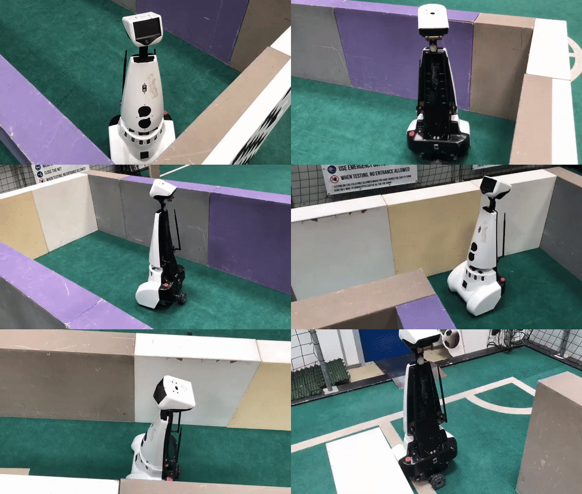
Here a shot video is shown of PICO leaving a room. Note that this is not filmed during the 'official' Escape Room Challenge. Due to our enthousiasm, we forgot to film, so we reconstructed the room during one of our test sessions.
Final Design
First off, the architecture is explained. After that, the presentation is shared.
Architecture
World Model
To build a map of the hospital a two fold mapping procedure will be used. First Pico will map the room it is currently standing in. The parameters of this room are then stored. Secondly a graph connecting all mapped routes with each other is build. By using this two level mapping abstraction it is easier to locate pico in a certain room. Also trajectory planning to a desired room can be more efficiently by using the graph.
The mapping of a room is done by scanning the environment using the laser range scanner. Through this data lines are fitted. By using these lines, a room is fitted, giving the dimensions of the room and the locations of the doors.
Line Extraction
A pre made laser line extraction algorithm was used, the source code can be found on: https://github.com/kam3k/laser_line_extraction
The code uses a split and merge algorithm to extract lines from laser data. This code was slightly modified to remove the ROS layer.
Angle Estimation
The odometry on PICO gives an estimate of the orientation of PICO. However due to the nature of odometry this estimate will drift over time. Therefore an absolute measurement of the angle is necessary. This is done using the lines extracted by PICO. The hospital is contructed of perpendicular lines. This allows the angle to be estimated modulo [math]\displaystyle{ 0.5 * pi }[/math].
A function was written which uses the lines from the line extraction to calculate the angle. The function does require an initial estimate of the angle to determine the general direction of the angle.
Merge Lines
To map a room pico needs to look 360 degrees around him, however the laser range finder only has a limited range. Therefore a PICO will scan lines, turn around 180 degrees and scan another time. It will then combine these two sets to end up with a set of lines which describe the entire room around PICO.
In the figures below the two sets of lines can be seen.
Fit Room
Once PICO has assembled a set of lines all around him he can determine the properties of the room he is in. This is done in two steps: First the dimensions of the room are found, then all the exits of the room are found.
Graph
Localization and Detection
Once a room has been mapped. PICO will be able to compare the detected lines to the map it has made. Based on this picos location can be determined.
Motion Control and Trajectory Planning
This part plans the trajectory PICO should take during the Hospital Challenge.
Approaching a Door
From the worldmodel PICO obtains his current position, and the position of the two corners of the door. A function is made which basically calculates a point right in the middle of the two corners, and puts a setpoint at a specified distance in front of the midpoint of the door. Using the PD-controller and the repulsion this setpoint can be reached by PICO.
Repulsion
A function is implemented which keeps PICO from touching the walls. This is done using virtual repulsion forces. The repulsion force is calculated using the reciprocal of the laser scan data. The laser data is scanned over the entire range of the sensor. For each sensor reading a repulsion force is calculated. By adding up all the repulsion forces over the entire scan range a single force vector is obtained. By putting this 'force' directly into PICO's speed input, it will have the tendency to drive away from walls. A tuning parameter has been made in the form of a maximum distance in which PICO can approach a wall. All laser data points which are larger than this value are set to 10 meters, to ensure that the walls closest to PICO deliver the most 'force'. A virtual force is added in places where PICO does not have any sensor readings. This force is also made using the 10 meter bias, to ensure that when PICO is not near any walls, the repulsion force equals zero.
PD-control
In order to have PICO move from point A to point B a simple PD-controller has been implemented. For testing purposes the PD-controller currently relies on odometry data. The 'error' is calculated by subtracting the current position from the target position. The 'derivative' of the error is calculated by simply subtracting the new error from the old one. The error is multiplied with a proportional action, while the derivative of the error is multiplied with a derivative action. During testing these parameters will be tuned to ensure optimal behavior of PICO.
PD + Repulsion
The speed outputted by the PD-controller and the speed generated by the repulsion function are simultaneously used in the PICO speed command. This means that, for example, when PICO is closing in on a corner, the speed (depending on the direction in which PICO is oriented) is temporarily reduced in the direction of the walls, ensuring that PICO gets enough clearance before returning on his path. A problem arises however when a setpoint is located directly behind a wall. In this case PICO cannot reach his goal, as the PD-controller 'pulls' PICO towards the setpoint, while the repulsion 'pushes' PICO away from the walls. Therefore it is necessary to give PICO setpoints which he can roughly 'see'. The generation of these setpoints is handled in one of the previous sections.
Task Manager
Parking
When the map building is complete, PICO has to park backwards to the wall behind the starting position. Parking is done upon touching the wall. After PICO parked, PICO should say: "I am parked!".
This is done by letting PICO drive forward to the starting position and stopping in front of the wall. Then PICO will turn around such that he can drive backwards to the wall. Since PICO cannnot scan what is behind him, a diffrent method is used to see/feel the wall he should touch. This is done using the control effort. If the control effort becomes large enough, PICO will stop since this increase in control effort is caused by touching the wall. All in all, a short video will summarize the result far better, so let's watch the parking skills of PICO:
Note that this is a GIF, so you can't hear PICO say "I am parked!".
Presentation of Final Design
Hospital Challenge
Still to come...
