Embedded Motion Control 2013 Group 1: Difference between revisions
| Line 105: | Line 105: | ||
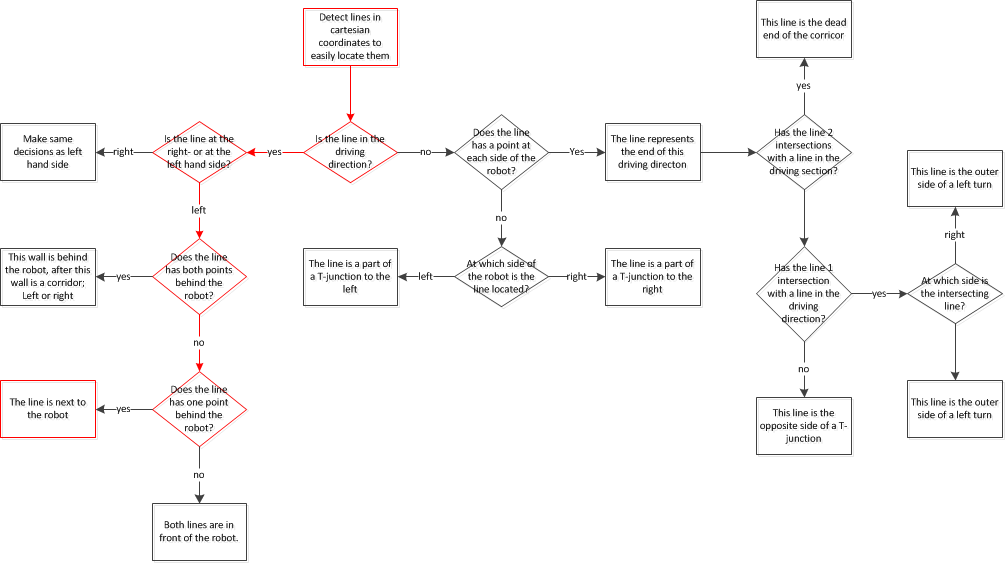
Flowchart of the situation node | Flowchart of the situation node | ||
Each end point can be of interest to map the current situation | Each end point can be of interest to map the current situation. | ||
[[File:flowchart situation.gif]] | [[File:flowchart situation.gif]] | ||
The situation node produces a message containing 3 boolean and one float32. | |||
The booleans represent possible drive direction, left, straight and right. | |||
The float32 contains the distance (in centimeters) to the first corner/T-junction or dead end. | |||
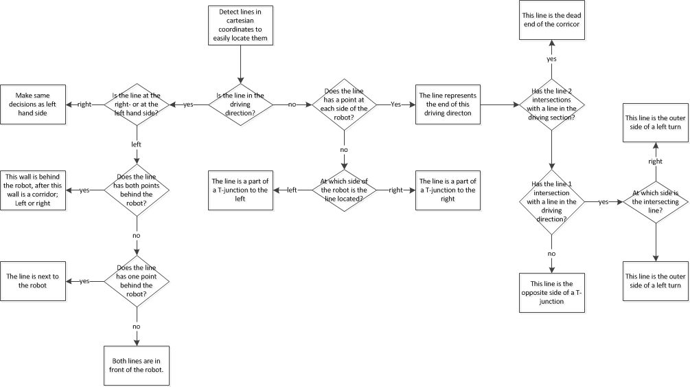
For the location node only 2 lines are | |||
For the location node only 2 lines are necessary (one left and one right) | |||
[[File:flowchart location.gif]] | [[File:flowchart location.gif]] | ||
The localisation node produces a message containing 2 float32. | |||
The first float32 represents the average angle (in degrees) of the 2 lines between which the robot is driving. | |||
(a value of zero means that the robot is driving straight through the corridor) | |||
This value is a input for the motion node to correct the driving angle | |||
The second float32 represents the distance (in centimeters) between the hart of the corricor (between the 2 detected lines) and the current position. | |||
(a value of zero means that the robot is driving in the middle of the corridor) | |||
This value is a input for the motion node to correct the driving position in the corridor | |||
The next assumptions are made for the localisation node: | |||
1: The robot needs to drive in between 2 walls | |||
2: The walls start behind the robot and continue in front of the robot | |||
3: When a turn is made, is should be around 90 degree, and the robot needs to drive in the corridor before localisation can be executed | |||
== Software architecture == | == Software architecture == | ||
Revision as of 12:19, 21 September 2013
Group Info
| Name: | Abbr: | Student id: | Email: |
| Groupmembers (email all) | |||
| Paul Raijmakers | PR | 0792801 | p.a.raijmakers@student.tue.nl |
| Pieter Aerts | PA | 0821027 | p.j.m.aerts@student.tue.nl |
| Wouter Geelen | WG | 0744855 | w.geelen@student.tue.nl |
| Frank Horstenbach | FH | 0792390 | f.g.h.hochstenbach@student.tue.nl |
| Niels Koenraad | NK | 0825990 | n.j.g.koenraad@student.tue.nl |
| Tutor | |||
| Jos Elfring | n.a. | n.a. | j.elfring@tue.nl |
Meetings
(Global) Planning
Week 1 (2013-09-02 - 2013-09-08)
- Installing Ubuntu 12.04
- Installing ROS Fuerte
- Following tutorials on C++ and ROS.
- Setup SVN
Week 2 (2013-09-09 - 2013-09-15)
- Discuss about splitting up the team by 2 groups (2,3) or 3 groups (2,2,1) to whom tasks can be appointed to.
- Create 2D map using the laser scanner.
- Start working on trying to detect walls with laser scanner.
- Start working on position control of Jazz (within walls i.e. riding straight ahead, turning i.e. 90 degrees).
- Start thinking about what kind of strategies we can use/implement to solve the maze (see usefull links).
Week 3 (2013-09-16 - 2013-09-22)
- Start work on trying to detect openings in walls.
- Start working on code for corridor competition.
- Continue thinking about maze solving strategy.
Week 4 (2013-09-23 - 2013-09-29)
- Decide which maze solving strategy we are going to use/implement.
Week 5 (2013-09-30 - 2013-10-06)
- To be determined.
Week 6 (2013-10-07 - 2013-10-13)
- To be determined.
Week 7 (2013-10-14 - 2013-10-20)
- To be determined.
Week 8 (2013-10-21 - 2013-10-27)
- To be determined.
Progress
Week 2
Flowchart of the situation node Each end point can be of interest to map the current situation.
The situation node produces a message containing 3 boolean and one float32. The booleans represent possible drive direction, left, straight and right. The float32 contains the distance (in centimeters) to the first corner/T-junction or dead end.
For the location node only 2 lines are necessary (one left and one right)

The localisation node produces a message containing 2 float32. The first float32 represents the average angle (in degrees) of the 2 lines between which the robot is driving. (a value of zero means that the robot is driving straight through the corridor) This value is a input for the motion node to correct the driving angle
The second float32 represents the distance (in centimeters) between the hart of the corricor (between the 2 detected lines) and the current position. (a value of zero means that the robot is driving in the middle of the corridor) This value is a input for the motion node to correct the driving position in the corridor
The next assumptions are made for the localisation node: 1: The robot needs to drive in between 2 walls 2: The walls start behind the robot and continue in front of the robot 3: When a turn is made, is should be around 90 degree, and the robot needs to drive in the corridor before localisation can be executed
Software architecture
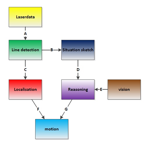
| Line: | Data type: |
| A | - |
| B | float-32 multi array (cart. points) |
| C | float-32 multi array (cart. points) |
| D | 3x boolean + 1 float32 |
| E | - |
| F | 2x float32 |
| G | - |

