Embedded Motion Control 2018 Group 6: Difference between revisions
No edit summary |
No edit summary |
||
| Line 101: | Line 101: | ||
== Requirements and specifications == | == Requirements and specifications == | ||
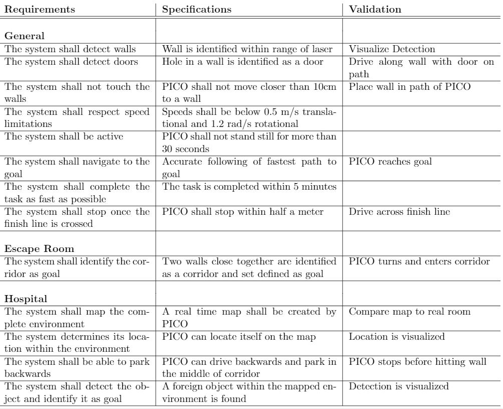
In the table below the requirements for the system and their specification as well as a validation are enumarated. | |||
[[File:Table1.JPG]] | [[File:Table1.JPG]] | ||
Revision as of 19:34, 10 May 2018
Group members
| Name: | Report name: | Student id: |
| Thomas Bosman | T.O.S.J. Bosman | 1280554 |
| Raaf Bartelds | R. Bartelds | add number |
| Bas Scheepens | S.J.M.C. Scheepens | 0778266 |
| Josja Geijsberts | J. Geijsberts | 0896965 |
| Rokesh Gajapathy | R. Gajapathy | 1036818 |
| Tim Albu | T. Albu | 19992109 |
| Marzieh Farahani | Marzieh Farahani | Tutor |
Initial Design
Requirements and Specifications
Use cases for Escape Room
1. Wall and Door Detection
2. Move with a certain profile
3. Navigate
Requirements for Escape Room
R1.1 The system shall detect walls without touching them
R1.2 The system shall detect the goal/door
R1.3 The system shall log and map the environment
R2.1 The system shall move slower than 0.5 m/s translational and 1.2 rad/s rotational
R2.2 The system shall not stay still for more than 30 seconds
R3.1 The system shall find the goal
R3.2 The system shall determine a path to the goal
R3.3 THe system shall navigate to the goal
R3.4 THe system shall not touch the walls
R3.5 The system shall complete the task within 5 minutes
Use cases for Hospital Room
(unfinished)
1. Mapping
2. Move with a certain profile
3. Orient itself
4. Navigate
Requirements and specifications
In the table below the requirements for the system and their specification as well as a validation are enumarated.
Functions, Components and Interfaces
The software that will be deployed on PICO can be categorized in four different components: perception, monitoring, plan and control. They exchange information through the world model, which stores all the data. The software will have just one thread and will give control in turns to each component, in a loop: first perception, then monitoring, plan, and control. Adding multitasking in order to improve performance considered, and might be applied in a later stage of the project. Below, the functions of the four components are described. What these components will do is described for both the Escape Room Challenge (ERC) and the Hospital Challenge (HC).
In the given PICO robot there exist two observers, a laser range finder (LFR) and an Odometry. The function of the LFR is to provide the detailed information of the environment through the beam of laser. The LFR specifications are shown in the table bellow,
| Specification | Values | Units |
| Detectable distance | 0.01 to 10 | meters [m] |
| Scanning angle | -2 to 2 | radians [rad] |
| Angular resolution | 0.004004 | radians [rad] |
| Scanning time | 33 | milliseconds [ms] |
At each scanning angle point a distance is measured with reference from the PICO. Hence an array of distances for an array of scanning angle points is obtained at each time instance with respect to the PICO.
The three encoders provides the odometry data (i.e) position of the PICO in x, y and &theta directions at each time instance. The LFR and Odometry observers' data plays a crucial role in mapping the environment. The mapped environment is preprocessed by two major blocks Perception and Monitoring and given to the World Model. The control approach to achieve the challenge is through Feedforward, since the observers provide the necessary information about the environment so that the PICO can react accordingly.
Perception:
Perception obtains sensor data in continuous time (i.e) the sampling rate of the LFR is maximum. Depending upon the state of the environment, the region of interest of LFR for observation is determined. The minimum distance calculated from this region is returned to the world model. This distance is accessed by other functional blocks for further processing.
ERC:
Input: LRF-data
Use:
- Process (filter) the laser-readings
Interface to world model, perception will store:
- Distances to all near obstacles
HC:
Input: LRF-data, odometry
Use:
- Process both sensors with gmapping
- Process (filter) the laser-readings
Interface to world model, perception will store:
- processed data from the laser sensor, translated to a map (walls, rooms and exits)
- odometry data: encoders, control effort
Monitoring:
Monitoring is a class entity that infers the state of the world model based on the current and previously stored LFR and Odometry data. Monitoring observes the environment at discrete time intervals (i.e) the sampling rate of the observers is less. The possible states from monitoring to the world model are as follows:
1.Start (Initialize and Verify the working of the observers)
2.Wall on Right
3.Wall on Left
4.Wall in front
5.Door on Right
6.Door on Left
7.Wall hit
8.Stop
The above mentioned states of the environment is conditionally assigned to the world model based on the observers' data.
ERC:
Input: distances to objects
Use:
- Process distances to determine situation: following wall, (near-)collision, entering corridor, escaped room
Interface to world model, monitoring will provide to the world model:
- What situation is occuring
HC:
Input: map, distances to objects
Use:
- Process distances and map to determine situation: following path, (near-)collision, found object
Interface to world model, monitoring will provide to the world model:
- What situation is occuring
Plan:
ERC:
Input: state of situation
Use:
- Determine next step: prevent collision, continue following wall, stop because finished
Interface to world model, plan will share with the world model:
- The transition in the statemachine, meaning what should be done next
HC:
Input: state of situation
Use:
- Determine next step: go to new waypoint, continue following path, prevent collision, go back to start, stop because finished
- Determine path to follow
Interface to world model, plan will share with the world model:
- The transition in the statemachine, meaning what should be done next
Control:
ERC:
Input: distances+angles to objects, state of next step
Use:
- Determine setpoint angle and velocity of robot
Interface to world model, what control shares with the world model:
- Setpoint angle and velocity of robot
HC:
Input: state of next step, path to follow
Use:
- Determine setpoint angle and velocity of robot
Interface to world model, what control shares with the world model:
- Setpoint angle and velocity of robot
Overview of the interface of the software structure:
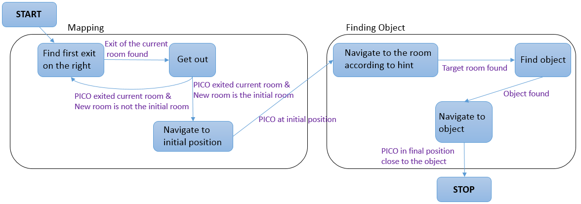
The diagram below provides a graphical overview of what the statemachine will look like. Not shown in the diagram is the case when the events Wall was hit and Stop occur. The occurence of these events will be checked in each state, and in the case they happened, the state machine will navigate to the state STOP. The state machine is likely to be more complex, since some states will comprise a sub-statemachine.

