Embedded Motion Control 2017 Group 10: Difference between revisions
| Line 121: | Line 121: | ||
=='' Challenge Result''== | =='' Challenge Result''== | ||
Pico managed to finish the corridor challenge in 24 seconds, this got us the third place. As can be seen in die video on the straight the Pico wobbles a lot this is due to the over reactive implementation of the potential field. Without this wobbling we would possible | Pico managed to finish the corridor challenge in 24 seconds, this got us the third place. As can be seen in die video on the straight the Pico wobbles a lot this is due to the over reactive implementation of the potential field. Without this wobbling we would possible be in the first place. | ||
[[File:Group10 coridor small.gif|thumb|center|600px|alt=interface diagram group 10|Corridor challenge result showing a drunk pico making a perfect corner.]] | [[File:Group10 coridor small.gif|thumb|center|600px|alt=interface diagram group 10|Corridor challenge result showing a drunk pico making a perfect corner.]] | ||
Revision as of 15:15, 17 June 2017
Group Members
| 0773865 | Tim Coerver |
| 0953808 | Pieter de Groot |
| 0970955 | Jos Terlouw |
| 0973811 | Bas Vermij |
| 0972391 | Roel Vromans |
| 0975718 | Corné van Haren |
Initial Design
Link to the PDF version of the design document: PDF
Requirements
- Software easy to setup
- Updated with one easy command, e.g. 'git pull'.
- Software can be compiled using 'cmake' and 'make'.
- One executable to start software.
- Autonomously solving the corridor challenge
- Solving the corridor challenge has to be done within 5 minutes.
- Autonomously solving the maze challenge
- Solving the maze challenge has to be done within 7 minutes.
- Avoiding collision
- Do not bump into walls or doors.
- Recognize and open a door in the maze
- There might be multiple dead ends in the maze, one of which is a door. The robot has to be autonomously open the door (by ringing a bell) to solve the maze.
- Detect corridors, corners, T-junctions and intersections
- The maze and corridor challenge consists of several, corridors, corners, T-junctions and intersections. Various algorithms created in order to detect these.
- Navigate through corridors, corners, T-junctions and intersections
- When corridors, corners, T-junctions and intersections are detected, the robot has to drive trough these. In order to do this, strategies have to be created for each of these.
- Detecting dead ends
- The maze can contain dead ends, these have to be distinguished from doors.
- Detecting maze exit
- The exit of the maze has to be detected in order to know when the maze is finished.
- Navigate open spaces
- The maze can contain open spaced, when these are detected these has to be explored by navigating trough them.
Specifications
The specifications are related to the requirements specified above.
- The time to reach the end of the maze is 7 minutes.
- The time to accomplish the corridor challenge is 5 minutes
- The robot may not be idle for more than 30 seconds.
- When the robot find a door, it rings a bell and the door will be opened manually.
- Two attempts to solve the maze are allowed. Both attempts have to be finished within 7 minutes total.
- Two attempts are allowed to solve the corridor challenge. Both attempts have to be finished within 5 minutes.
- When the robot bumps into a wall the attempt is over.
Specifications of the maze
- All walls are positioned approximately perpendicular to one another.
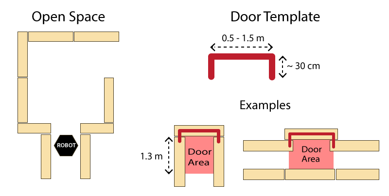
- Open spaces might occur (as depicted in Figure 1 ).
- There may be loops in the maze, which means that some walls may not be connected to other walls.
- Walls are approximately parallel.
Doors and open spaces are specified as described by Figure 1.
Functions
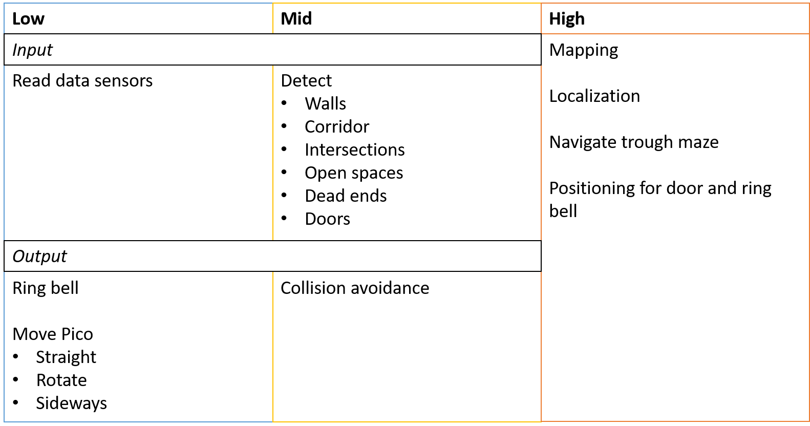
The functions are categorized in three different levels of complexity: Low, Mid and High level. An overview of the functions is given in Figure 2.
Components
The following components are accessible on the pico:
- Sensors
- Laser Range Finder (LFR)
- Wheel encoders (odometry)
- Actuators
- Holonomic Base (Omni-wheels)
- Computer
- CPU Intel i7
- OS Ubuntu 14.04
Interface
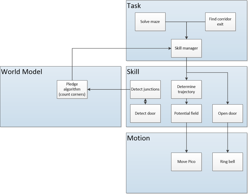
The interfaces between functions are shown in Figure 3. Here the functions are devided into: Tasks, Skills, Motion and World Model. The world model contains the functions that are used to keep track of Pico's surrounding. Tasks contains the functions on the highest level where the robot decides what it is going to do, like solve the maze. The skill block consists of all functions that make the robot perform lower level tasks such that the high level objective can be achieved. The motion block does the low level operations that make the skill functions work.
The Corridor Challenge
Potential field
Corner mapping
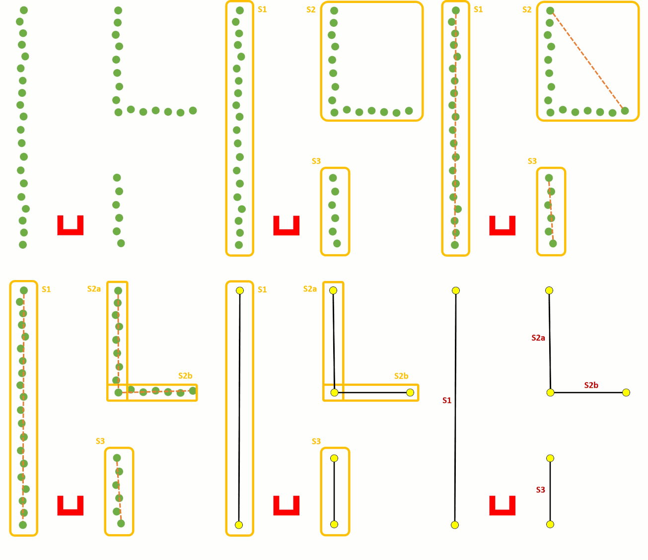
To detect corners and walls the Split and merge algorithm is used on the laser data. This algorithm contains the following procedure;
- 1. Laser data is transformed in x and y coordinates
- 2. The laser data points will split in segments
- 3. Within each segment the points between the first and last point will be check for the distance perpendicular to the line between the first and last point
- 4. If the maximum perpendicular point is above a set threshold (0.2 m), this point will set as a vertex within this segment.
- 5. Step 3 and 4 will be repeated until there are no new vertices are found.
- 6. Within each segment a line will be defined using the least squire method.
- 7. If two lines are connected with each other, the intersection will be used to define the vertex.
- 8. If there is not a connection with another line, the end point will be fitted on the line.
These steps are visualized in the figure below:
Challenge Result
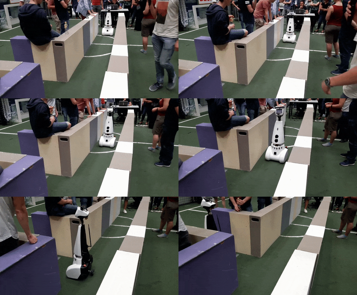
Pico managed to finish the corridor challenge in 24 seconds, this got us the third place. As can be seen in die video on the straight the Pico wobbles a lot this is due to the over reactive implementation of the potential field. Without this wobbling we would possible be in the first place.
The Maze Challenge
Final design
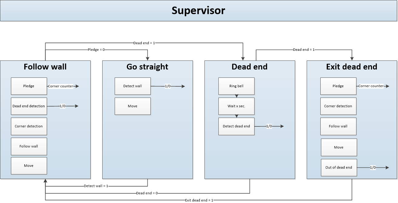
For the final desig the following stage machine is designed
Pledge
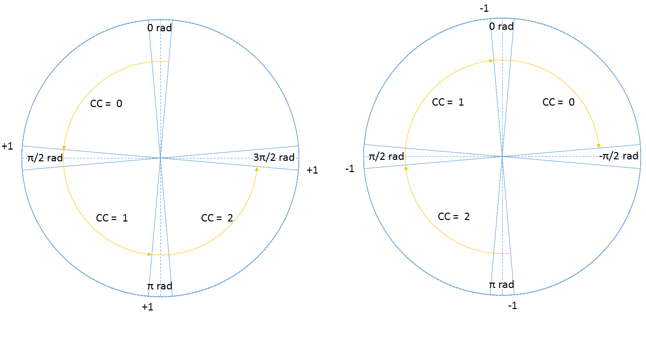
The Pledge algorithm is used to make a very simplistic global world map to solve the maze. The pledge algorithm uses relative angle movements to calculate the total rotation angle of the robot. Rotation clockwise has negative angle and rotation clockwise has positive angle. After the robot rotates pi rad, the OdometryData switches to a negative angle of -pi rad. The relative angle is in that case 2 pi rad. To compensate, 2 pi is subtracted leaving with only the relative angle. With this rotated angle, the taken corners can be calculated.
To make the pledge algorithm robust, a method is used where a corner is counted after the robot moved pi/2-delta rad and will hold this count till the robot moved another pi/2-delta rad as shown in Figure 5 (left circle). In between the robot can move freely without corners being added. The same holds for the robot rotating back where the corner counter is reduced only after the robot moved -pi/2+delta rad Figure 5 (right circle).
Dead end detection
The dead end detection method makes use of the Corner mapping method as described above.
The corner mapping returns the vertices's of the line segments it has found, and if the vertices's are connected to each other. This information is used by the corner detection to form vectors between these vertices's.
These vectors are then normalized so they can be used to determine the angle between them. If two vectors are connected, the angle is calculated using the following function

Where [math]\displaystyle{ \theta }[/math] is the angle between the vectors and vi • vi+1 is the inner product of vector i with i+1. If this angle is 90±5 degrees, the corner is marked perpendicular. The calculated angle does not give information on the sign. A vector pointing to the left or right result in the same angle (as the inner product between almost perpendicular vectors is approximately 0). In order to determine the direction of the turn, the vector vi is rotated 90 degrees to the left, using a rotation matrix. The inner product is then calculated again, if the result is positive, then the turn is to the left. If rotating the vector to the right results in a positive inner product, then the turn is to the right. All vectors are checked in this fashion, resulting in a list of left-, right- or no-turns, describing all corners visible to the robot.
Using the list of turns, possible dead ends can be identified. An important aspect of the list of vertices's is that it is generated in an anti clockwise direction. Therefore it is known that when two left turns follow after each other indicate a dead end candidate. Since the walls of the dead end candidate can be long, and therefore can just be a wall in the maze, further identification is done. The specifications of a dead end are given in the specifications above. There it is noted that the width of the dead end has to be within (0.5 < width < 1.5) [m]. So when a possible dead end is found, the width of that dead end candidate is checked. If it fails, the dead end is dropped. If it passes the minimum depth of 0.3 [m] is checked. If that also passes the dead end will be marked.
As all turns in the turn vector have been evaluated, the dead end closest to pico is returned from the dead end detection method for furher use in the state machine.
Matrix multiplication, matrix norms and inner products where used in this function to make the implementation easier. Here fore the Eigen library was used, this made working with matrices a lot more convenient (almost matlab like). The implementation of the function is found on git dead end detection
Result
After the mild succes at the corridor challenge, where we finished 3th. As we had to use code that was not tested in practice, the speed was not good enough for first place.
After the corridor challenge, where we relied heavily on potential field, a complete overhaul of our approach was made. We decided to use potential field only for obstacle avoidance, when all our other strategies failed. So for the primary motion skill, the follow wall procedure was created. This makes use of the laser data in a smarter way such that speed could be increased (as no obstacles had to be avoided, only walls had to be followed). This combined with the robust implementation of pledge ment that solving a maze was not the problem.
As we had code that was able to detect walls, that could than be converted to vectors, used to identify angles between walls. We where able to detect wall sections that form dead ends. After matching these to a templates, a robust and reliable procedure to detect dead ends was added to the general maze solving algorithm. The only task left was the ringing of the bell to open the door.
When we first tested this maze solving program, the day before the challange, we where amazed by the robustness of our code. All scenarios made up by us where solved by the robot. Walls where followed, loops in the maze where navigated correctly, dead ends where found and doors where opened. All good.
The day of the challenge
As we where the last group to have a go at the challenge, the time to beat was set. 2:43 minutes. Good progress was made by pico, the door was found and opened. The only task left was finding the exit. This was also looking good. We had enough time on the clock to become first. Pico found the exit, 2:05 on the clock. With the finish line in sight (20 cm). Pico decided to stall and trow a segmentation error. Resulting in a 3th place, again.
It is unclear to us where the fault came from. A possible cause might be that the net hanging close to the exit of the maze gave some strange environment we did not take into account when we where testing. But we do not know what part of our code was unable to deal with this situation.