Embedded Motion Control 2017 Group 9: Difference between revisions
| Line 44: | Line 44: | ||
<!-- --> <!-- White space --> | <!-- --> <!-- White space --> | ||
= Initial Design = | |||
The initial design for the maze challenge is elaborated below. It includes the requirements, functions, components, schematic of program structure, specifications and interfaces to define the working of PICO. The file for the initial design is included here: | The initial design for the maze challenge is elaborated below. It includes the requirements, functions, components, schematic of program structure, specifications and interfaces to define the working of PICO. The file for the initial design is included here: | ||
[[File:Assignment-for-week1.pdf]] | [[File:Assignment-for-week1.pdf]] | ||
== Requirements == | |||
➢ PICO drives autonomously through maze<br> | ➢ PICO drives autonomously through maze<br> | ||
➢ Being able to take a turn without touching a wall<br> | ➢ Being able to take a turn without touching a wall<br> | ||
| Line 58: | Line 58: | ||
➢ Being able to recognize the door<br> | ➢ Being able to recognize the door<br> | ||
== Functions == | |||
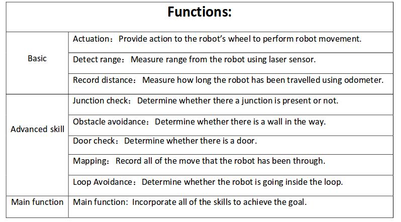
[[File:Functionsg9.jpeg]] | [[File:Functionsg9.jpeg]] | ||
== Components == | |||
'''drive control''' <br> | '''drive control''' <br> | ||
‐Holonomic base (omni‐wheels) <br> | ‐Holonomic base (omni‐wheels) <br> | ||
| Line 76: | Line 76: | ||
<br> | <br> | ||
== Specifications == | |||
- maximum translational speed of 0.5 m/s <br> | - maximum translational speed of 0.5 m/s <br> | ||
‐ maximum rotational speed of 1.2 rad/s <br> | ‐ maximum rotational speed of 1.2 rad/s <br> | ||
| Line 85: | Line 85: | ||
[[File:Doortempg9.jpeg]] | [[File:Doortempg9.jpeg]] | ||
== Interfaces == | |||
The odometer and LRF generates data for mapping the environment. <br><br> | The odometer and LRF generates data for mapping the environment. <br><br> | ||
The algorithm sets nodes on the junction as a setpoint for navigation, plans the route and put the actuators to work accordingly. <br><br> | The algorithm sets nodes on the junction as a setpoint for navigation, plans the route and put the actuators to work accordingly. <br><br> | ||
The odometer and LRF keeps on keeping track of the environment and the software recognizes obstructions, dead ends that might be doors and junction. | The odometer and LRF keeps on keeping track of the environment and the software recognizes obstructions, dead ends that might be doors and junction. | ||
= Corridor challenge = | |||
== design == | |||
== result and evaluation of the challenge == | |||
= Maze challenge = | |||
== design == | |||
== result and evaluation of the challenge == | |||
Revision as of 20:45, 8 June 2017
Group Members
| Name: | Student id: |
| Mian Wei | X |
| Zhihao Wu | X |
| Petrus Teguh Handoko | X |
| Bo Deng | X |
| Bo Cong | X |
| Jian Wen Kok | X |
| Nico Huebel | Tutor |
Initial Design
The initial design for the maze challenge is elaborated below. It includes the requirements, functions, components, schematic of program structure, specifications and interfaces to define the working of PICO. The file for the initial design is included here: File:Assignment-for-week1.pdf
Requirements
➢ PICO drives autonomously through maze
➢ Being able to take a turn without touching a wall
➢ Being able to detect a turn or branching corridors
➢ Avoiding collisions with obstacles (including the walls)
➢ Driving straight and rotating smoothly
➢ PICO should not stand still for 30 seconds
➢ Avoid getting trapped in a loop of the maze
➢ Being able to recognize the door
Functions
Components
drive control
‐Holonomic base (omni‐wheels)
‐Pan‐tilt unit for head
detection
‐170◦ wide‐angle camer
‐Laser Range Finder (LRF)
‐Wheel encoders (odometry)
‐Asus Xtion Depth sensor
world model
computer
‐Intel I7
‐Ubuntu 14.04
Specifications
- maximum translational speed of 0.5 m/s
‐ maximum rotational speed of 1.2 rad/s
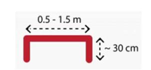
‐ Door template: length of 0.5 ‐ 1.5m and with side walls of approximately 30cm, see figure below
‐ LRF accuracy and range unknown
‐ odometer accuracy unknown
Interfaces
The odometer and LRF generates data for mapping the environment.
The algorithm sets nodes on the junction as a setpoint for navigation, plans the route and put the actuators to work accordingly.
The odometer and LRF keeps on keeping track of the environment and the software recognizes obstructions, dead ends that might be doors and junction.

