Viotar/Hardware Design: Difference between revisions
| Line 93: | Line 93: | ||
The needed motor power is calculated using <math>P=M_{T}\cdot\Omega</math>. For this, the total load <math>M_{T}</math> and the angular speed <math>\Omega</math> have to be calculated. | The needed motor power is calculated using <math>P=M_{T}\cdot\Omega</math>. For this, the total load <math>M_{T}</math> and the angular speed <math>\Omega</math> have to be calculated. | ||
The total motor load consists of the load coming from the friction of the bowing belt with the string <math>M_{ | The total motor load consists of the load coming from the friction of the bowing belt with the string <math>M_{bt}</math> and the friction of the bearing supporting the wheel that drives the belt, <math>M_{br}</math>. | ||
<math>M_{bt}</math> is calculated by <math>M_{w}=R\cdot F_{w,bt}=R\cdot F_{n}\cdot\mu_{w,bt}</math>, with <math>F_{n}=F_{b}</math> the normal force between the bowing belt and the string. This bow force has a maximum of <math>4 N</math>. The value of <math>\mu_{w,bt}</math> is estimated at a rather high <math>0.7</math>. The radius <math>R</math> at which the belt runs around the shafts is taken to be <math>7.5 mm</math>, on the actual design it will be smaller than this. This yields <math>M_{bt}=21.0 mNm</math>. | |||
<math>M_{ | <math>M_{br}</math> is calculated assuming cylindrical roller bearings will be used. For cylindrical roller bearings <math>M_{br}=F\mu_{w,br}d/2</math>, with <math>mu_{w,br}=0.002</math> the friction coëfficient for cylindrical roller bearings, <math>F</math> the lateral force on between the bearing and the shaft which is estimated at <math>30 N</math>, and <math>d</math> the shaft diameter, which is about <math>4 mm</math> for a bearing with a outer diameter of <math>11 mm</math>. This yields <math>M_{br}=0.12 mNm</math>. | ||
<math> | The angular speed of the motor shaft <math>\Omega</math> is determined to be <math>\Omega=v_b/R=2546 rpm</math>, with bow speed <math>v_b</math> the maximum occuring value, and <math>R</math> the radius at which the belt runs. | ||
Now combining the findings for <math>M_{bt}</math> and <math>M_{br}</math>, the total motor load <math>M_{T}</math> is estimated at <math>21.12 mNm</math>. The power then becomes <math>P=5.63 W</math> | |||
Geeft als schatting van de ordegrote: | Geeft als schatting van de ordegrote: | ||
Revision as of 12:43, 20 January 2011
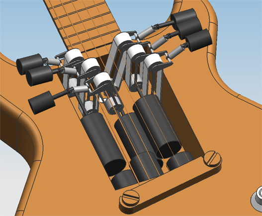
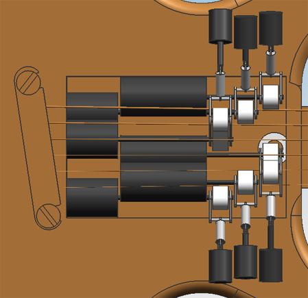
Hardware designDesign 0.1On friday the 5th of november, the first attempt at a design was finished. Only geometric constraints were taken into account, meaning the size of the engines and actuators were solely adjusted to the amount of space that was available in the guitar.
Design 0.2From reviewing design 0.1 with the group, the following points of improvement were determined:
These improvements have been worked into design 0.2.
Design 0.3 to 0.6Estimation of the required motor powerThe needed motor power is calculated using [math]\displaystyle{ P=M_{T}\cdot\Omega }[/math]. For this, the total load [math]\displaystyle{ M_{T} }[/math] and the angular speed [math]\displaystyle{ \Omega }[/math] have to be calculated. The total motor load consists of the load coming from the friction of the bowing belt with the string [math]\displaystyle{ M_{bt} }[/math] and the friction of the bearing supporting the wheel that drives the belt, [math]\displaystyle{ M_{br} }[/math]. [math]\displaystyle{ M_{bt} }[/math] is calculated by [math]\displaystyle{ M_{w}=R\cdot F_{w,bt}=R\cdot F_{n}\cdot\mu_{w,bt} }[/math], with [math]\displaystyle{ F_{n}=F_{b} }[/math] the normal force between the bowing belt and the string. This bow force has a maximum of [math]\displaystyle{ 4 N }[/math]. The value of [math]\displaystyle{ \mu_{w,bt} }[/math] is estimated at a rather high [math]\displaystyle{ 0.7 }[/math]. The radius [math]\displaystyle{ R }[/math] at which the belt runs around the shafts is taken to be [math]\displaystyle{ 7.5 mm }[/math], on the actual design it will be smaller than this. This yields [math]\displaystyle{ M_{bt}=21.0 mNm }[/math]. [math]\displaystyle{ M_{br} }[/math] is calculated assuming cylindrical roller bearings will be used. For cylindrical roller bearings [math]\displaystyle{ M_{br}=F\mu_{w,br}d/2 }[/math], with [math]\displaystyle{ mu_{w,br}=0.002 }[/math] the friction coëfficient for cylindrical roller bearings, [math]\displaystyle{ F }[/math] the lateral force on between the bearing and the shaft which is estimated at [math]\displaystyle{ 30 N }[/math], and [math]\displaystyle{ d }[/math] the shaft diameter, which is about [math]\displaystyle{ 4 mm }[/math] for a bearing with a outer diameter of [math]\displaystyle{ 11 mm }[/math]. This yields [math]\displaystyle{ M_{br}=0.12 mNm }[/math]. The angular speed of the motor shaft [math]\displaystyle{ \Omega }[/math] is determined to be [math]\displaystyle{ \Omega=v_b/R=2546 rpm }[/math], with bow speed [math]\displaystyle{ v_b }[/math] the maximum occuring value, and [math]\displaystyle{ R }[/math] the radius at which the belt runs. Now combining the findings for [math]\displaystyle{ M_{bt} }[/math] and [math]\displaystyle{ M_{br} }[/math], the total motor load [math]\displaystyle{ M_{T} }[/math] is estimated at [math]\displaystyle{ 21.12 mNm }[/math]. The power then becomes [math]\displaystyle{ P=5.63 W }[/math] Geeft als schatting van de ordegrote: M_r=30*0.002*4/2=0.12Nmm Aangezien de lagers een straal hebben van nooit meer dan 10mm word de wrijvingskracht in de lagers nooit hoger dan 1 [N]. Voor 2 lagers komt de absoluut maximale kracht dan op 2 [N]. De totale kracht die de motor dan moet kunnen leveren is dan ongeveer gelijk aan 16[N], dit is dan wel de kracht bij stationair toerental. Rotatie-energie lager: E=1/2 J_z (φ^2 ) ̇,J_z=1/2 mr^2 geeft samen:E=1/4 mr^2 (φ^2 ) ̇=1/4*0.0017*〖0.01〗^2*300*2*π=8*〖10〗^(-5) Dat is dus niet heel veel (een lager weegt 0.0017 kg volgens skf). M_w=3.2*10=32Nmm,M_tot=32+0.12=32Nmm P=M_T∙Ω=0.032*300=10 W
Picking a motorPicking an actuatorIn the hardware design, six actuators are needed in order to push the bowing belt onto the string. These actuators have to be able to push with at least 4 Newton of force onto the belt. We also want the Viotar to be able to play 16 notes per second, so the actuator has to be fast two. After some research a hybrid linear actuator, made by Haydon, was found, a 21000 series size 8 linear actuator, to be precise. This actuator is not only very small, 21 mm square by 33 mm, but it is also powerful and fast enough to do the job. It can deliver up to 44 Newton of thrust and can travel at more than 50 mm/sec, depending on the thrust. Space between stringsDesign 0.6overwegingen over dat rechte stuk in de klauw zodat er geen moment op komt de CAD FEM berekeningen voor de stijfheid van de klauwen
uberhaupt waarom er direct drive is gekomen, helemaal boven bij design 0.2 Right-hand user interfaceRequirementsAs the exciting of the strings is done by actuators and motors, there must be a way the player can control what these actuators and motors do. While the player has his left hand busy fretting the strings, his right hand should tell the instrument what strings to play, and how loud te play them at any given time. Below are the most important product requirements that apply to this part of the instrument.
Two main concepts were conceived for this right-hand user interface. Turning handgripThe right hand holds on to a handgrip that can turn around the axis that coïncides with the player's forearm. Turning the hand around this axis comes very naturally to most people and can be done very fast with little tension. Turning this handgrip around this axis controls the bowing speed. Turning the grip counterclockwise makes the bowing belts go in counterclockwise direction. The further the grip is turned away from its initial position, the more intense the note. The same goes for clockwise direction. When the grip is in neutral position, the bowing belts stand still (but stay in contact with the string, damping it). Because the required turning movement of the hand is so natural, Requirement 3 and 4 of the above list can be met. Additionally, the grip is fitted with 6 ergonomically placed buttons (like on a computer mouse, for instance), each corresponding to it's own string. Holding down a button places the bowing belt on the string, releasing it moves the bowing belt away from the string. Although the player has only 5 fingers Requirement 1 on the above list is still met, because the thumb can control 2 buttons by 'rolling' over them. Pressure sensitive keysThere are 6 pressure sensitive keys, each corresponding to a string. Holding a key down will place the bowing belt on the string, releasing a key will move the bowing belt away from the string. While the key is pressed down, the amount of pressure the user applies on the key defines the note intensity. The keys will be long (like spacebars on a laptop), so that the thumb and index-/middlefinger can alternate while tapping on them, making it possible to meet Requirement 3 and 4 in the above list. RealisationDue to lack of time and financial resources, the choice has fallen on the pressure sensitive keys concept. This may be realised in two ways.
The first option is the easiest as MIDI keyboards are already complete devices that only need to be plugged into the computer. As this project turns out to be more of a proof of concept than the building of a final product, the MIDI keyboard doesn't have to be demolished so that it has only 6 keys, and fit onto the guitar. Instead, the only thing that needs to be done is to let the keyboard communicate with SIMULINK. Searches on how to do this on the internet didn't raise any answers on this, however. Therefore, the laptop spacebar alternative is examined. It should be noted that, for this purpose the laptop key intuitively seems more fitting than the keyboard key. For instance, the laptop key can me tapped much faster while after each tap it is able to retract fully, while a keyboard key needs more time for this, which puts a limit on how fast you can play on a single string. Also, the laptop spacebar has a (for the user) more discrete "on" and "off" position, because there is some sort of treshold in it that makes it avoid the halfway-pressed-down position. This way the player has a clearer idea when the bowing belts are on and off the strings. It is not possible to order a completely working seperate spacebar. Instead, you can only buy seperately the upper part of the spacebar, the mechanisms that hold it in position and allow it to move merely up and down, and the on-off sensor. Each of our spacebars each need a mounting too, so the only solution is to buy multiple laptop keyboards and literally saw the part with the spacebar out. Placing the pressure sensors underneath the spacebars is very easy, because there is enough flat surface on the mounting under the bars to glue these on. Placing stickers on the bottom side of the spacebar can make sure the spacebar touches the pressure sensor just enough. |
