Embedded Motion Control 2017 Group 1: Difference between revisions
Jump to navigation
Jump to search
| Line 52: | Line 52: | ||
# Maze challenge: The robot should drive through a maze and find the exit. | # Maze challenge: The robot should drive through a maze and find the exit. | ||
=== Requirements === | === Requirements/Specifications === | ||
| Line 165: | Line 165: | ||
## Intel I7 | ## Intel I7 | ||
Revision as of 13:48, 9 May 2017
Group Members
| Name: | Student id: |
| Karel van de Plassche | 0653197 |
| Joey Hendriks | 0773023 |
| Ioannis-Dionysios Bratis | 0978560 |
| Jad Haj Mustafa | 0979428 |
| Jip Reinders | 0853301 |
| Juliana Langen | 0617062 |
| Yanick Douven | Tutor |
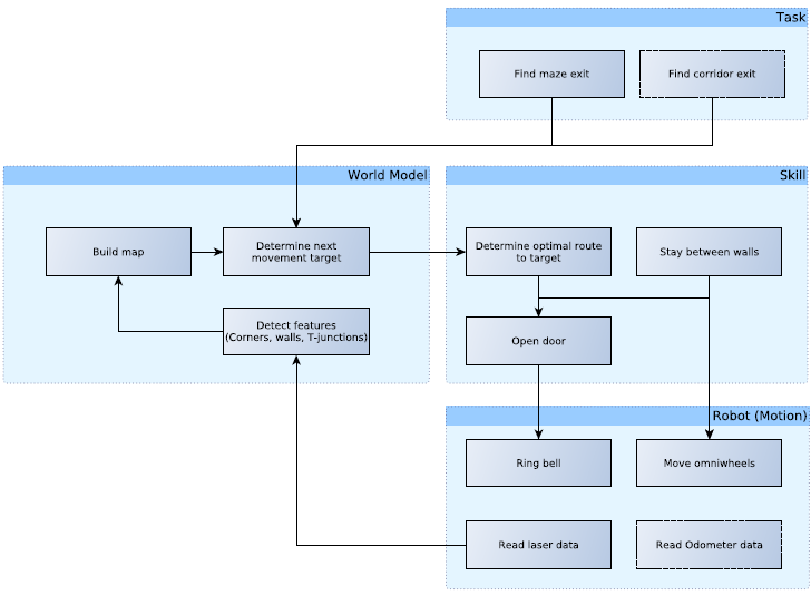
Initial Design
Link to file: PDF
Overview
In this article a summary of the embedded software design is presented.This software is used to solve the following problems:
- Corridor challenge: The robot should drive through a corridor and take the first exit.
- Maze challenge: The robot should drive through a maze and find the exit.
Requirements/Specifications
Functions
| Function | Description | |
|---|---|---|
| Low-level | initialize | Initialize actuators |
| readSensors | Read the odometer and laser data | |
| turnLeft | Turn 90° left | |
| turnRight | Turn 90° right | |
| turnAround | Turn 180° | |
| stopMovement | Stop omniwheels | |
| driveForward | Accelerate or decelerate | |
| driveBackward | Drive backward | |
| driveLeft | Move left | |
| driveRight | Move right | |
| ringBell | Ring the bell of the door. | |
| Mid-level | detectWall | Detect a wall (~30cm) |
| detectCorner | Detect a corner (crossing of two walls) | |
| detectDeadEnd | Detect a dead end | |
| detectFinish | Detect the finish line | |
| detectOpenSpace | Detect an open space | |
| detectOpenWorld | Detect if in the open world (like the maxe exit) | |
| detectTJunction | Detect a T-junction (where three corridors meet) | |
| detectCrossing | Detect a crossing (where the four corridors meet) | |
| shutDown | Terminate robot, if required | |
| checkDoor | Send a signal and wait x seconds | |
| chooseCorridor | Choose which corridor to take | |
| High-level | stayBetweenWalls | Stay in the center of two walls |
| createMap | Build map of surroundings | |
| trackPath | track the path through the map | |
| detectLoop | Detect a loop in the maze | |
| detectStack | Detect if stuck | |
| optimalDecision | Decide next move based on given algorithm |
Components
The PICO robot consists of multiple components which are listed below:
- Sensors:
- Laser Range Finder (LRF): Through the LRF on the PICO one can detect the distance to an object.This is accomplished by sending a laser pulse in a narrow beam towards the object and measuring the time taken by the pulse to be reflected on the target and returned to the sender.
- Wheel encoders (odometry): Through the encoder one can obtain the speed of the wheels which can be used to control PICO based on the provided data.
- Actuators:
- Holonomic base (omni-wheels)
- Pan-tilt unit for head
- Computer
- Ubuntu14.04
- Intel I7
