PRE2016 3 Groep15: Difference between revisions
| Line 331: | Line 331: | ||
[1] http://www.home-building-answers.com/house-foundations.html | [1] http://www.home-building-answers.com/house-foundations.html | ||
[2] https://www.asme.org/engineering-topics/articles/construction-and-building/made-in-japan-earthquake-proof-homes | [2] https://www.asme.org/engineering-topics/articles/construction-and-building/made-in-japan-earthquake-proof-homes | ||
[3] https://theconstructor.org/earthquake/earthquake-resistant-techniques/5607/ | [3] https://theconstructor.org/earthquake/earthquake-resistant-techniques/5607/ | ||
Revision as of 17:53, 29 March 2017
Group Members
| Name | Student ID |
| Martijn de Boer | 0907480 |
| Josja Geijsberts | 0896965 |
| Gijs Herings | 0953862 |
| Martin van Leeuwen | 0901497 |
| Max van Meer | 0951669 |
| Bart Tulkens | 0956335 |
Introduction
In the construction sector, building is still largely manual labor or aided by tools, but not automated. Some companies have tried to automate building construction by 3D printing layers of cement. This however, is not the only or the best solution. Pouring cement in this way generally leads to it not being reinforced concrete. If prefab components are grabbed and stacked to build a construction, electronics and piping can be built into the construction easily.
In this wiki page, a solution for an automated construction robot which places prefabricated building blocks, its advantages and disadvantages and how this can be achieved will be explained. The first idea was to build a simplified prototype, which used Duplo blocks to autonomously build. However, after thorough planning and analysis, this plan was discontinued. The main reason was that this solution would be too time consuming and the other aspects of this project would receive too little attention. A new plan was developed, with a new goal. The new goal is to develop a functioning simulation with a user-friendly interface. Alongside the simulation, a detailed model will also be made. To achieve this goal, a couple experts in construction discipline will be contacted
Basics of House Building
For every house, four things always need to be present; the foundation, walls, windows and a roof. Because of the focus of this project on society as explained later on, only the most simple en effective building methods are given. Another aspect that has to be taken into account when building a house or district is the availability of water, electricity, waste collection and a proper sewerage. These basic essentials will also discussed below.
Foundation
The base of a house is called a foundation. Everything will be built on top of the foundation. The foundation should be stable in all conditions and create an even surface to build on. There are different types of foundations, which are used under different conditions. For example, in an area with a high change on earthquakes, a different type of foundation is used. Below, the most common foundations are elaborated. [1]
- Masonry foundation: A foundation made of concrete or bricks that creates a perimeter wall. Inside of these walls, piers, columns and posts can be placed. [1]
- Concrete foundation: This foundation is made by creating a mold for the concrete and after the drying process of the concrete, a solid foundation is created on which can be build. The concrete is reinforced by iron bars most of the time. This is one of the most common used foundations in the U.S.A. and Europe, certainly when a basement is created. [1]
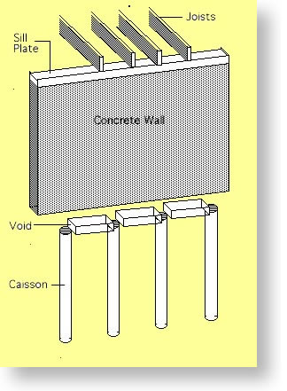
- Caisson foundation: In certain areas, the soil contains particles like clay, which expands when exposed to moisture. Normal foundations will break under the pressure created by the expansion. Caisson foundations are the solution for this problem. The foundation consist of multiple piles or posts that are embedded in the underlying bedrock, to transfer the weight. On top of this, a normal concrete foundation is added. Figure 2 visualizes this concept. [1]
- Wood foundation: A less durable, but cheaper and faster to build foundation. [1]
- Pile foundation: This type caisson of foundation is mostly used when there is a higher change on floods. Piles are driven into the ground to support the load on deeper layers of the soil. The house will rest on top of this piles, increasing the distance from the ground to the home itself. [1]
- Earthquake foundation: As said before, normal foundations will not offer enough stability in areas with earthquakes. There are a lot of innovative concepts that can improve the stability of a house, for example the levitating house developed by Air Danshin. The houses are equipped with an airbag which, when sensors measure a possible earthquake, will expand and lift the house. This way the vibrations will almost not continue in the house [2].Of course, this is not the only and best solution. A more common and easier to applicable option is to isolate the structure of the house from the foundation with bare isolation bearings. [3]
When building a foundation, one should also think of the implementation of the Basic Essentials, which can be read below.
Walls
Windows and Doors
Roof
Basic Essentials
Automation in construction
Past
Present
Future
Initial Plan: Prototype
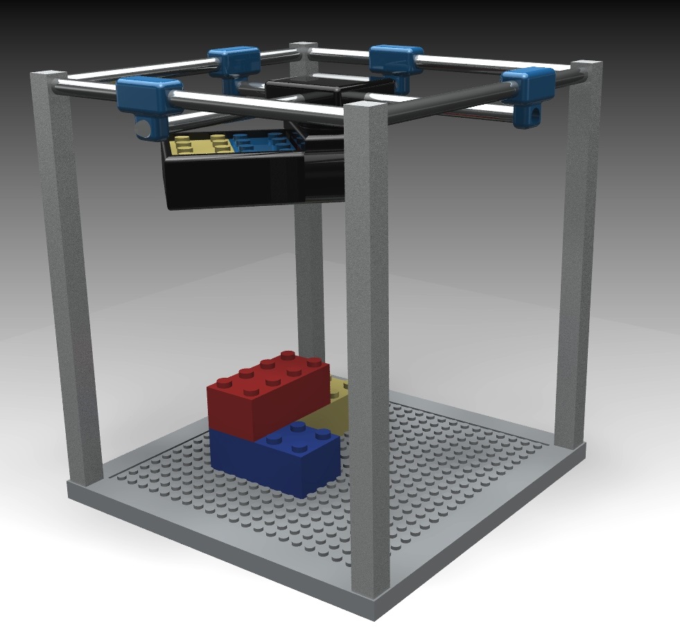
Initially, the goal was to develop a functioning, small-scale prototype. This prototype was to pick up and stack Duplo blocks basen on a given building plan as input. A 3D-model of this concept can be found in Figure 2. However, after thorough investigation, it was found that the achievability of this prototype was too low. A lot of small scale problems would have to be solved whilst there would not be enough time to discover and analyse the full-scale problems. It was therefore decided to discontinue the development and research into the prototype.
Renewed Plan: Simulation and Model
The new goal is to develop a functioning simulation with a user-friendly interface. Alongside the simulation, a detailed model will also be made. The simulation should be able to, on user input, provide the path that the printerhead should follow in order to build the desired building. This user input is yet to be determined, though, preferably, the input will be the output of a commonly used program for the designing of buildings. In this manner, the designer is not flooded with extra tasks. The interface should thereby also be self-explanatory and easy to use. The model will show a detailed concept of what the construction robot is expected to look like. The model will likely also lead to various designing issues that will be addressed in the upcoming weeks.
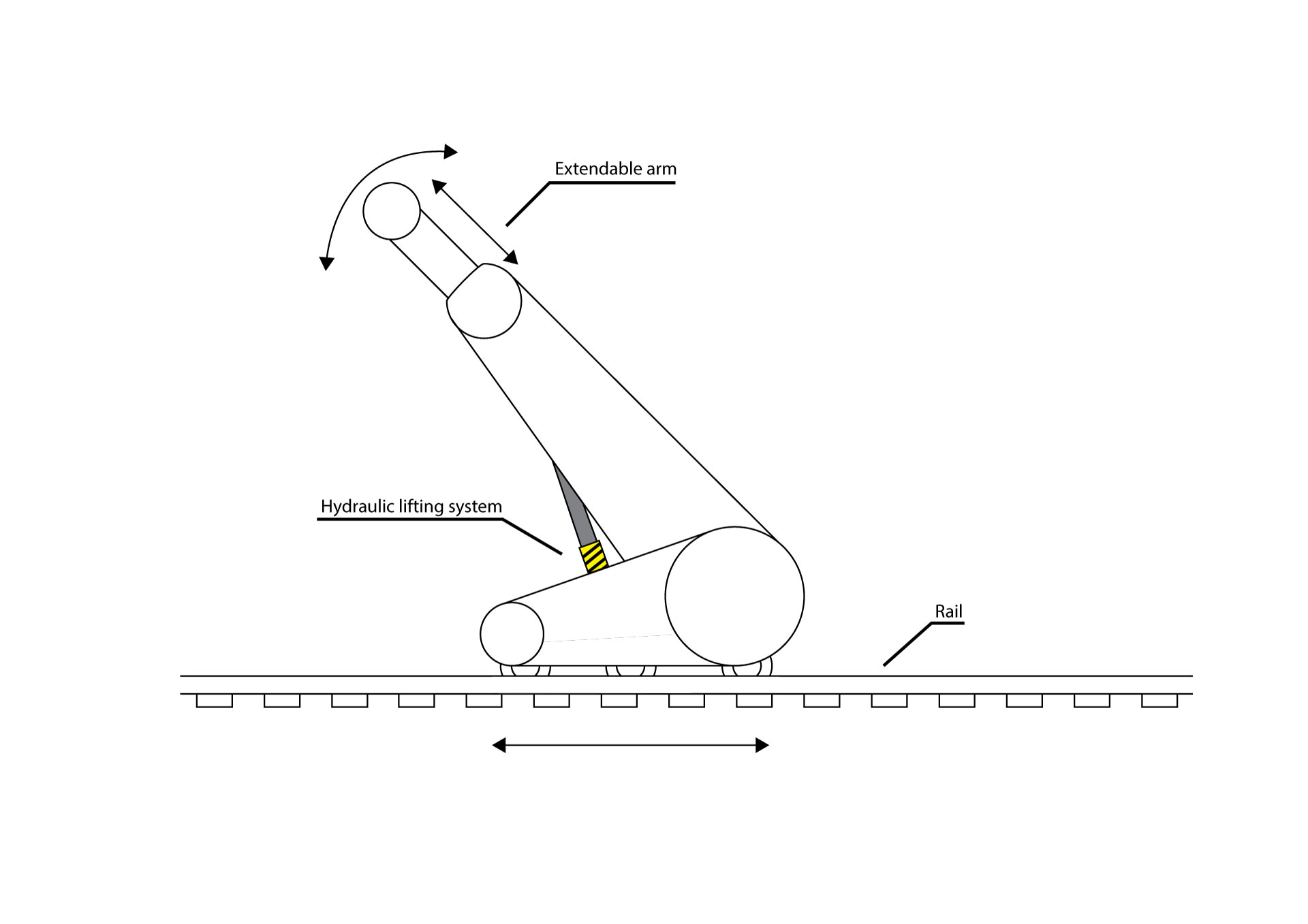
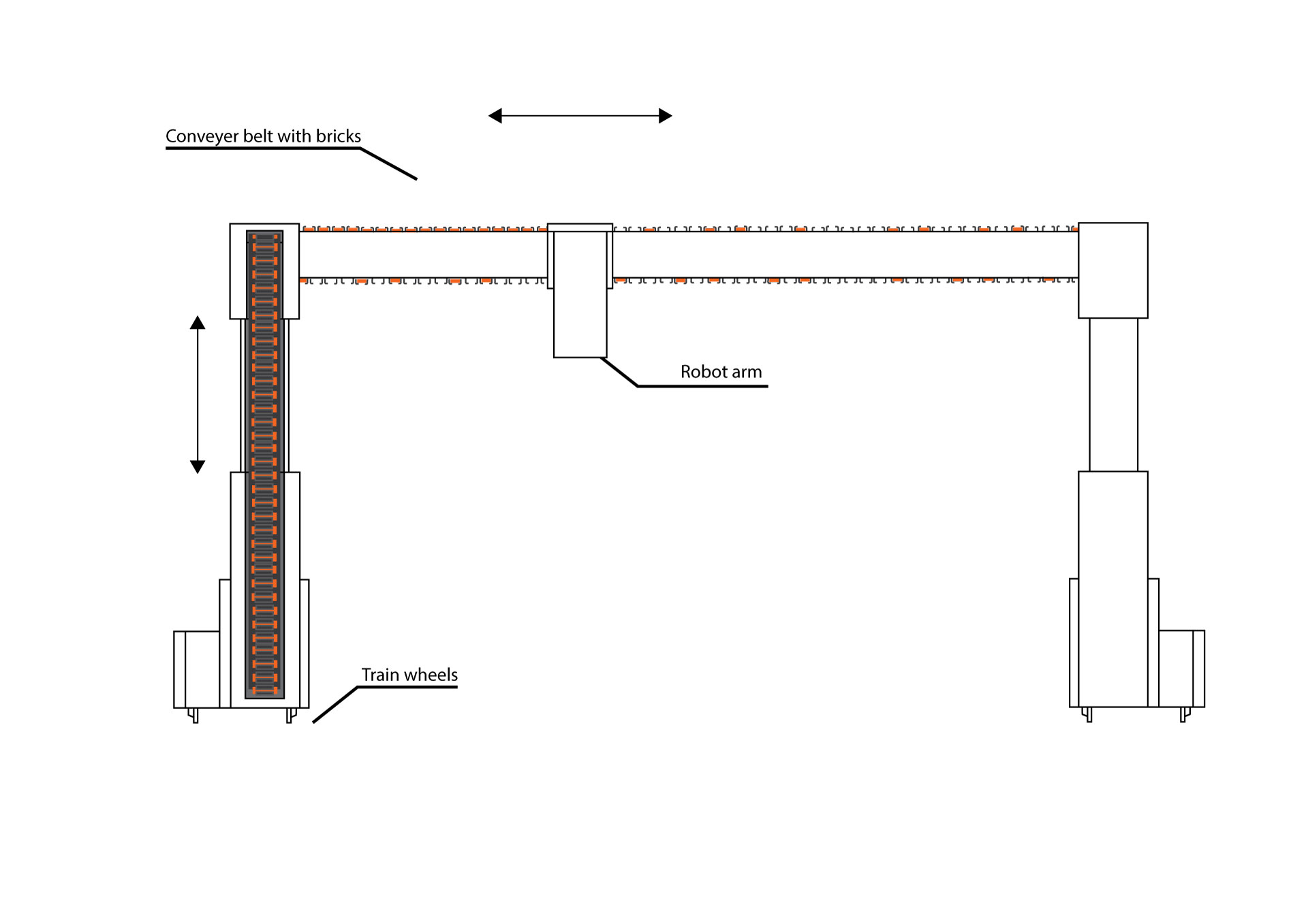
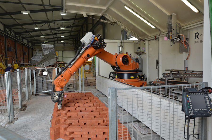
The side view of the final design can be seen in figure 1, while the front-view can be seen in figure 3. In figure 1, you can see the possible movements of the construction robot and the most special parts. The design is based on a concept of [Behrokh Khoshnevis]. The main difference between his concept is the fact that his design uses concrete to print, while the provided solution functions with bricks. In figure 3, a brick providing solution is implemented in the design. The orange blocks represent bricks, while the gray part represents a conveyor belt. Left from the robot arm the conveyor belt is filled with bricks, while at the right side, it has already used most of the bricks. The conveyor belt loops back to the beginning where it gets refilled. The whole system can be refilled with bricks by inserting brick stacks in the left side. For now, the robot arm is displayed by a rectangle. This is not representative for the concept. The robot arm should look like the one in video, and thus like a smaller version of the robot arm in figure 4.
Interview with an expert
To get a different point of view on building houses with a robot, we thought it would be a good idea to interview Theo Salet, head of the 3D concrete printing project at the structural design department. After some time and effort, an interview finally came to fruition.
At the start of the interview, the design was shown and mr. Salet was asked if he had any major remarks or changes. The first thing he noted was why we wanted to build the house on location. His goal and philosofy is to be able to print separate parts of a house one day. No more putting tubes in later, no more work in the rain. His idea to be able to design the walls with features pre-installed. Then when you want to build a house, you choose the parts you want for your dreamhouse, print all the separate parts in a factory, ship it to location and put them together in a matter of days. The different designed part have a size of a wall or sorts. His second remark was why we had a machine in mind that made something in a smaller space. Why not design multiple smaller robots, like a swarm, each with their own task, to build the house. This way there is no limit to how big you want to build and it seems more cost effective.
Then it was asked how he would solve setting windows. The answer was that the part with the window would just need a hole in the size and shape of the window. After it is printed, the window is put in and glued to the concrete. However, he did not know how electric lines should bee integrated. He hoped that the upcoming technogly of chargin by induction would be the answer to that.
The next question was how far is the technology is now. However, 3D concrete printing is still very much in the starting phase of development. The main focus of mr. Salet lab is to print constintently. At the moment people can print two of the same shapes, but sometimes the figure falls apart and someties it hardens like its supposed to. The supposed solution is to monitor al kinds of parameters like air humidity, amount of added water, temperature etcetera. and create a control loop that compares the parameters constantly to an ideal precalculated case and makes adjustments to get a working final result.
The program that would create 3D models for the printer would be based on bim. According to mr. Salet, it should calculate in the background wheter the given design is feasible with 3D concrete printing and warn you in time if that is not the case. That way, it would safe the designer a lot of time.
According to us, it seemed printing concrete would be very prone to cracks, since the material is very uniform. Mr. Salet acknowledged this and said that the idea is that ultimately the print concrete has fibers or small beads that should enhance the material to a wanted composite. For a stiffer concrete, add more deformation resistant beads, for a light concrete, keep the weight low by adding light beads. Reinforceconcrete has steel bars in it to accommodat for pull forces. The 3D concrete printer on the TU/e is the only printer that can print somewhat reinforced concrete by having a steel thread through the system that gets printed with the concrete.
Finally, we wondered how the concrete stayed soft inside the tube. The answer that the component that hardens the concrete only get added when at the print head.
When we came at the end of the interview, mr Salet welcomed us and every other student that has a cool idea, to use the 3D concrete printer for any kind of study related project. According to him, the 3D concrete printer is a studytool that is available for all students.
Simulation: Energy and Time robotarm
Robotarm
When construction robot has arrived at the desired position, a recurring set of movements will have to be done to place the bricks. This will be done by a smaller more accurate robotarm. The robotarm has to pick the bricks up, go past the cement dispenser to dispense cement on the bottom and the side and place the brick securely.
Energy
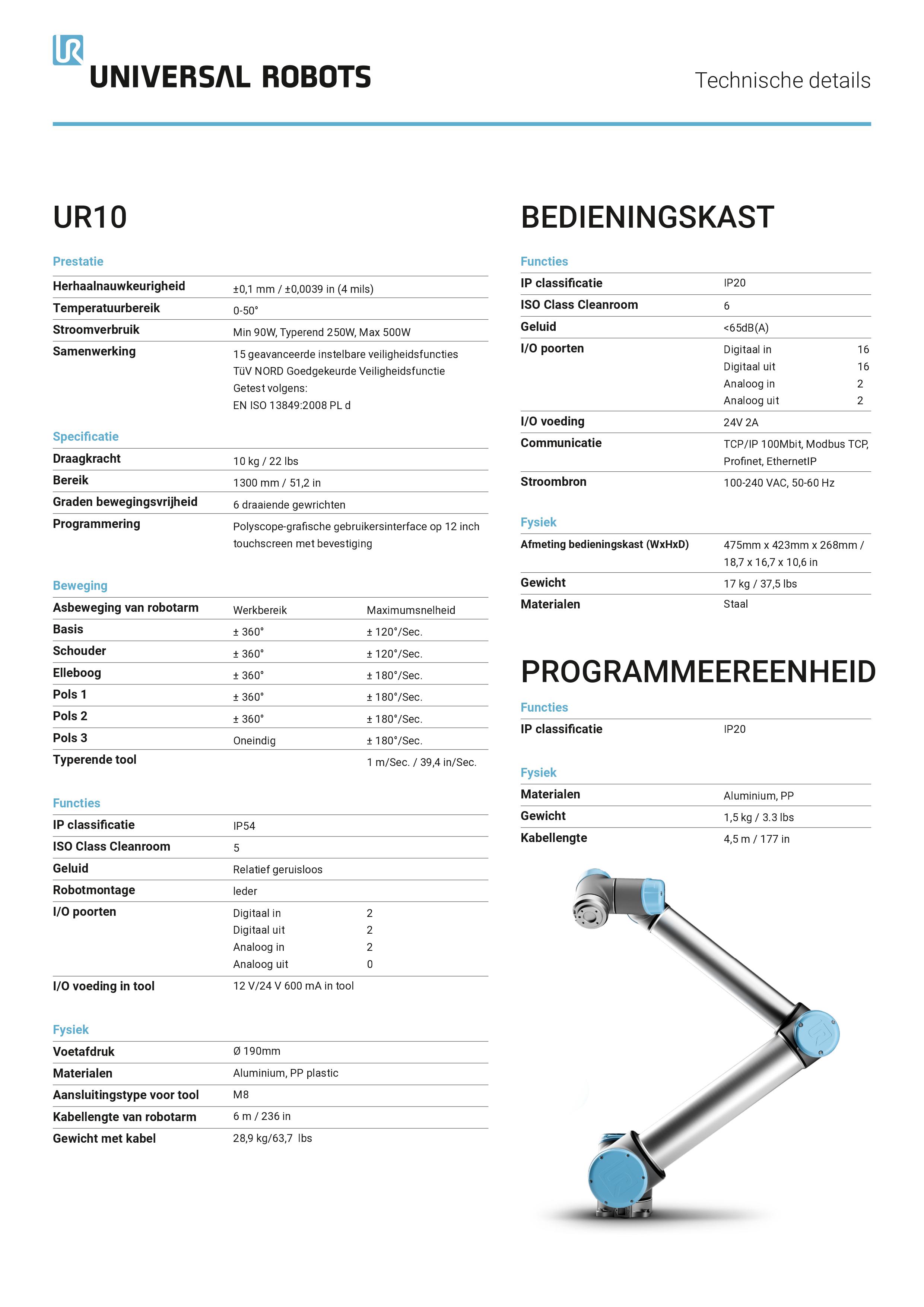
To calculate how much energy this would cost, the robot shown in Figure 5 is taken as an example. Then the moments of inertia of several parts are calculated/estimated. Followed by the estimation of the speed changes that every movement needs. Then the work is calculated of every movement and added together. Since motors are not 100 percent efficient, is the total work divided by an estimated efficiency to get the estimated energy for one placement cycle.
Time
To calculate the time, a kinematic model of the given robot has been made. This model changes the wanted x and y coordinates (of the robotarm relative to the conveyor) into the needed angles for those given coordinates. Then the difference between the angle of this situation and the last situation is calculated. The maximum speeds from the robot specs are taken and multiplied by the angle differences to calculate the time needed for that movement. Some movements however are happening simultaneously, so the movement that takes the longest time to execute only get added to the total time of the brick placing movement.
Implementation
Ultimately these scripts give a calculated energy and time respectively. These variables will be implemented in the simulation of the robot. This way the total amount of energy and time can be calculated to build the given house. This way, for each model put in, the needed efficiency and time to build the design can be presented.
Improvements and ideal concept
At the moment the movements calculated are relatively simple. It would be preferable to be able to make calculations for more complex movements, using all the differents available motors. A more complex kinematic model would be needed to transfer positions into angles.
Also there is a big estimation of the time used for the hand to grab a brick. This part of the arm could be worked out more, when the actual hand would be chosen. This way the calculations could become more accurate. The same idea holds for the arm itself. The masses of the various parts are estimated and when more information about it are present, the calculations could be improved.
There is not only one type of brick used, there are many different kinds of bricks. Bricks with different dimensions and different weigths. These parameters influence the movement and energy and calculations. What would be ideal, is that the chosen brick parameters can be put in or even chosen from a database. With these parameters, the models will then calculate the required time and energy.
Users
In the design of the robot and the software the user will play a vital role. It was therefore important to have discussion with a potential user of such a robot to see how they design. We managed to arrange an interview with Thijs Kruiselbrink PHD student of the faculty "Bouwkunde" at the TUE and asked him the following question.
What workflow do you use to design houses? Currently the Autocad software is most commonly used to design houses. Autocad is a 3D modeling software from autodesk capable of exporting 3D models in many different formats. Alternatively Bim is also starting to get more popular. Bim is very usefull since buildings are constructed virtually within the software itself, which allows its users to find problems with the design earlier.
From this we conclude that we will need a format that Bim and autodesk can export as the input for our simulation so it integrates nicely with the workflow of architects
Construction robot simulation
To simulate and visualize the construction robot, a Matlab script is written. The program works by loading a STL model into Matlab using already existing software. The program will use the vertices and faces from these model to determine where and in what order it will place it blocks. Requirements The model will be able to
- Import any 3D model exported in the STL format
- Successfully visualize the construction of a building from a model containing only rectangular shapes.
- The system should be relatively user friendly
- The system will use a proper pattern when placing the bricks to ensure stability
- The simulation will be able to deal with half bricks and tell the user how it needs certain bricks to be cut
Milestones
- Import a 3d Model
- Initialize a Grid/matrix that represents a building space.
- Determine which coordinates in the grid are (in) a wall from the faces.
- Determine which coordinates in the grid are (in) a wall for different heights.
- Define where bricks should be placed.
- Define in what order the bricks should be placed.
- Create a user-interface
BrickPath Algorithm
What should it do?
Due to a limited amount of time available for this project we will have to define what our algorithm will be able to do at the end of the project, and how it could be improved. The list of the end-of-the-project goals is the following one:
- Plot an optimal path between all bricks in the brick matrix. The algorithm will be able to come up with a path to place all stones in an efficient order, but also taking structural integrity into account.
- Give the amount of bricks as output. Because the robot plans its complete path before starting it will be able to calculate the amount of bricks and half bricks necessary for the input building. This will reduces waste of bricks and ease the work of the construction workers, who will be able to cut just as many stones as necessary.
- Give an indication for the construction time. The robot will plan its entire path before starting, as mentioned above, which will enable it to specify the time necessary for the complete construction. Of course this depends just as much on the robot itself as on its input.
- Take windows, doors and supports into account. When the design contains a door or a window (which it most certainly will) the algorithm should be able to identify them and give a signal to the construction workers that a support must be placed. The algorithm will be able to give the measurements of this support before starting the path, so the supports can be prefabricated. Lastly, the algorithm will take the time to place the support into account and continue to print somewhere else so the support can be placed.
We see more opportunities for our algorithm which cannot be implemented due to a lack of time, resources or both. These features are listed below:
- Types of masonry. For every design that will be built a list of masonry types should be selectable. The algorithm will then automatically adjust its path plan to the chosen masonry type.
- Insulation. In our current algorithm isn't taken into account. The algorithm itself will not be able to select certain insulation types on its own, this should remain a task of the architect and partially based on the wished of the future inhabitant of the house. What the algorithm should be able to have is a function that enables insulation based building, so cavity walls and insulation attachment should be taken into account.
- Electric wiring and water supply systems. An integral part of a (modern) house is the electricity and water supply. They are mostly supplied through the walls, which means our algorithm should take them into account. In the file supplied to the algorithm pipes and wires should be marked so the algorithm can consider them while building the walls. In an even more advanced system only the socket and water supply requirement locations could be input in the file and the algorithm could determine how to install the pipes and wiring itself.
- Construction workers info. Construction workers will still be important to in our robot design so the algorithm should take their wishes and needs into account. In a more advanced algorithm not only the time it will take to build the wall can be outputted, but also an entire planning that includes shifts and breaks, and the amount of construction workers necessary for a certain task such as placing a window. The workers should be able to input their preferences through an easy UI.
- Estimate necessary cement amount. Just as with the bricks, the algorithm should be able to estimate the amount of cement that is needed to complete the building based on the other input parameters. This will make construction easier and reduce waste.
- Natural disaster safety norms. In places where natural disasters such as earthquakes occur regularly the structure of buildings is adapted to them. This could also be implemented into our algorithm. Based on recommendations from structural engineers and geographists the architect or even the construction worker should be able to select a safety norm, for instance ranging from one to 5. This norm will affect how much the algorithm lets structural integrity influence the masonry type and the amount of cement necessary. It could even decided to add supporting pillars to a certain building to improve the safety of the house it is building.
Now we have described what or robot will or could be able to do it is also useful to propose what is shouldn't be able to do. Our construction robot is foremost a masonry robot, which restricts it form the ability to perform certain tasks. These tasks are listed below:
- Install wiring, water supply pipes and insulation. As mentioned above the algorithm will be able to take these factors into account, but in our intentions it should eventually not be able to plan and execute the installation of electricity wiring, water supply pipes and insulation. Implementing all of these features into one robot would make the robot overly complicated and not as effective as two (possibly smaller) robots executing the different tasks separately.
- Build roofs, doors, windows etcetera. Just as with the insulation, wiring and piping the robot will take these factors into account but will not install them. The reason is that much precision is needed to install for instance windows which would make the robot overly complicated again, while humans are still better in these tasks.
Data structure of the input
As described in SECTION, the SCRIPTCAD_NAME script takes a 3D model and gives a matrix of arrays, representing the bricks in a house with ones and zeros. The BrickPath Algorithm was written to take such a matrix and determine the optimal path for the ‘printer head’ (robot arm). The purpose of this script is to minimize the time not laying bricks. Its output, a list of coordinates sorted in an optimal order, is also used to calculate the total time and energy required for the robot to build the house. In this section, the algorithm will be described in more detail. Data structure of the input As described in the introduction, the script’s input is a matrix, stored with arrays of bricks. An example of such a house matrix is shown in Figure 6.
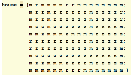
Every letter in the matrix is a cell array of length h, equal to the height of the house. The three basic arrays are: 1. m: represents a wall. A cell array containing list of h ones. 2. r: represents a wall with a window in it. The same as m, except bricks 0.4 h until and including 0.7 h are zeros: empty space in which builders place the window. 3. z: represents empty space. A cell array containing a list of h zeros.
Processing the data
In a nested for-loop, all x and y coordinates of house are put into a 2 x n list, n being the total of bricks. This list is at first unsorted so if it were fed to the robot as is, a lot of time would be wasted by moving the printer head to random bricks in the matrix.
For this reason, an optimal path has to be determined across all the bricks. It is decided to simply start with the outer walls, as these include most of the important characteristics, like windows, walls that tubes have to be installed in, etc. In order to do this, the coordinate vector is sorted four times based on the highest or lowest x or y coordinate. When the outer walls are sorted appropiately, only the inner walls remain. These do not have to be laid out in a predictable order like outer walls do. Simply letting the script spiral inwards or zig-zag across the house would result in a lot of time being spent traveling from brick to brick. A better solution has been found, which is to sort the remainder of the coordinate vector based on a minimal euclidian distance between any two points. The algorithm thus gives priority to bricks that lay in a straight line, after which it will lay remote bricks grouped in fewer numbers.
Results

In Figure 7, the algorithm is applied to the house of Figure 6. The printer head travels in the direction of the arrows, starting with the outer walls at the top left. It loops around and then moves along all the inner walls in the optimal order.
Note that the empty spaces between bricks result from the scale of the axes.
USE Aspects
Below, a short overview of USE aspects is given.
User
- The construction robot will reduce the workload of the construction workers.
- The construction robot will reduce the amount of danger construction workers are exposed to.
- The construction robot will lead to a quicker realization time of the building, which in turn leads to quicker accessibility for potential future residents.
- The construction robot will enable more possibility for personalized designs
Society
- The quicker realization time of buildings the construction robot provides, will lead to a more efficient construction sector, which in turn leads to:
- The construction sector being more able to keep up with society’s demand for more living room.
- Possibly lower house costs due to reduced construction costs. This makes owner-occupied houses more accessible to a bigger audience.
- The construction robot could be used for building aid in third world countries.
Enterprise
- The quicker realization time of buildings can save construction companies a lot of money due to being able to do more projects in less time.
- The construction robot can save construction companies money on wages for construction workers
- The construction robot can help construction companies compete better on the market.
Now, as can be seen in the list above, the concept of a construction robot can be addressed in various ways. One could choose to develop a broadly applicable robot to make it useful for everyone in the world. However, that will unnecessarily make the concept less suitable for all different classes. Therefore, one specific user is chosen to influence the design. In addition, by trying to address all USE aspects, the depth of the concept will be limited. Whilst, with this project, it is of course the goal to do in-depth research into artificial intelligence and robotics. Hence, it was decided to specify the user and main focus of this project.
As shown earlier, User, Society and Enterprise aspects are all present in the concept. However, since this system could be optimized for ‘simple’ housing and to lower costs, this project will mainly concern Society and will focus on construction in third world countries. The construction robot and simulation will be used to minimize costs, excess material and time required to build a house. By focussing on this part, other ideas will be left out of the scope of this project. Ideas such as complex structures, varying building techniques and large-scale buildings will not be considered. In this project, the construction robot and simulation will:
- Minimize excess material and thereby the reduce the material costs.
- Take limited resources into account, and will be able to deal with the use of different kinds of bricks.
- Build simple, straightforward houses that can be built easily and thereby reduce building time.
- Since slums are often on areas that are not fully level (often on hills), the construction robot will be able to operate under an angle.
Potential Users & Stakeholders
Because our USE perspective is mainly focused on Society this of course affects our stakeholders. In this part of the wiki we will describe three situations in which our construction can be used and name the different stakeholders and their interest in our project.
Slums and rapid urbanisation
Our construction robot is partially aimed at poor third/second world countries that require rapid house construction to stop the uncontrolled growth of slums. From 1990 to 2001 the global slum population grew with 220 million people, posing a huge housing problem (SOURCE). Because of this mostly governmental organisations will be interested in our project. The reasons for that are that the costs of our robot are too high for local neigbourhood communities in cities, the increased speed at which housing can be constructed and the government/municipality's responsibility for urban planning. These reasons for interest are only caused by problems such as underdeveloped city slums, but governmental organisations or building companies in third or second world countries can also be interested through the prospect of making profit from fast and cheap housing. It has to be said that our construction robot will most likely only be profitable when simple houses are built in larger numbers, which makes it more suitable for third or second world countries than western countries because the need of many cheap houses is not as big in these western countries. Another interested party could be NGO's or other organisations such as the UN promoting sustainable housing in said countries. One sustainable design with for example room for solar panels and a shared electricity grid can be implemented into the robot which can be built over and over again. This makes it very suitable for such sustainable housing projects because with more houses comes a more reliable local electricity grid. Of course the NGO's could coöperate with the local governmental organisations mentioned at the start of this paragraph. Of course there is one other group of stakeholders, which is the people that will live in the houses constructed by our machine. These people that previously lived in the slums or outside the city don't have very high demands of their housing (the quality of slum and rural housing in third/second world countries isn't particularly high). Because of this relatively small and cheap houses with basic facilities such as electricity and water will suffice. The houses should also be cheap because the people living there will have to be able to maintain their house in a good state and also be able to purchase a house (possibly with governmental subsidies).
Refugee camps
Another situation where fast and rapid housing comes in handy is a refugee camp. Refugee camps now mostly exist of tents, which aren't a very good solution for long term housing. Our construction robot would be able to rapidly build appropriate housing to replace tents. It will still be large organisations such as local governments in countries with many refugees (such as Greece and Libanon) or for instance Unicef that use our robot because the costs are too high for small charity organisations or the refugees themselves. The same advantages as slum-replacement (easily scaleable, more reliable electricity grid) still apply, but using our machine for refugee camps has one big disadvantage. This disadvantage is recyclability. Because most refugeecamps are temporarily camps the house could be abandoned once the refugees are able to return to their homes. Tents have the advantage over our houses in this case because they can be taken apart easily and moved elsewhere. This implies the houses built for refugee camps should be easily recyclable, which would practically make them advanced tents. However, charity organisations and governments providing shelter to refugees could still be interested in our robot because some refugeecamps are open for as long as ten years (Dadaab camps in Kenya, Breidjing camp in Chad) which require more robust housing. The refugees that will live in the houses built by our robot are also a group of stakeholder. Just as with the slum population, their demands aren't very high and their housing quality will most likely increase because they currently live in tents or don't have shelter at all. Basic facilities such as electricity and water should be provided, but where the slum population could partially pay for these facilities this is mostly not the case with refugees. This means the housing and the including facilities should all be paid for by other stakeholder such as governments and charity organisations, implying that the housing will be as cheap as possible.
Settlements
As made clear in the two previous parts of this paragraph, the main advantage of our construction robot is the possibility of rapid house construction. This offers great opportunities when facing rapid urbanisation and large groups of refugees, but can also be misused. An example of this is the Israeli colonization of Palestine. Since the 1967 Six-Day War Israel has been building settlements in Syrian, Egyptian but predominantly Palestine territory, although being pressured by the UN and the western world not to do so since it is illegal. Israel hasn't yielded to this pressure but only expanded its illegal settlements. Our construction robot could be used to rapidly build these settlements which would cause even more aggressive Israeli expansion politics. In this case, the Israeli government would be the main stakeholder, since it will be the main user of our machine and instruct or promote its building companies to use it to build the settlements. In this case, the houses should be bigger and its facilities more extensive because the Israeli people that will live there are used to a higher housing standard. This won't be a problem since our construction robot will be able to handle various house designs. In the same way militaries could use our construction robot to build military bases in disputed areas, or could even help completing Trump's infamous wall in a shorter timespan and with less costs.
Construction workers
Finally, a group of stakeholders not mentioned in the examples above but applicable to them all are the construction workers. With our robot the workflow on a construction site will drastically change. Construction workers will still be necessary to place windows, roofs, doors etcetera but the masonry will be done by our robot. The masonry is an integral part of every building which means the construction workers will have to "coöperate" with the robot, meaning that the robot will give a signal when for instance windows can be placed or when it has run out of bricks. The robot can also accidently break down, so the construction workers should have a basic understanding of the way the robot works to fix it. This all requires a training on working with the construction robot. Our robot could also lead to possible unemployment for construction workers. When the robot only builds the walls of a house this may only affect masons, but it could be developed further and load to unemployment for all groups of construction workers.
General planning


The general planning is displayed in a GANT chart, which can be seen in figure 6. Because of the major change in the deliverable, a new planning had to be made. The old planning is visible in figure 5. In the GANT-chart activities, the work distribution and milestones can be seen. The planning will be adjusted if necessary.
week 1
- Deciding on the subject of the project
- Preparing the presentation about the concept.
week 2
- Concept Presentation
- Preparing the second presentation about the planning.
- Start working on wiki, explaining the concept and the deliverables
week 3
- Planning Presentation
- Rework project based on feedback
- Arrange meeting with TU/e Concrete Printing
- Start creating a list of required components for the deliverable
- Start working on the enterprise plan: Potential Users
- Update wiki
week 4
- Milestone: Order components for the deliverable
- Start desiging and printing components for the deliverable
- Finish Potential Users
- Start working on the enterprise plan: Social impact
- Update wiki
week 5
- Work out new deliverable
- Start working on the enterprise plan: Estimated costs
- Finish Social impact
- Update wiki
week 6
- Finish Estimated costs
- Start working on the enterprise plan: Business proposal
- Milestone: Illustrations of final design
- Update wiki
week 7
- Finish Enterprise plan
- Milestone: Business proposal
- Milestone: Simulation, Model and User interface
- Update wiki
week 8
- Buffer week
- Prepare final presentation
- Update wiki
Action plan
The initial step in the assembly of the robot is to get the green light for its creation. To ensure that the scope of the project is indeed properly defined. Once the theoretical background is sufficiently explored the construction of the robot can start. The construction can be divided in a few segments.
- Acquiring the required components
- Physical assembly
- Calibration
- Software implementation
- General Debugging
Action plan renewed
Originally the plan was to build a prototype, however that is no longer the case. We are going to emphasize on a simulation. This means that we don't have to wait on parts or a budget, but can work on our computers by ourselves. The plan right now is to develop a script that can make a 3D map in a matlab enviroment from a stl file taken from NX. Besides that a script has to developed that determines and executes the best path of for the robot to place the bricks. While in this script the actual position of the smaller robot arm is not simulated, the energy and time it takes to execute its actions have to be taken into account and calculated. These parameters have to be implemented in the placement script, so the placement script can give energy and time costs as output. When these objectives are met and are working, other aspects can be elaborated into. These aspects can for example be different brick laying styles or more complicated building shapes instead of lines with right angles
- Translating NX to Matlab environment
- Develop path making algorithm
- Calculate and implement energy and time costs
- Testing and refining
- General Debugging
- Elaboration into new aspects
External sources
http://www.tue.nl/3DConcretePrinting
[1] http://www.home-building-answers.com/house-foundations.html
[3] https://theconstructor.org/earthquake/earthquake-resistant-techniques/5607/