Viotar/Hardware Design: Difference between revisions
No edit summary |
|||
| Line 93: | Line 93: | ||
<math>M_{w}</math> is calculated by <math>M_{w}=R\cdot F_{w}=R\cdot F_{n}\cdot \mu_{w}</math>, with <math>F_{n}=F_{b}</math> the normal force between the bowing belt and the string. This equivalent bow force has a maximum of <math>4 N</math>. The value of <math>\mu_{w}</math> is estimated at a rather high <math>0.7</math>. The radius <math>R</math> of the wheel over which the belt runs is taken to be <math>10 mm</math>, in practice it will be smaller than this. | <math>M_{w}</math> is calculated by <math>M_{w}=R\cdot F_{w}=R\cdot F_{n}\cdot \mu_{w}</math>, with <math>F_{n}=F_{b}</math> the normal force between the bowing belt and the string. This equivalent bow force has a maximum of <math>4 N</math>. The value of <math>\mu_{w}</math> is estimated at a rather high <math>0.7</math>. The radius <math>R</math> of the wheel over which the belt runs is taken to be <math>10 mm</math>, in practice it will be smaller than this. | ||
<math>M_{br}</math> is calculated assuming cylindrical roller bearings will be used. For cylindrical roller bearings <math>M_{br}</math> equals <math>F\mu_{w}d/2</math>, with <math>mu_{w}=0.002</math> the friction coëfficient for cylindrical roller bearings, <math>F</math> the force on the bearing, and <math>d</math> the shaft diameter, which is about <math>4 mm</math> for a bearing with a outer diameter of <math>11 mm</math>. | <math>M_{br}</math> is calculated assuming cylindrical roller bearings will be used. For cylindrical roller bearings <math>M_{br}</math> equals <math>F\mu_{w}d/2</math>, with <math>mu_{w}=0.002</math> the friction coëfficient for cylindrical roller bearings, <math>F</math> the force on the bearing which is estimated at <math>30 N</math>, and <math>d</math> the shaft diameter, which is about <math>4 mm</math> for a bearing with a outer diameter of <math>11 mm</math>. | ||
Revision as of 15:37, 22 November 2010
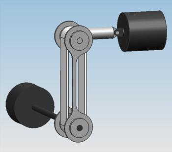
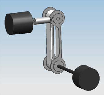
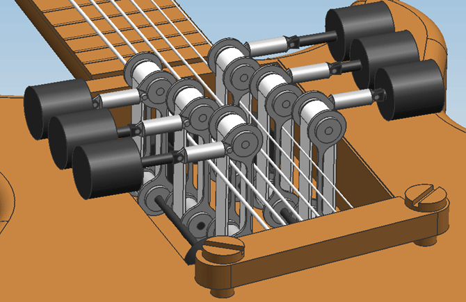
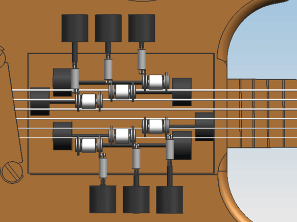
Design 0.1On friday the 5th of november, the first attempt at a design was finished. Only geometric constraints were taken into account, meaning the size of the engines and actuators were solely adjusted to the amount of space that was available in the guitar.
Design 0.2From reviewing design 0.1 with the group, the following points of improvement were determined:
These improvements have been worked into design 0.2. Estimation of the required motor powerMath test: [math]\displaystyle{ 0 }[/math] [math]\displaystyle{ P=M_{T} }[/math] The needed motor power is calculated using [math]\displaystyle{ P=M_{T}*\Omega }[/math]. For this, the total load [math]\displaystyle{ M_{T} }[/math] and the angular speed [math]\displaystyle{ \Omega }[/math] should be calculated. The total motor load consists of the load coming from the friction of the bowing belt with the string [math]\displaystyle{ M_{w} }[/math] and the friction of the bearing supporting the wheel that drives the belt, [math]\displaystyle{ M_{br} }[/math].
[math]\displaystyle{ M_{br} }[/math] is calculated assuming cylindrical roller bearings will be used. For cylindrical roller bearings [math]\displaystyle{ M_{br} }[/math] equals [math]\displaystyle{ F\mu_{w}d/2 }[/math], with [math]\displaystyle{ mu_{w}=0.002 }[/math] the friction coëfficient for cylindrical roller bearings, [math]\displaystyle{ F }[/math] the force on the bearing which is estimated at [math]\displaystyle{ 30 N }[/math], and [math]\displaystyle{ d }[/math] the shaft diameter, which is about [math]\displaystyle{ 4 mm }[/math] for a bearing with a outer diameter of [math]\displaystyle{ 11 mm }[/math].
|


