Viotar/Hardware Design: Difference between revisions
| Line 20: | Line 20: | ||
|- | |- | ||
|} | |} | ||
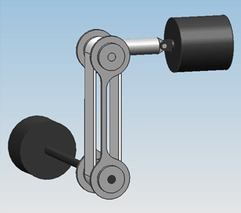
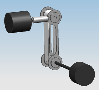
The bowing mechanic for a single string in Design 0.1. A motor at the bottom (black) drives the bowing belt (white), which is pushed against the string by an actuator at the top (black), with a spring shaft in between. | The bowing mechanic for a single string in Design 0.1. A motor at the bottom (black) drives the bowing belt (white), which is pushed against the string by an actuator at the top (black), with a spring shaft in between. | ||
|- | |- | ||
Revision as of 13:57, 11 November 2010
Introduction
The design progress of the hardware, meaning the actual instrument, is described here.
Design 0.1
On friday the 5th of november, the first attempt at a design was finished. Only geometric constraints were taken into account, meaning the size of the engines and actuators were solely adjusted to the amount of space that was available in the guitar.
|
The bowing mechanic for a single string in Design 0.1. A motor at the bottom (black) drives the bowing belt (white), which is pushed against the string by an actuator at the top (black), with a spring shaft in between. |
Design 0.2
From reviewing design 0.1 with the group, the following points of improvement were determined:
- There is too little space for the engines, so their spacial configuration should be altered so that they can be bigger.
- There shouldn't be motors on the neck side of the construction, because that forces the construction towards the bridge, leaving less space for the player to pluck the strings.
- An estimation should be done on the size of the motors, based upon an estimation of the power that is required from them.
These improvements have been worked into design 0.2.
Estimation of the required motor power
The needed motor power is calculated using [math]\displaystyle{ P=M_{T}*\Omega }[/math]. For this, the total load [math]\displaystyle{ M_{T} }[/math] and the angular speed [math]\displaystyle{ \Omega }[/math] should be calculated.
The total motor load consists of the load coming from the friction of the bowing belt with the string [math]\displaystyle{ F_{w} }[/math] and the friction of the bearing supporting the wheel that drives the belt, [math]\displaystyle{ F_{b} }[/math].
[math]\displaystyle{ F_w=F_n*μ_w }[/math]
F_n is waarschijnlijk ongeveer gelijk aan 20 [N], μ_w zal dan wel ergens rond de 0.7 zitten. Hierdoor word de formule:
F_w=4*0.8=3.2 N
Nu weten de wrijvingskracht ongeveer. Verder is er nog wrijving in de lagers/wielen die meegenomen moet worden. Als we er nu van uit gaan dat er roller bearings genomen worden met cilindrische lagers, dan geldt voor de wrijving:
M_r=F*f*d/2
Met:
M_r=wrijvingskoppel
F=kracht op het lager
f=wrijvingscoefficient,voor cilindrical rollerbearings 0.002
d=diameter van de schacht (ongeveer 4 mm voor een lager met 11mm diameter
Geeft als schatting van de ordegrote:
M_r=30*0.002*4/2=0.12Nmm
Aangezien de lagers een straal hebben van nooit meer dan 10mm word de wrijvingskracht in de lagers nooit hoger dan 1 [N]. Voor 2 lagers komt de absoluut maximale kracht dan op 2 [N]. De totale kracht die de motor dan moet kunnen leveren is dan ongeveer gelijk aan 16[N], dit is dan wel de kracht bij stationair toerental.
Rotatie-energie lager:
E=1/2 J_z (φ^2 ) ̇,J_z=1/2 mr^2 geeft samen:E=1/4 mr^2 (φ^2 ) ̇=1/4*0.0017*〖0.01〗^2*300*2*π=8*〖10〗^(-5)
Dat is dus niet heel veel (een lager weegt 0.0017 kg volgens skf).
M_w=3.2*10=32Nmm,M_tot=32+0.12=32Nmm
P=M_T∙Ω=0.032*300=10 W
[math]\displaystyle{
\operatorname{erfc}(x) =
\frac{2}{\sqrt{\pi}} \int_x^{\infty} e^{-t^2}\,dt =
\frac{e^{-x^2}}{x\sqrt{\pi}}\sum_{n=0}^\infty (-1)^n \frac{(2n)!}{n!(2x)^{2n}}
}[/math]

