Embedded Motion Control 2015 Group 3: Difference between revisions
No edit summary |
|||
| Line 227: | Line 227: | ||
= Videos = | = Videos = | ||
Experiment 3: Testing the potential field on May 29, 2015. | |||
* https://youtu.be/UAZqDMAHKq8 | |||
Revision as of 13:00, 29 May 2015
This is the Wiki-page for EMC-group 3.
Group members
| Name | Student number | |
|---|---|---|
| Max van Lith | 0767328 | m.m.g.v.lith@student.tue.nl |
| Shengling Shi | 0925030 | s.shi@student.tue.nl |
| Michèl Lammers | 0824359 | m.r.lammers@student.tue.nl |
| Jasper Verhoeven | 0780966 | j.w.h.verhoeven@student.tue.nl |
| Ricardo Shousha | 0772504 | r.shousha@student.tue.nl |
| Sjors Kamps | 0793442 | j.w.m.kamps@student.tue.nl |
| Stephan van Nispen | 0764290 | s.h.m.v.nispen@student.tue.nl |
| Luuk Zwaans | 0743596 | l.w.a.zwaans@student.tue.nl |
| Sander Hermanussen | 0774293 | s.j.hermanussen@student.tue.nl |
| Bart van Dongen | 0777752 | b.c.h.v.dongen@student.tue.nl |
Log
Project
This course is about software design and how to apply this in the context of autonomous robots. The accompanying assignment is about applying this knowledge to a real-life robotics task.
The goal of this course is to acquire knowledge and insight about the design and implementation of embedded motion systems. Furthermore, the purpose is to develop insight in the possibilities and limitations in relation with the embedded environment (actuators, sensors, processors, RTOS). To make this operational and to practically implement an embedded control system for an autonomous robot in the Maze Challenge, in which the robot has to find its way out in a maze.
PICO is the name of the robot that will be used. Basically, PICO has two types of inputs:
- The laser data from the laser range finder
- The odometry data from the wheels
In the fourth week there is the "Corridor Compitition". During this challenge, called the corridor competition the students have to let the robot drive through a corridor and then take the first exit.
At the end of the project, the "A-maze-ing challenge" has to be solved. The goal of this competition is to let PICO autonomously drive through a maze and find the exit.
Week 1
Here, we present a summary of our initial design ideas:
Requirements
Two requirements are devised, based on the description of the maze challenge. The first one is to be able to complete the challenge by finding a way out of the maze. The second requirement is that the robot should avoid bumping into the walls or doors. While this second requirement is not necessary for the completion of the challenge, it is helpful for the longevity and operation of the robot.
Functions
The robot will know a number of basic functions. These functions can be divided into two categories: actions and skills. The actions are the most basic actions the robot will be able to do. The skills are specific sets of actions that accomplish a certain goal. The list of actions is as follows:
- Drive
- Turn
- Scan
- Wait
These actions are used for the skills. The list of skills is as follows:
- Drive to location
- Drive to a position in the maze based on the information in the map. This includes (multiple) drive and turn actions. Driving will also always include scanning to ensure there are no collisions.
- Check for doors
- Wait at the potential door location for a predetermined time period while scanning the distance to the potential door to check if it opens.
- Locate obstacles
- Measure the preset minimum safe distance from the walls or measure not moving as expected according to the driving action.
- Map the environment
- Store the relative positions of all discovered object and doors and incorporate them into a map.
These skills are then used in the higher order behaviors of the software. These are specified in the specifications section.
Specifications
The first specification results from the second requirement: Driving without bumping into objects. In order to do this, the robot uses its sensors to scan the surroundings. It then adjusts its speed and direction to maintain a safe distance from the walls.
The way the robot will solve the maze comprises of a few principle things the robot will be able to do. Because of the addition of doors in the maze, the strategy of wall hugging is no longer effective. Hence a different approach is required. The second specification is that the robot will remember what it has seen of the maze and that it makes a map accordingly. The robot should then use this map to decide which avenue it should explore. The escape strategy of the robot is an algorithm. Because the doors in the maze might not be clearly distinguishable, they might be difficult to detect. The only way to know for sure if a door is present at a certain location, is to stand still in front of the door until it opens. Standing still in front of every piece of wall in order to check for the presence of doors takes a long time and is therefore not desirable for escaping the maze as fast as possible. Therefore the robot first assumes that there are no doors in the way to the exit. It then explores by following the wall and taking every left turn. Whenever a dead end is hit, the robot goes back to the last intersection and chooses the next left path. Because the robot maps the maze, it knows whether it has explored an area and when it moves in a loop.
If no exit is found under the assumption that there are no doors, the robot starts checking for doors. See Figure 1 for different possible situations of where the doors are located. At first it assumes that there can only be doors at dead ends (1). If still no solution is found the robot also checks for doors at corners (2), followed by intersections (3) and finally on every outside wall of the currently mapped maze. In order to detect these doors the robot stands in front of the potential door for a certain time and checks with its sensors whether the distance to the nearest wall changes.

Uncertainties
Certain aspects of the design are not yet clear due to uncertainties in the specifications of the robot and/ or the maze challenge. Depending on the difference between the end of the maze and the inside of the maze, the robot may be enabled to detect it has completed the challenge. If however the outside of the maze is simply an open space similar to a place inside the maze, the robot might not be able to distinguish the difference. In this case the robot would have to be stopped manually.
The exact specifications of the robot are still unknown and without testing the precise accuracy and range of the sensors, the resolution of the map and the safe wall distance are unknown.
In order to make the robot complete the challenge faster control over the speed of the robot could be used. This way it could move faster in area’s it has already mapped. This is only possible if the robot has the capability of moving at different speeds.
Week 2
Week 2 consisted mainly of trying to get all the tutorials to work. Only at the end of the week, we could actually get started on our project. We had a little brainstorm session to gather ideas to include in our software:
• Detecting openings in a corridor
• Detecting walls while driving straight
• Taking a corner
• Detecting walls while driving around a corner
• Drive in the middle of a corridor •Stopping for obstacles • What action do we need to take when an obstacle has been recognized? • What to do when it hits an obstacle that has not been detected by the sensors? [ed • Mapping the driven route (not necessary for corridor challenge)
• Recognizing dead ends, subsequently turning around.
• Indicate that the robot has found a door and wants to pass (beeping, sounding a horn, make a 360, use the pan-tilt function of the head, firing a missile...)(not necessary for corridor challenge)
Week 3 and later...
Four main blocks
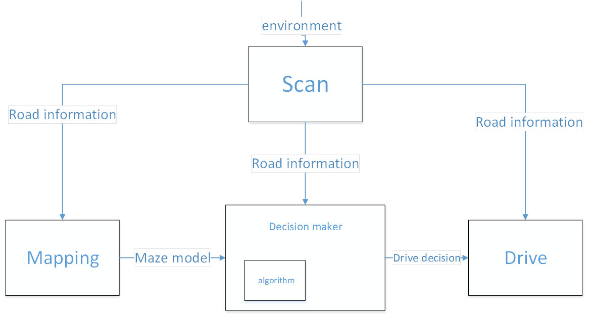
The problem is divided in different blocks. We have chosen to make these four blocks; Drive, Scan, Decision and Mapping. The next figure is a schematic representation of the connection between these blocks:

Drive block
The drive part can, for the corridor challenge, do two things: go straight in a corridor, and take a corner (left or right).
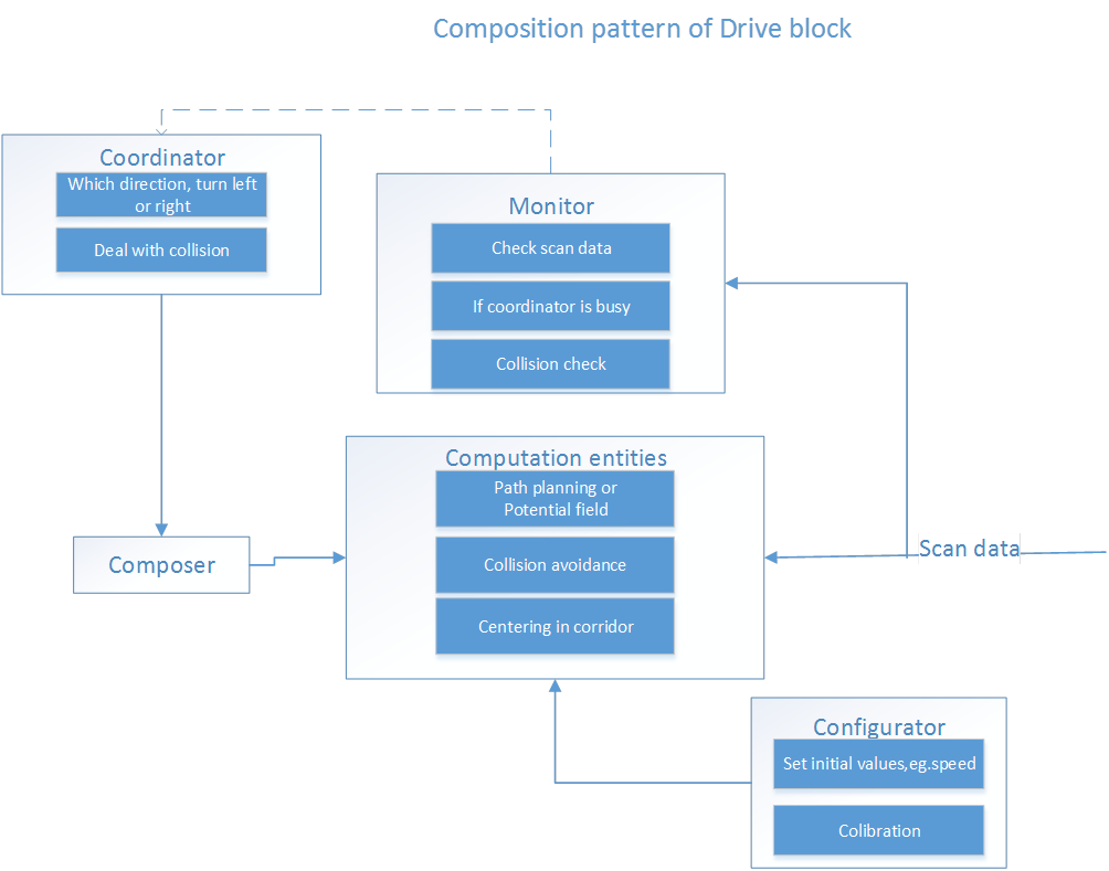
Going straight in a corridor is done by checking the closest points at the left-hand and right-hand side of the corridor, since this will be where the wall is perpendicular to the robot. Based on that, it checks what the correct angle for driving should be (difference between left and right angle). Then, it calculates the deviation from the centerline of the corridor, and based on a desired forward speed, it calculates a movement vector. Finally, it translates this vector to the local robot driving coordinates. It should be noted that the Drive class is not responsible for deciding whether it's driving in a corridor, so this particular algorithm is not robust for corners, intersections etc.
Taking a corner is done by looking at the two corner points of the side exit. Then, it tries to orient the robot to bisect the angle between those corner points, while maintaining forward speed. This way, a corner will be taken. The main vulnerability here is taking the corner too narrow, so a distance from the wall will be kept.
The composition pattern of the drive block:

Scan block
Decision block
- Mapping model
- Scan data
- Specific drive action command
Different situations when visiting a node
- If it is a dead-end node
- Did the door open for me
- Any unvisited paths
- Any paths with 1 visit
- Paths with 2 visit (not a choice)
Mapping block
Three people were assigned to the wayfinding/maze-solving/mapping task. They decided to work alone for one week to see what kind of solutions they would come up with. In the meeting of 20 May, the entire group will decide on the solution that seems to be best.
A decision was made to use the Tremaux algorithm: [1].

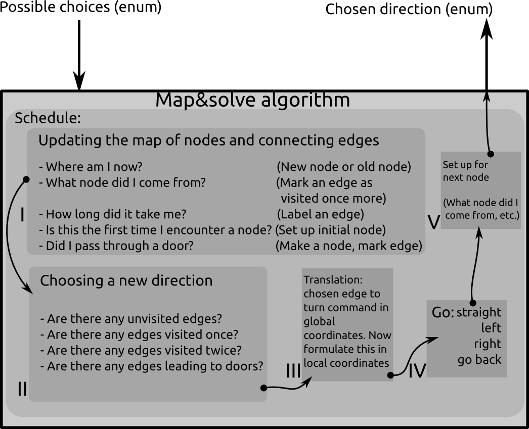
The maze will consist of nodes and edges. A node is either a dead end, or any place in the maze where the robot can go in more than one direction. an edge is the connection between one node and another. An edge may also lead to the same node. In the latter case, this edge is a loop. The algorithm is called by the general decision maker whenever the robot encounters a node (junction or a dead end). The input of the algorithm is the possible routes the robot can go (left, straight ahead, right, turn around) and the output is a choice of possible directions that will lead to solving the maze.
The schedule looks like this:
- Updating the map:
- Robot tries to find where he is located in global coordinates. Now it can decide if it is on a new node or on an old node.
- The robot figures out from which node it came from. Now it can define what edge it has been traversing. It marks the edge as 'visited once more'.
- All sorts of other properties may be associated with the edge. Energy consumption, traveling time, shape of the edge... This is not necessary for the algorithm, but it may help formulating more advanced weighting functions for optimizations.
- The robot will also have to realize if the current node is connected to a dead end. In that case, it will request the possible door to open.
- Choosing a new direction:
- Check if the door opened for me. In that case: Go straight ahead and mark the edge that lead up to the door as Visited 2 times. If not, choose the edge where you came from
- Are there any unvisited edges connected to the current node? In that case, follow the edge straight in front of you if that one is unvisited. Otherwise, follow the unvisited edge that is on your left. Otherwise, follow the unvisited edge on your right.
- Are there any edges visited once? Do not go there if there are any unvisited edges. If there are only edges that are visited once, follow the one straight ahead. Otherwise left, otherwise right.
- Are there any edges visited twice? Do not go there. According to the Tremaux algorithm, there must be an edge left to explore (visited once or not yet), or you are back at the starting point and the maze has no solution.
- Translation from chosen edge to turn command:
- The nodes are stored in a global coordinate system. The edges have a vector pointing from the node to the direction of the edge in global coordinates. The robot must receive a command that will guide it through the maze in local coordinates.
- The actual command is formulated
- A set-up is made for the next node
- e.g., the current node is saved as a 'nodeWhereICameFrom', so the next time the algorithm is called, it knows where it came from and start figuring out the next step.
Three methods
During this project, we have worked on three different methods. Basically, the approaches are getting better to the end. The 'Drive' and 'Scan' block have to be adapt for each method. The 'Decision' and 'Mapping' are independent of these methods.
Simple method
The first approach is the most simple one, that is why it is called the simple method. This also means that is not the most fancy one. However, it is still important to have this working because we can always use this method when the other methods fail. In addition, we have learned a lot from it and used is as base for the other methods.
In brief, the simple method contains 3 steps:
- Drive to corridor without collision.
- Detect opening (left of right) and stop in front of it.
- Turn 90 degrees and start driving again.
This method is a robust way to pass the corridor challenge. Although, it would not be the fastest way.
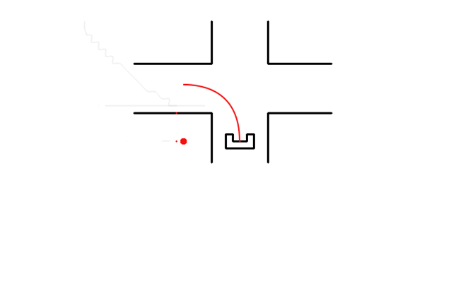
Pathplanning for turning

Potential field
Presentations
- First presentation (week 3): File:Group3 May6.pdf
- Second presentation (week 6): File:Group3 May27.pdf
Videos
Experiment 3: Testing the potential field on May 29, 2015.