Mobile Robot Control 2021 Group 4: Difference between revisions
TUe\20168550 (talk | contribs) |
TUe\20168550 (talk | contribs) |
||
| Line 65: | Line 65: | ||
* In every of these states the robot will check if the finish line is reached. This is done by counting the amount of infinite values in the laser range data, once the counter surpasses a set value the end of the corridor is reached and thus the finish line is passed. | * In every of these states the robot will check if the finish line is reached. This is done by counting the amount of infinite values in the laser range data, once the counter surpasses a set value the end of the corridor is reached and thus the finish line is passed. | ||
[[File:beun_escape_room_corridor.png|400px|thumb|center|Figure 3: Range checking inside the corridor.]] | |||
Revision as of 15:29, 13 May 2021
Group Members
Luuk Verstegen - 1252488
Bob Bindels - 1246348
Stijn van den Broek - 1252011
Lars van Dooren - 1249169
Tjeerd Ickenroth - 1232296
Introduction
Design Document
A Design Document is created in order to elaborate the approach of the Escape Room challenge (also some Hospital challenge aspects). The document includes several topics such as the requirement, components, specifications, functions and interfaces. Download the file here: Design Document
Escape Room Challenge
The task of the escape room challenge is to find the corridor and exit the room through it. Since our group did not have much experience with C++ programming, it was decided to split up the work into a robust method (2 people) and a less robust method (3 people):
- Robust: the first method is based on line segments and corner detection. From the LRF data the angle indices corresponding to start- and endpoints of line segments can be found. From these indices and the corresponding distances the location of the corridor entrance can be determined. The robot should drive to this position and from there on align itself with the walls of the corridor and drive parallel to the walls until the finish is reached. Since not a lot from the Wiki example can be used here, it was expected that this method would take the most time to get it properly working.
- Less robust: the second method is based on the full example which has been placed on the Wiki. Here, wall detection, drive control and a finite state machine are already implemented and therefore it is relatively easy to adapt. The method for finding the corridor in this method is a relatively easy one: when a sudden distance jump is found between one LRF index and the next, then the corridor is found. To make sure that once the robot has found this sudden distance jump and drives towards the corridor, mostly changes in the finite state machine are required.
Robust method
For the first method, line segmenting is implemented. This is done as follows:
1. First, a line is drawn between the start point with index 0 and the end point with index 999.
2. Then, for each LRF data point, the distance perpendicular to the line drawn in step 1 is determined and both index and distance of the point corresponding to the largest distance are saved.
3. If the distance lies above a certain threshold value, then the point found in step 2 does not lie on the line drawn between points 0 and 999. In that case, the process is repeated from step 1 again, however now the end point is changed to the index determined in step 2. If the distance lies below the threshold value, then there is a line detected between the start and end point stated in step 1. The process is then repeated with the end point of the current iteration now being the start point of the next iteration.
4. The steps above are repeated until the start point index is equal to 999, which means that all line segments have been found.
Note that since all the start and end points of the line segments are saved, also the corner indices are known. A problem which had to be dealt with using this method is the fact that when the robot is driving in the open-ended corridor, certain distances in the LRF data are close to zero since the laser beams sent outside the corridor are not reflected by a wall or object. This resulted in the robot detecting the indices corresponding to angles pointed outside the corridor as corners, which obviously is not the case. Therefore, at each instance the robot receives new LRF data, the indices which correspond to a distance smaller than 0.1 m are stored and later taken out of the array of corner indices. The result is that only the indices of the actual corners remain.
Another problem, which was not solved at the time of the challenge, is the fact that not between all subsequent corner indices a line should be drawn. For example, when the robot is driving straight through the corridor it detects the ends of the left and right wall as corners, however in between these corners there is no wall. This distinction should be made such that the robot knows where a wall is located and where not, such that he can align to the walls in the corridor. At the time of the challenge it was not yet figured out how this should be done.
For the detection of the corridor two methods where thought of:
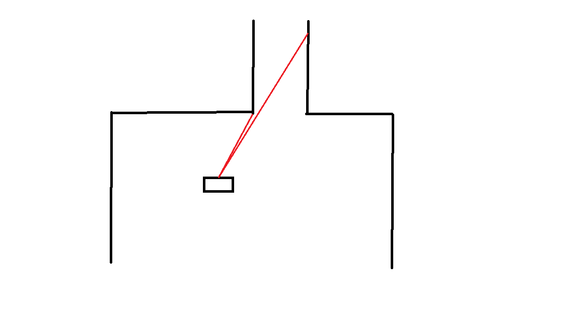
- The first method for detecting the corridor is based on a jump in distance between subsequent corner indices which are within a certain index bound w.r.t. each other, this is visualized in Figure 1. When this jump is detected, the robot should rotate and drive towards the corner with the smallest distance and from there on perform a similar kind of movement as explained in the less robust method. When detecting the corridor in this way the main difference between the robust and less robust method is that the robust method only checks for a distance jump between the corner indices instead of all indices, thus saving computation time. A disadvantage of this method is that the robot cannot detect the corridor when it is right in front of the corridor, since then the index gap between the left and right corner is out of the specified bound.
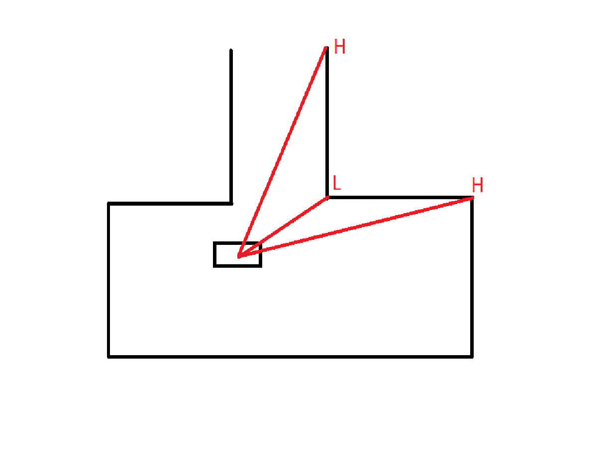
- The second method for detecting the corridor is based on convexity of the corner points. When a high-low-high sequence in distance is found between three successive corner points, then the middle corner is one of the corners at the entrance of the corridor. This is visualized in Figure 2. Unfortunately due to time constraints it was not possible to successfully implement this before the escape room challenge.


Less robust method
This algorithm works as follows. At first the robot will search for large differences between two subsequent points from the LRF. The program continuously look trough the data and if the range of two consecutive data points have a larger difference than 0.5 meter the program will assume that the corridor is found. This is illustrated in Figure 1. If initially no corridor is found the robot will rotate such that it has seen the entire view of 360 degrees. It could be the case that still no corridor is found because the room is too big. Then the robot will just drive forward and stop just before hitting a wall. It will then drive a bit backwards and search again for the corridor, this process will repeat until the corridor is found.
When the corridor is found the robot will rotate until the corridor is in front of it. The robot will now drive towards the detected corner point of the corridor. When the robot has reached the corner, it will drive a bit sideways until it has enough space to move forward. Now the assumption can be made with great certainty that the robot is located in the corridor. To drive out of the corridor the following steps are be taken by the algorithm:
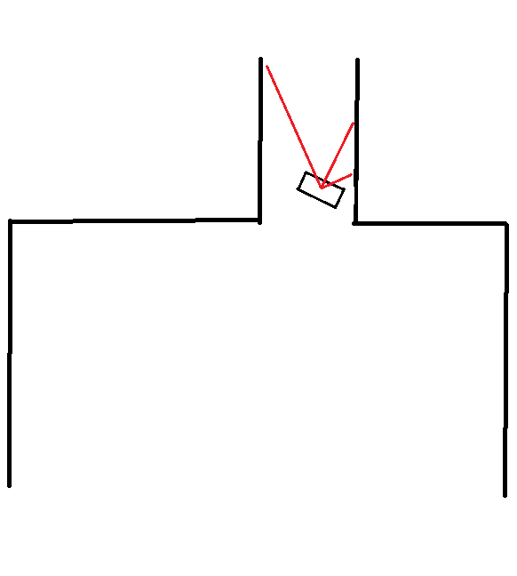
- If the robot almost hits a wall it will check which of the ranges depicted in Figure 3 is the furthest.
- The robot will now drive in the positive x-direction, positive y-direction, or negative y-direction depending on which of the ranges in step 1 is the furthest.
- This process keeps repeating, which results the robot to be driving out of the corridor in a zigzag like pattern.
- In every of these states the robot will check if the finish line is reached. This is done by counting the amount of infinite values in the laser range data, once the counter surpasses a set value the end of the corridor is reached and thus the finish line is passed.
