AutoRef implementation: Difference between revisions
20204919@TUE (talk | contribs) |
20204919@TUE (talk | contribs) |
||
| Line 61: | Line 61: | ||
- The system development starts from the fourth week, which means that the team needs to complete the system development in five weeks, and the mature and ready-made V-model process can save a lot of time spent on project management. | - The system development starts from the fourth week, which means that the team needs to complete the system development in five weeks, and the mature and ready-made V-model process can save a lot of time spent on project management. | ||
<center>[[File:v-model.png]]</center> | |||
Based on the general V-model, a detailed test plan has been made for the verification of the system both from functional and performance perspectives. | Based on the general V-model, a detailed test plan has been made for the verification of the system both from functional and performance perspectives. | ||
Revision as of 15:35, 31 March 2021
The implementation for the AutoRef autonomous referee for RoboCup Middle Size League (MSL) robot soccer is the proposed design of the AutoRef system.
In 2021 contributions by MSD 2020 focused on detecting ball-to-player distance violations.
Introduction
Objective statement
The main objective of the implementation part of the project was to detect violations of the rules related to the distance between the ball and players during the following game states:
- Free kick
- Kick-off
- Corner kick
- Goal kick
- Throw-in
- Dropped-ball
- Penalty kick
These rules are described in Laws number 8, 10, 13, 14, and 15 of the MSL Rulebook.
Motivation
This objective was chosen due to several reasons:
- Past projects analysis has shown that this functionality has never been designed before
- Stakeholder interviews (the MSL referees) have led to the conclusion that this kind of rules are hard to control for a human being
- Proof of concept for the developed functional specification was desirable
- Learning goals of the team members correspond to the technical solutions necessary for the functionality development
Scope of work
The following topics were included in the implementation scope:
- Requirements formulation
- Architectural decomposition development
- Individual code blocks development
- Individual code integration
- Software testing on images and videos
These topics are explained in detail in the following sections.
Process model
Introduction
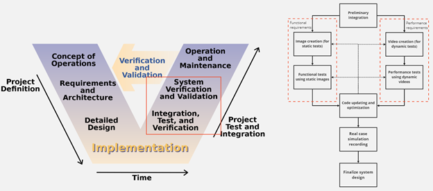
The development activities of the design team need support from process models. In this project, the V-model is chosen to guide the development procedure from requirement engineering to system validation. Due to the particularity of the project itself, some details of the model have been changed. At the same time, the agile approach was used during system development and combined with the traditional V-model, which makes the project progress more flexible and efficient.
Use of V-model
V-model has the following advantages for the development of the project:
- Design team's project is based on machine vision and software algorithms. V-model was first proposed in the software development environment and has matured in the software development field.
- The project team has five members, all of whom can participate in the development of subsystems and they can be developed at the same time. On the premise that the system architecture is determined, V-model can greatly improve the development efficiency.
- The system development starts from the fourth week, which means that the team needs to complete the system development in five weeks, and the mature and ready-made V-model process can save a lot of time spent on project management.

Based on the general V-model, a detailed test plan has been made for the verification of the system both from functional and performance perspectives.
Based on the requirements derivation results, functional and performance requirements were set up and related tests were planned as shown in the figure above. In this plan, the details of the V-model are supplemented, and more detailed test steps and iterations are added in the test and verification phases. The technical blocks were integrated into the first phase, then several images regarding typical use cases are created from the simulation environment (refer to Section 3) in order to verify the functional requirements. Videos were created to test the performance of the system based on particular scenarios (refer to Section 4). Code was updated iteratively after several times of tests. After the code was verified, a simulated game video was created in the simulation environment to illustrate how the system works in the 'real' world.