RoboShark: Difference between revisions
No edit summary |
|||
| Line 1: | Line 1: | ||
Project by Twan Haazen <br> | Project by Twan Haazen <br> | ||
Supervisor Rob Janssen | Supervisor Rob Janssen | ||
This wiki will contain information about my Bachelor Final Project. | This wiki will contain information about my Bachelor Final Project. | ||
Revision as of 15:04, 16 July 2011
Project by Twan Haazen
Supervisor Rob Janssen
This wiki will contain information about my Bachelor Final Project.
Introduction
Lorem ipsum dolor sit amet, consectetur adipiscing elit. Sed vestibulum convallis justo, at vulputate risus vulputate et. Fusce non velit vitae quam dapibus ullamcorper. Lorem ipsum dolor sit amet, consectetur adipiscing elit. Integer tincidunt rhoncus massa, ac fermentum risus sollicitudin vitae. Nulla vitae orci sit amet erat feugiat malesuada a a leo. Vestibulum sem ligula, aliquet eu blandit eget, gravida vel eros. Maecenas pharetra congue massa at sodales. Aenean condimentum, tellus id sagittis malesuada, nibh nunc feugiat orci, dictum consectetur lacus neque sit amet sapien. Class aptent taciti sociosqu ad litora torquent per conubia nostra, per inceptos himenaeos. Morbi adipiscing arcu ullamcorper purus commodo ac elementum augue hendrerit. Pellentesque volutpat enim sed tortor consequat in iaculis ante pharetra. Cras tristique semper urna, id bibendum sapien lobortis id. Donec nisi eros, mattis sed fermentum sit amet, accumsan a libero. Sed sapien mauris, varius a placerat eget, ultricies at ligula. Mauris dignissim ornare pulvinar. Nulla facilisi. Cras nec interdum est. Integer quis accumsan sapien. Quisque vehicula, metus id accumsan fringilla, mauris mauris adipiscing nisi, eget molestie velit mi et lorem. Maecenas augue massa, pulvinar sed adipiscing at, posuere eget dolor. Nam ligula odio, ultricies sit amet mollis sit amet, gravida at erat. Donec pellentesque, nisl at rutrum posuere, nibh urna tincidunt turpis, imperdiet gravida massa nisl nec nunc. Ut in felis ut quam posuere mattis. Nam quis tortor quis arcu scelerisque tincidunt. Vivamus non euismod purus.
Pre-Design Research
In this section two things are discussed. First the most important parts of brainstorm sessions are pointed out. Some basic design problems are stated and taken into account. The second part is about helium. Because the balloon of the shark will be filled with helium, it is important to know what amount of weight the helium can actually lift. The mathematical derivation is discussed and the relation between weight and amount of helium needed is stated.
Brainstorm Sessions
After the decision was made to base the design on a shark, the actual brainstorm sessions began. The most important parts of the these brainstorm session will be discussed here.
The first thing that came to mind, was to search for as much information as possible about projects that did about the same as I was planning to do. When discussing the assignment, the german company Festo had some interesting video's and projects about helium filled balloons. Festo developed the Air Penguin as well as the Air Ray. The Air Penguin is an autonomously flying penguin that communicates with other penguins in the air. The Air Penguin makes sure it does not hit any walls or obstacles and does this by using ultrasound to pinpoint its location. The Air Ray is a remote controlled helium filled balloon which simulates the flying mechanism of a manta ray. Both these projects are closely related to the product I would like to produce. By exploring the website of Festo and contacting the people that worked on these projects, I tried to get as much information as possible to get a clear vision on how to design my shark.
One of the first things that can be concluded from of both of these projects is that the construction has to be very light. The Air Penguin, with a length of 4 meters and a maximum diameter of 80 centimeters, had a total weight of only 1 kg. This requires well use of construction material and space.
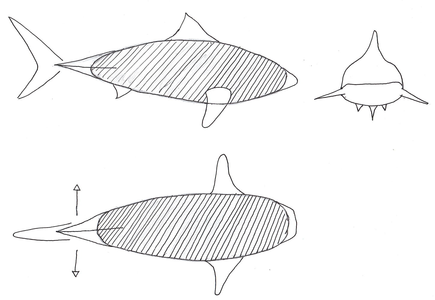
After studying the designs of Festo, the first sketch of the prototype is drawn. The first idea consisted of a large balloon filled with helium, produced in the shape of a shark's body. Onto this large sack the several components of the shark are attached. The tail section is made out of several thin rods which will be moved in horizontal direction by a servo. This part will function as the propulsion of the shark. With the side fins the shark can turn and move up and down. The fins can be rotated and the tips can be moved op and down to make steering possible. Their functionality is about the same as the wings of a bird, but then without the flapping. Next to that the top fin can also be used to enhance the steering procedure. The fin can be rotated around it's vertical axle and therefore produce more drag at a certain angle, resulting the shark to move into a certain direction. The first sketch is shown in figure (X).
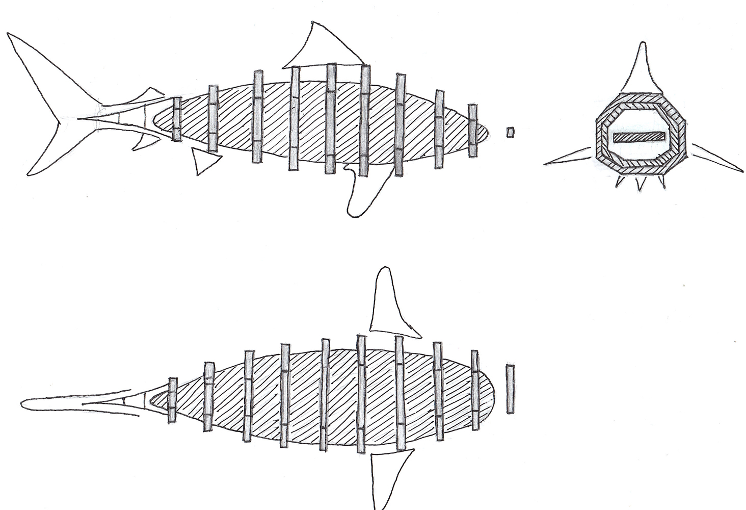
The second sketch the design has changed. To make the structure more rigid and define the shape better a frame is added. The tail section will also consist of a frame section instead of only 4 single rods as in the previous design. The propulsion is still the same, with the tail section move in horizontal direction using a servo. The steering in this second section can be done in two ways, but the method to do it with still has to be chosen. One option is using the same steering mechanism as used in the first sketch, so by using the side fins. The second method is deforming the balloon using the frame. Thin wire are run through holes in the frame section from beginning to end. By pulling on these wire, the body will deform and the nose will bend in the direction it wants to move. Due to the airflow alongside of the shark, a resulting force will push the shark it's body in the right direction. The second sketch is shown in figure (X). There is a problem with this sketch, the weight of the total frame construction might be to heavy for the helium filled balloon to keep the shark neutrally buoyant.
Using the ideas of the brainstorms sessions, the several parts of the shark can now be designed using both paper as well as a 3D CAD-design. But first needs to be determined how much weights helium can lift.
Helium
The shark will float through the air by using helium. To determine how much helium is needed to make the shark neutrally buoyant Archimedes’ principle is used. This principle states that any object, wholly or partially immersed in a fluid, is buoyed up by a force equal to the weight of the fluid displaced by the object. In the following section a relationship between the mass of the shark and the volume of the balloon needed is derived. Following Archimedes' principle, the upward lift is defined in equation (1).
The whole shark will have a certain weight on which a gravitational force is applied. The total amount of gravitational force is given in equation (2).
To make the shark neutrally buoyant the force from the upward lift has to be equal to the force applied by gravity, which is displayed in equation (3). If the upward lift equals the gravitational force, no net force in vertical direction will be present.
Substituting the terms from equation (1) and (2) in to equation (3), a relation between the mass of the shark and the amount of helium needed can be derived. This relation is given in equation (5).
[math]\displaystyle{ \rho_{air} \cdot g \cdot V = (M_{shark} + \rho_{helium} \cdot V) \cdot g \qquad (4) }[/math]
[math]\displaystyle{ M_{shark} = (\rho_{air} - \rho_{helium} ) \cdot V \qquad (5) }[/math]
In equation (6) M is the molar mass, P is the pressure, R is the universal gas constant, and T is the absolute temperature. If the assumption is made that the temperature is equal to 293K and the pressure is 1 bar, the density of air is, according to equation (6), equal to 1,204 kg per cubic meter. At the same conditions the density of helium is 0,1787 kg per cubic meter. Using these values for the densities of air and helium, 1 cubic meter of helium can make 1 kg neutrally buoyant. Using equation (5), the size of the balloon needed to make the shark neutrally buoyant can be determined.
Design
In this section the different design stages will be discussed. First the tale section is explained. The working mechanism and sketches are shown. After the tail section, the main body part is pointed out. Different kinds of design are discussed and the the sketches and visualizations are shown.
Tale Section Design
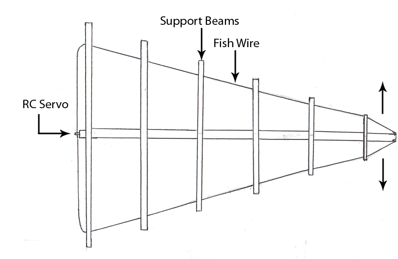
The first part of the shark that is designed, is the tail section of the shark. This part will function as the propulsion of the fish. In figure (X) the sketch of the rear section is shown. At the right side of the sketch the tail fin will be attached, and the left part of the sketch will be attached to the body of the shark. By studying the swimming of a shark, the part that actually moves of the shark's tale is the part between the tail fin and the body section. This part makes a horizontal translation by moving sideways. To model this into my prototype, a flexible rod in the center will be used as the backbone of the tail section. On this flexible rod several support beams are mounted to define the shape of the tail section and to guide the fish rod that is used. The fish rod is used to obtain the needed deformation of the center flexible rod. The fish rod is connected to the tip of the center flexible rod and is run through the support beams to the RC servo that is mounted at the start of the flexible rod. If pulled on one end of the fish rod, the flexible rod will deform in such a way that it will bend in the direction of the side where the force is applied. If the force is applied first on one side and, after the desired deformation is acquired, on the other side and this is repeated every time. The rod will bend first to one side and afterwards to the other side. This results in the desired horizontal translation that is needed for the proper propulsion of the shark.
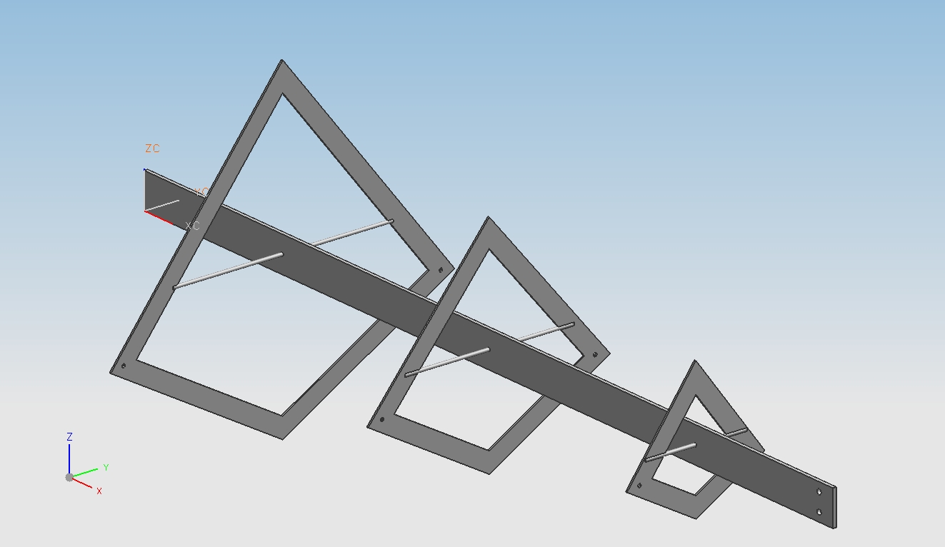
Next to a sketch of this idea, a 3D CAD-design has also been made. This design is show in figure (X). In this design only three rods are used, this will give enough shape definition throughout the length of the tail section. Using only three section will also make sure the design stays light weighted. Adding more support beams will add a lot of mass to the shark. The 3D CAD-design will be used to make the prototype of this section.
Body Section Design
The body section has been changed a lot during the period of designing. Several ideas were tested and compared on weight and feasibility with respect to the actual prototype building. Each different designs will be discussed, one more briefly than the other, according to the time spend on the design.
Steering Using Fins
The first design consisted of a large shark-shaped balloon as body section. Through this body runs a tube that connects both side fins. Using a servo the tube can be rotated and so are the fins. By rotating the fins, the shark can move up and down. The fins will function like airplane wings, if one side is turned upwards and thus the other side is going down, a lift force on the top or bottom will be generated moving the the shark either up or down. So by changing the angle of attack of the side fin, different kinds of lift can be generated. The second feature of the fins is the movement of the tip. A servo is build in to make the tip of the fin move up or down. If one tip of the shark is moved up and the tip of the other fin is pointing down, the shark should be able to turn left or right. But this method needs to be tested.
This design might not be the most efficient design there is. The first downside of this design is the complexity of the fins. To make sure the fins can move in each direction, at least three servos are needed. This adds a lot of weight to the shark. Next to that, creating a tube that runs through a gas tight and helium filled balloon is hard. But one of the most important downsides is that this design does not represent the real movement of a shark. When different videos of sharks are analyzed, it's clear that a shark moves up and down, left and right by turn its torso in the direction it wants to go. The side fins function only as stabilizers and improve the aerodynamics of the shark.
A new design needs to be created that uses the deformation of the torso to make steering of the shark possible.
Steering Using Frame
The previous design was not the desired design that is needed to make a realistic representation of the shark. Therefore a different approach is used. Not the side fins are used to make steering possible, but the whole torso section will used.
The main part of the body section is the balloon. The balloon will be a large sack which is based on cone shapes to make production more efficient. Around this balloon several frame parts are added to provide the distinctive shape of the shark. Through these parts four thin fish rods will run to make deformation possible. One rod will run over the top of the shark, one over the bottom and one on each side of the shark. The deformation principle is similar to the one used with the tale section. By make the rod shorter on one side and longer on the opposite side, the balloon deforms. If for instance the fish rod on the right side is made shorter and thus the one on the left side is made longer, the tip of the shark will move to the right. Due to this deformation of the sharks body section, the airflow around it will change also. In this case, the pressure on the left side of the shark will be higher than the pressure on the right side of the shark. A net force resulting from this pressure difference will push the shark in the direction the tip is pointing to. Once the desired turn is achieved, the rods are brought back to their original length and the shark will move in a straight horizontal line again. By letting the shark change direction using the deformation of the body, the realistic representation is achieved. Following up on this theoretical idea, an 3D CAD-model is made.
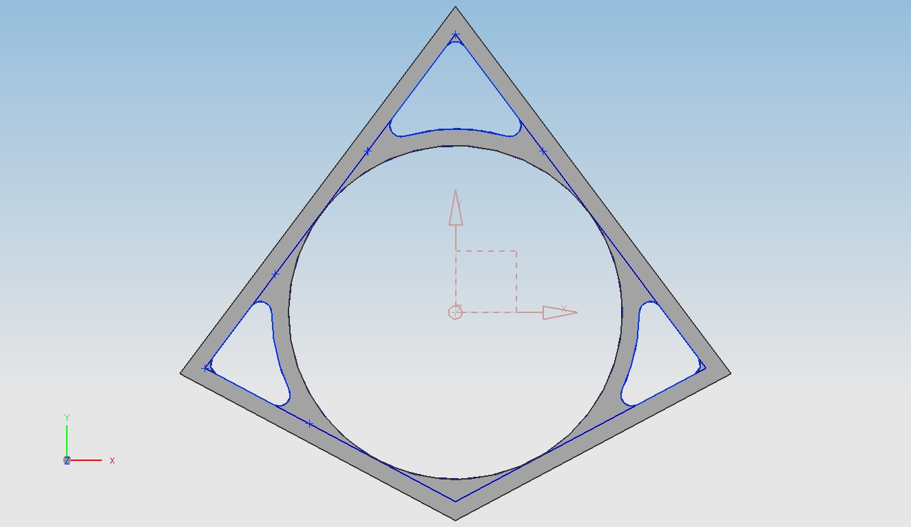
My first design of the frame part, shown in figure (X), didn't seen like the optimal design. A lot of material is still present at the side, which would define the shape of the body. Because there is so much material needed to make the frame design, the weight of the total structure is to high. Using the design as in figure (X), the weight of the biggest frame section, the one in the middle of the body with a inner radius of 300mm, is 195 grams. In this case I use carbon fiber as the material for the frame, with a density of 1600 grams per cubic meter. The thickness of the frame part of only 1 mm. With the weight of 195 grams, 0,195 cubic meters of helium is needed to make this frame part neutrally buoyant. The corresponds with a length of a balloon, with a radius of 300mm, of almost 70cm. And this is just to make this part neutrally buoyant,
if it also has to make batteries, servos and other things neutrally buoyant, a lot of length needs to be added. And thus the length of the balloon needs to be increased.
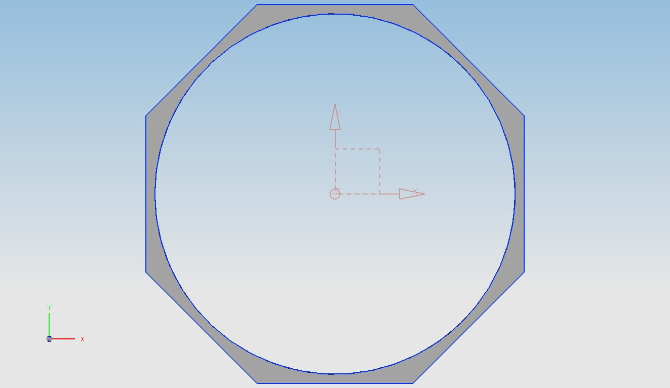
Another option is to redesign the frame section. When taking a closer look at the body of a shark, it does not have four sides. It can be better modeled using eight sides. A plus of this design is that the borders can be thinner and therefore the weight is decreased. With the new design, shown in figure (X), the weight is about 75 grams. This also involves using carbon fiber, a inner radius of 300mm and a thickness of 1mm. The length of the balloon needed to make the frame part neutrally buoyant is now 27cm. This design saves a lot of weight compared to the first design, while still preserving the shape of the shark. Now all of the different frame parts can be designed, as well as the balloon that will contain the helium. With these parts a model of the whole shark can be made.
The model of the body section can be seen in figure (X). In figure (X) the tail section is added for completion of the whole shark. Using this model several things can be calculated. One of the things is the volume of all the several frame parts, as well as the volume of the balloons.
Separate Balloons
Frame And Separate Balloons
Prototypes
Tail Section Prototype
After the designing phase, a prototype has been build. The flexible rod is a part of flexible plastic and the in between parts are made out of MDF. Small holes have been drilled into these parts to allow the fish wire to run through it. When applying force into these wires the tale of the shark bends as required. This is shown in the figures below.