Embedded Motion Control 2014 Group 9: Difference between revisions
| Line 131: | Line 131: | ||
[[File:Scan straight.png|thumb|center|500px]] For the detection of the world and the desired direction, two scripts have been implemented. These two are visualised in the figure. | [[File:Scan straight.png|thumb|center|500px]] For the detection of the world and the desired direction, two scripts have been implemented. These two are visualised in the figure. | ||
Scanxy; (purple lines) | |||
== Scanxy; (purple lines) == | |||
This function reviews the laserdata and tranlates them to a structure with their x and y distance with respect to pico. | This function reviews the laserdata and tranlates them to a structure with their x and y distance with respect to pico. | ||
Straightdetect; (other lines) | == | ||
Straightdetect; (other lines) == | |||
This function uses the result of scanxy, a struct of x and y coordinates. It analyzes the direction of the corridor with respect to the orientation of pico. It does this by looking at 2 laser points and comparing the dx and dy to calculate an angle. For robustness this process is repeated for multiple pairs of dots, the results are filtered and averaged. This results in a good and robust measurement of the angle which pico could rotate to be located straight in the corridor. | This function uses the result of scanxy, a struct of x and y coordinates. It analyzes the direction of the corridor with respect to the orientation of pico. It does this by looking at 2 laser points and comparing the dx and dy to calculate an angle. For robustness this process is repeated for multiple pairs of dots, the results are filtered and averaged. This results in a good and robust measurement of the angle which pico could rotate to be located straight in the corridor. | ||
Revision as of 11:26, 26 May 2014
Team members
| Name | Student # | Remark | |
| Koos Elferink | k.elferink@student.tue.nl | 0716494 | |
| Joost Potma | j.potma@student.tue.nl | 0864146 | |
| Jasper Spanjaards | j.j.a.spanjaards@student.tue.nl | 0746039 | |
| Jordi van Dijk | j.v.dijk@student.tue.nl | 0805981 | |
| René Bruintjes | r.f.bruintjes@student.tue.nl | 0877139 |
Planning
Week 1
- Installing Ubuntu
- Installing ROS
- Installing SVN
- Follow tutorial C++
Week 2
- Install Qt-creator (IDE)
- Group meeting to make a start on the project
- Test robot with standard script
- Test robot with added self made script parts
Week 3
- Group meeting (goal: finish corridor script)
- Second test on robot (test script)
- Corridor contest (16 May)
Week 4
- Group meeting (goal: maze solving strategy)
- Function to make Pico drive straight through the maze. (Koos)
- Make proper software architecture with nodes/topics (Joost/René)
- Start writing arrow detection algorithm (Jordi/Jasper)
- Measure laser distances during pico test
Future
- 20 June: Maze contest
progress week 2
-progress and format was discussed. Tasks were divided. For the corridor competition we need a set of four functions, all with input the laser data,(first increment starts at the left), output and type given, extra output possible for future extensions (as separate function)
Corridor detection: CL, CR (type bool) true if a corridor is at ~90deg left/right of pico. Laserpoints on left and right are scanned and when value becomes large, this implies corridor. -> Jordi
Driving: Vx, Vy, Vz (etc) -> straight, safe, and aligned driving. Also steering towards corners/endstops -> Koos
Result: library implemented, have not been able to test yet. 2 function created for area reconnaissance. One for translating laser data into coordinates, another to relate that data to straight driving objective of pico
Corner: Vx, Vy, Vz (etc), override -> action when CL or CR is true, overrides driving function -> Rene
end: Vx, Vy, Vz (etc), exit -> for stopping after finish -> Jasper
Combining in main() -> Joost
progress week 3
The code written for the corridor competition was written and tested. Even though the code functioned very well in the simulator, it did not function on the real pico. Corridors on the left were taken without problems but right corners were ignored. Pico detected the right corridors well, and also took the decision to turn right. However the right turn command was not executed properly. After reordering the code, the right turns were taken fine.
Simple parallel wall driving

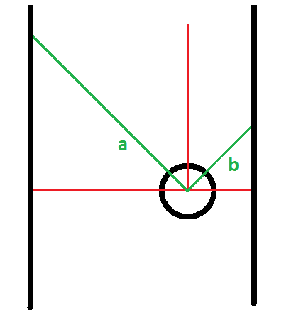
A simple way is implemented to drive parallel next to the wall.
The distance to the wall is measured in at an angle of 45deg left (a) and right (b). If the distance become below a threshold than pico will rotate in opposite direction as long as there is the wall (or other obstacle) within it's range.
Simple corner (corridor) detect

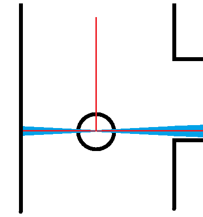
A simple corner (corridor) detect is impmlemented in a seperate function. On the left and right side side corridors are detected by scanning an angle of -95 -> -85 and 85 -> 95 of pico. If 95% or more laserdata points within a range is higher than a treashold, than a corridor is detected. A detected corridor, left and/or right, is send a boolean the the navigation script as a return value.
Script overview for corridor contest
to be done
progress week 4
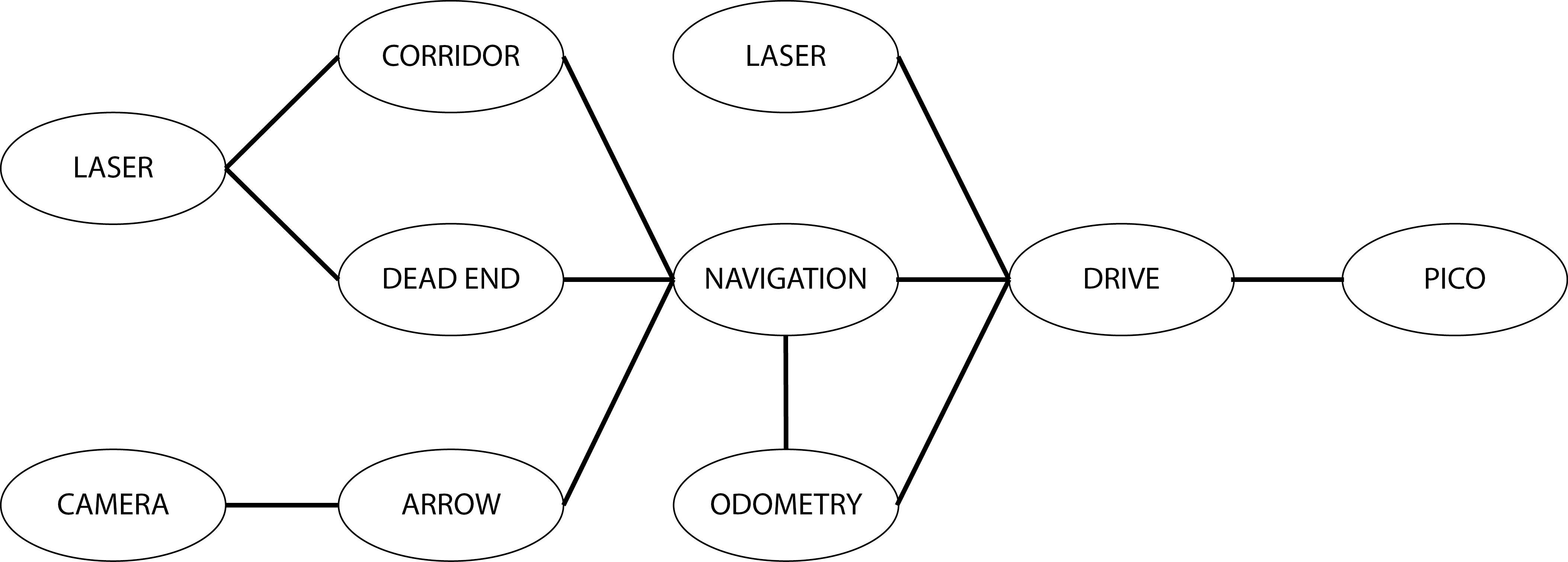
This week we started with designing the proper framework for the different Ros Nodes and Ros Messages. Each node has a specific function and a predefined interface.

arrow detect
The image topic in demo_opencv needs to be changed.
scanxy and straightdetect

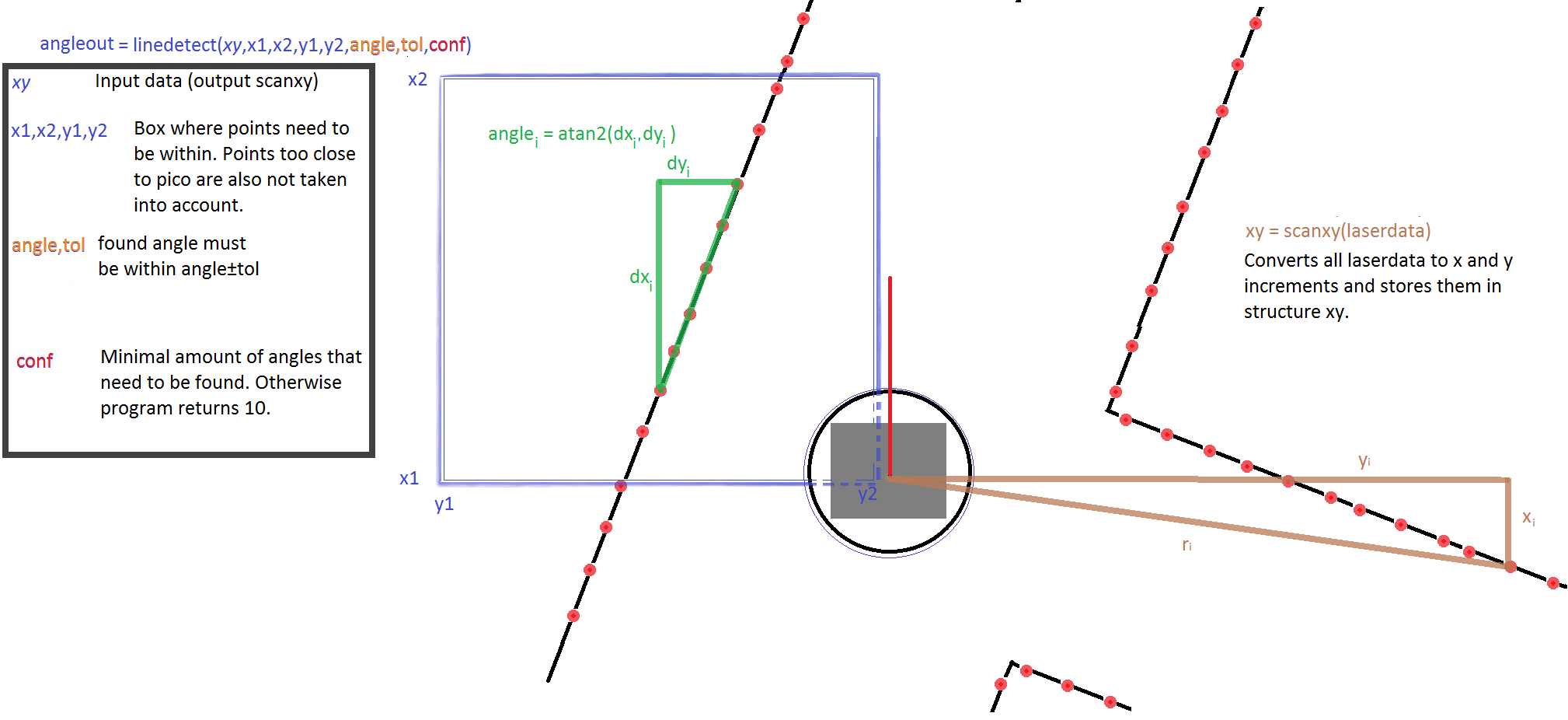
For the detection of the world and the desired direction, two scripts have been implemented. These two are visualised in the figure.
Scanxy; (purple lines)
This function reviews the laserdata and tranlates them to a structure with their x and y distance with respect to pico.
== Straightdetect; (other lines) ==
This function uses the result of scanxy, a struct of x and y coordinates. It analyzes the direction of the corridor with respect to the orientation of pico. It does this by looking at 2 laser points and comparing the dx and dy to calculate an angle. For robustness this process is repeated for multiple pairs of dots, the results are filtered and averaged. This results in a good and robust measurement of the angle which pico could rotate to be located straight in the corridor.