Embedded Motion Control 2018 Group 8: Difference between revisions
| Line 292: | Line 292: | ||
=== Mapping === | === Mapping === | ||
One part of the hospital challenge is to make a map of the entire hospital. In order to complete this task a mapping skill was added to the software. Based the room by room concept of the worldmodel, the map will also be build room by room. These separate maps will be combined to a full map of the hospital. The maps will be stored in the worldmodel in a seperate class. This class will contain all the information of the maps of each of the rooms. The map building functions are stored in a separate executable that can be called by the main function. | One part of the hospital challenge is to make a map of the entire hospital. In order to complete this task a mapping skill was added to the software. Based the room by room concept of the worldmodel, the map will also be build room by room. These separate maps will be combined to a full map of the hospital. The maps will be stored in the worldmodel in a seperate class. This class will contain all the information of the maps of each of the rooms. The map building functions are stored in a separate executable that can be called by the main function. | ||
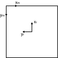
The image is made using openCV in c++. The image is represented as a matrix and its entries represent the pixels of the image. The image will contain all the walls of the rooms of the hospital. The walls of the rooms are made by checking which nodes are connected to each other. Then these nodes are used as endpoints for the openCV line element and is stored in the matrix. Since the coordinates of the nodes are given in Pico's coordinate frame, these have to be transformed into the matrix coordinate frame. This transformation is done via a rotation matrix over | The image is made using openCV in c++. The image is represented as a matrix and its entries represent the pixels of the image. The image will contain all the walls of the rooms of the hospital. The walls of the rooms are made by checking which nodes are connected to each other. Then these nodes are used as endpoints for the openCV line element and is stored in the matrix. Since the coordinates of the nodes are given in Pico's coordinate frame, these have to be transformed into the matrix coordinate frame. This transformation is done via a rotation matrix over <math>\frac(-\pi)(2)</math> | ||
[[File:EMC_Coordinate.png]] | [[File:EMC_Coordinate.png]] | ||
Revision as of 09:10, 19 June 2018
Group members
| Name: | Student id: | |
| Srinivasan Arcot Mohanarangan (S.A.M) | s.arcot.mohana.rangan@student.tue.nl | 1279785 |
| Sim Bouwmans (S.) | s.bouwmans@student.tue.nl | 0892672 |
| Yonis le Grand | y.s.l.grand@student.tue.nl | 1221543 |
| Johan Baeten | j.baeten@student.tue.nl | 0767539 |
| Michaël Heijnemans | m.c.j.heijnemans@student.tue.nl | 0714775 |
| René van de Molengraft & Herman Bruyninckx | René + Herman | Tutor |
Initial Design
The initial design file can be downloaded by clicking on the following link:File:Initial Design Group8.pdf.
A brief description of our initial design is also given below in this section. PICO has to be designed to fulfill two different tasks, namely the Escape Room Competition (EC) and the Hospital Competition (HC). When either EC or HC is mentioned in the text below, it means that the corresponding design criteria is only needed for that competition. If EC or HC is not mentioned, the design criteria holds for both challenges.
Requirements
An overview of the most important requirements from Main page:
- No "hard" collisions with the walls
- Find and exit the door of a room
- Fulfill the task within 5 minutes (EC)
- Do not stand still for more than 30 seconds
- Fulfill the task autonomously
- Map the complete environment (HC)
- Reverse into wall position behind the starting point after an exploration of the environment (HC)
- Find a newly placed object in an already explored environment (HC)
Functions
These were the initial functions we identified on a high level:
- Driving
- Translating
- Rotating
- Comparing Data
- For trajectory planning
- For newly placed object recognition
- Line fitting (least squares in C++)
- Trajectory and action planning
- Configuration
- Coordination
- Communication
- Mapping
- Parking
Components
| Component | Specifications |
| Computer |
|
| Sensors |
|
| Actuator | Holonomic vase (omni-wheels) |
| Soft Ware Modules |
|
Specifications
\item Maximum translational speed of 0.5 m/s \item Maximum rotational speed of 1.2 rad/s \item Translational distance range of 0.01 to 10 meters \item Orientation angle range of -2 to 2 radians or 229 degrees approximately \item Angular resolution of 0.004004 radians \item Scan time of 33 milliseconds
Interfaces
Task Skill Motion
Escape Room Competition
For the Escape Room Competition, a simple algorithm was used as code. This was done so that the group members without much C++ programming experience could get used to it while the more experienced programmers already worked on the perception code for the Hospital Competition. Therefore, the code used for the Escape Room Competition was a little bit different than the initial design because the aimed perception code was not fully debugged before the Escape Room Competition so that it could not be implemented in the written main code for the Escape Room Competition.
World Model
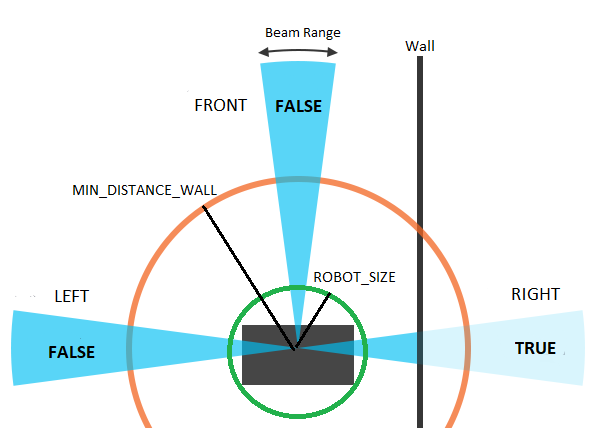
The data stored in the World Model is small and consists of only three boolians. Those concepts are left, right and front and gets either the value TRUE or FALSE depending on if a obstacle is near that side of the robot. The value of each concept will get refreshed with a frequency of FREQ, deleting all the old data so that no history is stored.
Perception
For the perception of the world for PICO, a simple space recognition code was used. In this code, the LRF data is split into three beam ranges. A left beam range, a front beam range and a right beam range. Around PICO, two circles are plotted. One is the ROBOT_SIZE circle which has a radius so that PICO is just encircled by the circle. The other circle is the MIN_DISTANCE_WALL circle which has a bigger radius than the ROBOT_SIZE circle. For each of the three laser beam ranges, the distance to an obstacle is checked for each beam, and the lowest distance which is larger than the radius of the ROBOT_SIZE circle is saved and checked if it is smaller than the radius of the MIN_DISTANCE_WALL circle. If that is true, the value TRUE is given to the corresponding laser beam range, else the value FALSE is given to that laser beam range. This scan is done with a frequency of FREQ, and by each scan, the previous values are deleted.
Monitoring
For the Escape Room Competition, PICO would only monitor its surroundings between the ROBOT_SIZE circle and the MIN_DISTANCE_WALL circle by giving a meaning to its sensor data (Left, Right, Front). The four meanings are:
- Nothing: All sensor data has the value FALSE
- Obstacle: At least one of the sensors has the value TRUE
- Wall: The Right sensor has value TRUE, while the Front sensor has value FALSE
- Corner: The Right and Front sensor has value TRUE
The monitored data is only stored for one moment and the old data is deleted and refreshed with each new dataset.
Planning
For the planning, a simple wall following algorithm is used. As design chose, the right wall is chosen as the wall to follow. As initial state it is assumed that PICO sees nothing. PICO will than check if there is actually nothing by searching at its position for an obstacle. If no obstacle is detected at its starting position, PICO will hypothesize that there is an obstacle in front of him and will drive forward until he has validated its hypothesis by seeing an obstacle. This hypothesis will always come true at a certain moment in time due to the restrictions on the world PICO is put into, only if PICO is already alligned to the exit, PICO will fullfill its task directly without seeing an obstacle..
As soon as an obstacle is detected, PICO will assume that this obstacle is a wall and will rotate counter-clockwise until its monitoring says that this obstacle is a wall, so that only the right sensor gives the value TRUE. Due to the fact that the world only consists of walls and corners, and corners are build out of walls, this hypothesis will again always come true when rotating. As soon as only a wall is detected, PICO will drive forward to keep the founded wall on the right.
While following the wall, it can happen that PICO will detect a corner if the front sensor goes of. This can happen if PICO is actually in a corner, or if PICO is not good alligned with the wall so that the front sensor sees the wall that PICO is following. However, in both cases, PICO will rotate counter-clockwise until he only sees a wall so that it will be beter alligned with the wall it was following or if PICO is actually in a corner, it will allign with the other wall that makes up the corner than the wall he was initially following and starts to follow that wall.
Another possibility that can happen if PICO is in its follow the wall state is that PICO lost the wall. This can again happen if PICO is not good alligned with the wall, or if there is an open space in the wall which is a door entry. In both cases, PICO rotates clockwise so that it initially sees a wall or a corner and than starts again following them as usual.
Driving
The Driving for the escaperoom challenge is reletivly simple. PICO has three drives states which are drive_forward, rotate_clockwise and rotate_counterclockwise. Depending on the monitoring, the planning will give which driving state needs to be done by PICO.
The values
The results
More / list on the differences with initial idea
Lessons learned
Hospital Competition Design
World Model
Our strategy is to store the least information as possible, since with less data the system is simplier and most likely more robust. In the worldmodel all the necissary information is stored for the four main functions of the program (perception, monitoring, planning and driving ). This way, there is no communication between the individual functions. They take the worldModel as input, do operations and store data to the worldmodel. The main object in the worldmodel is the rooms vector, which contains all the rooms. In this subclass all the perception and monitoring data regarding that room is stored. So it contains a list of all doors in the room and of all the nodes in the room. The worldmodel also contains flags for the planning and the driving such as it's current task and it's current driving skill.
Nodes
A node is a class containing the data on the (possible) corners. This contains the position of the point (in x and y) relative to Pico. And the 'weight' of the node is stored, this is how many times this node has been perceived. This value comes in to play to hypothesis whether or not this node is a actual corner. To categorize the different types of nodes the following Boolean attributes of the node objects are stored:
| Node type | Subtype | Definition |
| Open Node | The unconfirmed end of a line | |
| closed Node | Inward Corner | Confirmed intersection of two lines.The angle the node vector (which is always relative to PICO) and each of the intersecting lines is less than 90 degrees at moment of detection. |
| Outward corner | Confirmed intersection of two lines.The angle the node vector (which is always relative to PICO) and at least one of the intersecting lines is more than 90 degrees at moment of detection. |
Doors
The doors contain the points from where to where Pico should drive to enter and exit a room. These point are stored as nodes and can be called by the planning to determine the setpoint for the driving skill.
Room
A room consists of a number of nodes and a list of the existing connections. The room thus contains a vector of nodes. Room nodes are updated until the robot leaves the room. The coordinates are than stored relative to the door. This is further described under monitoring. There are two types of hypothesized doors. The strongest hypothesized door is identified by at least one outward corner. The other is identified as adjacent to an open node.
Perception
Firstly the data from the sensors is converted to Cartesian coordinates and stored in the LaserCoord class within Perception. From the testing it became clear that Pico can also detect itself for some data points and that the data at the far ends of the range are unreliable. Therefor the attribute boolean Valid in LaserCoord is set to false in those cases. When using the data it can be decided if the invalid points should be ex- or included.
For the mapping, the corner nodes and nodal connectivity should be determined as defined in the worldmodel. To do this, the laser range data will be examined. The first action is to do a "split and merge" algorithm where the index of the data point is stored where the distance between to points is larger than a certain threshold. The laser scans radially, therefor the further an object is, the further the measurements differ from each other in the Cartesian system. The threshold value is therefor made dependent on the polar distance.
The point before and after each split is hypothesized as a outward corner. This might be a corner, but can also be part of a (unseen) wall. The corner is stored as a invalid node, until it is certain that it is actual outward corner.
Old method
Then in the section between splits the wall is consecutive, however there could be corners inside that section. These corners need to be found.
The original idea was to check if the lines at the begin and end of the section with three hypothesis:
- They belong to the same line. No further action
- They are parallel lines. Two corners must lay in this section. Do a recursive action by splitting the section in two.
- To different lines. The intersection is most likely a corner.
To determine the lines a linear least squares method is used. This is done for a small selection of points at the beginning and the end of the section. If the error from the fit is too large the selections of points is moved until the error is satisfied.
This method proved to be not robust. For horizontal or vertical fits the lines y=ax+b do not produce the correct coefficients. Even with a swap, so x=ay+b this method fails in some cases. It would probably be possible to continue with this method, but it is decided to abandon this search method within the section and adopt to an alternative. This will be a good example of a learning curve.
Current implementation
The method which is currently implimented is inspired by one of last years groups: link to Group 10 2017. The spit and merge can stay in place, the change is the "evaluate sections" function.
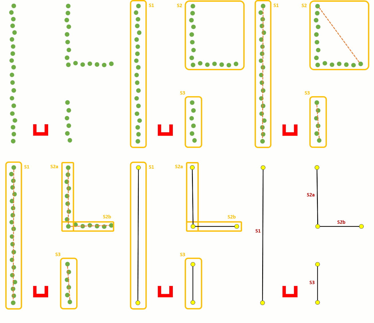
Monitoring
The monitoring stage of the software architecture is used to check if it is possible to fit objects to the data of the perception block. For instance by combining four corners into a room. The room is then marked as an object and stored in the memory of the robot. The same is done for doors. This way it is easier for the robot to return to a certain room instead of exploring the whole hospital again. Monitoring is thus responsible for the creation of new room instances, setting of the room attribute explored to 'True' and maintaining the hypotheses of reality. Also the monitoring skill will send out triggers for the planning block if a room is fully explored. It also keeps track of which doors are already passed and which door leads to a new room.
The functions of monitoring are:
- Door detection
- Room fully explored
- Hospital fully explored
- Hypotheses
Door detection
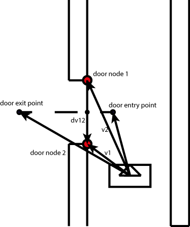
The door detection function uses the information that is stored in the worldmodel to make a door object of two nodes. The function checks for several properties that two nodes have to have to be qualified to be a door.
Node properties:
- One node is an outward corner the other one can be a end node or open node.
- Distance between them is 0.5 to 1.5m.
- The two nodes are not connected by a wall.
- The door has to be either aligned (within bounds) with the x or the y axis of the robot.
The door is defined by two outward facing corners to the robot, but this is actually not necessary. One of the two corners can be an open node, i.e. an unexplored node. In this way the system can recognize doors in walls that the robot did not fully explore and therefore requires less information. The choice of only detecting doors that are aligned with the x or y axis of the robot reduced the amount of false positive matches that were encountered during testing, because in the beginning it made doors across the hallway if there were two doors opposite each other.
When the nodes fulfil all the properties a new door is stored in the current room. This door is marked unexplored so the planning skill knows where to go to. Also an entry point and an exit point are saved with the door. These points are used to safely drive the robot through the door.
Room fully explored
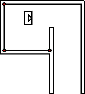
The current room that the robot is in is marked as explored when there are three inward corners found in the room. The choice to make the room explored when there are three corners and not four is that it might happen that the entrance to the room is not in the middle of a wall, but at one of the ends and then the room consists of three corners and not four.
Hospital fully explored
The hospital is marked as fully explored when the hallway has no more unexplored doors and has no more open nodes. An open node is an undefined node, so it is neither a corner or an endpoint of a wall. In this way the robot will keep on exploring the hallway until it has verified all nodes.
Hypotheses:
When mapping the room the code will maintain two hypothesis of it's reality. The perceived map as described in perception is assumed to be spatially accurate. However PICO is not able to detect and perceive nodes that are behind it. Furthermore perception happens near continuously at 20 Hz. In that time PICO is able to detect which newly found nodes correspond to nodes already stored in memory by checking the distance between the old and the new node. This comparison is less robust when PICO is moving due to larger discrepancies in distance between an the old and new position of a node. For this reason PICO also maintains an odometery-based hypothesis. New positions of the nodes are predicted based on odometer signal and than compared with the perceived nodes to determine which perceived node position correspond to those in memory. Based on this the actual translation and rotation can be determined with three corresponding nodes using the following formula. These nodes need to be in front of PICO to ensure that they are not false-positives:
[math]\displaystyle{ \begin{bmatrix} T \end{bmatrix} = \begin{bmatrix} x_{1,t-\Delta t} & y_{1,t-\Delta t} & 1 \\ x_{2,t-\Delta t} & y_{2,t-\Delta t} & 1 \\ x_{3,t-\Delta t} & y_{3,t-\Delta t} & 1 \\ \end{bmatrix}^{-1} \cdot \begin{bmatrix} x_{1,t} & y_{1,t} & 1 \\ x_{2,t} & y_{2,t} & 1 \\ x_{3,t} & y_{3,t} & 1 \\ \end{bmatrix} }[/math]
Here T is the transformation matrix. The first matrix consists of the x and y coordinates at a previous time step, the second matrix contains the corresponding positions at current time. The transformation matrix is than used to update all the actual room object contained in our world model.
Planning
Driving
Mapping
One part of the hospital challenge is to make a map of the entire hospital. In order to complete this task a mapping skill was added to the software. Based the room by room concept of the worldmodel, the map will also be build room by room. These separate maps will be combined to a full map of the hospital. The maps will be stored in the worldmodel in a seperate class. This class will contain all the information of the maps of each of the rooms. The map building functions are stored in a separate executable that can be called by the main function. The image is made using openCV in c++. The image is represented as a matrix and its entries represent the pixels of the image. The image will contain all the walls of the rooms of the hospital. The walls of the rooms are made by checking which nodes are connected to each other. Then these nodes are used as endpoints for the openCV line element and is stored in the matrix. Since the coordinates of the nodes are given in Pico's coordinate frame, these have to be transformed into the matrix coordinate frame. This transformation is done via a rotation matrix over [math]\displaystyle{ \frac(-\pi)(2) }[/math]
The mapping section has the following functions:
- Map_init
- Map_room
- Map_hospital
- Map_show
Map init This function initilizes the openCV matrix.
Group Review
Results and Discussion
From the start of the project we had all agreed upon the general direction of our design. However partly due to inexperience with programming in C++ we were hesitant to start coding until we had consensus on the exact details of our software architecture. Because of this integration of the software started relatively late resulting in a code that was not fully tested on the day of the challenge. For this reason we were not able to demonstrate the full capability of our design.
We are proud of our extensive design. Our mapping oriented around the determining of landmarks (nodes) which were robustly maintained using multiple hypotheses. All nodes and destinations where stored relative to PICO using no more information than necessary. Our state-machine had a concise logical structure and could determine the next action in a simple and yet robust manner. All relevant information was communicated with the world model. This contained extensive information about the surrounding such as doors, connectivity between the rooms and the next destination.
For the escape room challenge we had a simple implementation of a Wall follower algorithm. We were one of the only three groups to successfully get the robot moving towards the exit. This was also due to our groups early mastery of the git protocol. We had no trouble pulling the code to PICO.
Recommendations
We have a few major recommendations for any group of experienced coding. First, start practicing writing code within the first week of the project. Second have an extensive conversation within the first two weeks of the project. Don´t get stuck to long on details of the design but quickly divide the work and start implementation. Making an extensive design of the data structure is difficult without previous experience. This leads to a "chicken and egg" question where uncertainty in design decisions arises from a lack of experience. For this reason it is impractical to take the linear 'waterfall model' in which implementation coming after design. Instead take the 'agile' or 'concurrent design' approach where implementation and design are done intermittently. Design decisions will become more evident after having coded. Use a modular code structure that can be easily changed. Make each team member in charge of a single module and continuously communicate on the inputs and outputs needed for each module. Flexibility and communication is key. Trying to code is more important than having a complete picture of what you are going to do beforehand.
Code snippets
The first snippet we like to share is our main function. We used the guidelines for a clean robot program as presented by Herman Bruyninckx. We don't need all the function that were presented. The communication is not needed as a separate function, because this is included in the EMC library. Configuration is not a separate function because all the parameters are set to be constant and can be adjusted in the config.h file. We do have computations which can be subdivided into perception, monitoring and planning. Using these guidelines a structured main file is created which is easy to understand. To further improve performance it would be possible to do certain functions at a higher or a lower rate. This can easily be done by only executing for example the the monitoring and the planning every xth loop.
Secondly, the worldmodel is presented. here the data is actual stored as reported in this page. Most functions are there just to store and to fetch data from the private member attributes, but some do some (small) computations on that data. The larger functions like "add_Node" are in the .c file as to not clutter the header file.
In the perception we implemented a split and merge algorithm. The "evaluateSections" function then finds all corners which are present in that section (of the LRF data) and stores it in the worldmodel. Some clever functionality is a recursive function, so no matter how many corners there are in a section the program will find all. If no new corners are found it can be concluded that:
- 1. the nodes are connected
- 2. there is no corner in between the nodes
Therefor a line drawn between the two nodes can be considered a wall.
