Embedded Motion Control 2013 Group 2: Difference between revisions
| Line 268: | Line 268: | ||
|- | |- | ||
|[[File:Localization.pdf]] | |[[File:Localization.pdf]] | ||
|- | |||
|- | |||
| '''Corner Detection Algorithm''' | |||
| | |||
|- | |||
| For the mapping of the environment a function has been created in order to detect the edges of the maze. Before the detection algorithm was build the following requirement to the algorithm were made: | |||
The corner detection function should: | |||
• Detect corners / edges. | |||
• Detect corner types. | |||
• Store locations and types. | |||
| | |||
|- | |||
| The different corner types are divided into a number of types. In order to identify the type of each corner the following type-names have been given to the numbers by using an enumerate. | |||
1. Left_outside | |||
2. Left_inside | |||
3. Right_inside | |||
4. Right_outside | |||
5. Blind_left | |||
6. Blind_right | |||
7. Leftback_inside | |||
8. Leftback_outside | |||
9. Rightback_inside | |||
10. Rightback_outside | |||
| | |||
|- | |||
|For each type of corner can be specified by using the measuring data. The localization provides the angle of the robot in relation the corridor. So first all the laser data of the robot are converted into x and y coordinates in relation to the robot. With the angle of the robot in relation to the corridor the measured x and y position are translated into the coordinate system parallel to the corridor. The new y direction lies parallel to the heart line of the corridor and the new x direction lies perpendicular to the heart line of the corridor. These new coordinates are called the normalized coordinates. With these normalized coordinates the position of the edge are calculated. The positions of the edges are later on translated back to the robot coordinate system. | |||
With the normalized coordinates the direction of the wall is determined. A wall can go vertical or horizontal within certain margins / deviations. For the detection of the different types of edges the difference is made between vertical_up, vertical_down, Horizontal_left and Horizontal_right. When the normalized y-coordinate becomes larger than the defined margin the direction vertical_up is detected, when the normalized y-coordinate becomes smaller the direction vertical_down is detected. (These names are chosen due to the top-view of the situation.) The algorithm to determine the corners will use these directions. | |||
When the measured direction changes, there must have been an edge (assuming no errors). Since there are errors in the environment (by example: gaps between walls) and the measurements, certain margins are applied to avoid that due to the errors edges are detected. The algorithm checks whether the previous point lies within a certain margin of the current point. The check considers the normalized x and y direction of the point. If by example the current direction is horizontal the normalized y values should be constant (within the margin). If the change in normalized y values changes to much (more than the margin) the direction is changed. By checking the normalized x value the new direction can be determined (vertical_up or vertical_down). This results in a corner type (one or three) and a corner location (in normalized coordinates). | |||
In case of the corner types 5 and 6, the blind corners, new values of both x and y are outside the margin. This means that blind corner has been found. | |||
| | |||
|- | |||
|As can be seen in the figure, a clear jump in measured coordinates can be detected. The new direction is now unknown, since the direction of the wall detected behind the blind edge is yet unknown. The next normalized coordinate will show whether the newly detected wall is vertical or horizontal and set the new direction. When a jump in measurement data is detected, depending whether the coordinates have become closed or further to the robot determines the different between type 5 and 6. | |||
| | |||
|- | |- | ||
|'''Corridor competition''' | |'''Corridor competition''' | ||
Revision as of 14:18, 2 October 2013
Group Members
| Name: | Student id: | Email: |
| Joep Alleleijn | 0760626 | j.h.h.m.alleleijn@student.tue.nl |
| E. Romero Sahagun | 0827538 | e.romero.sahagun@student.tue.nl |
| L. Galindez Olascoaga | 0867854 | l.i.galindez.olascoaga@student.tue.nl |
| Koen Meeusen | 0657087 | k.a.meeusen@student.tue.nl |
| Ngo Hin Cheng | 0731296 | n.h.cheng@student.tue.nl |
Planning
| Week: | Activities: |
|---|---|
| Week 1: Sep 2 - Sep 8 | |
| Start ROS & C++ tutorials | |
| Prepare software (Ubuntu, ROS, Gazebo, etc..) | |
| Project planning & brainstorming | |
| Week 2: Sep 9 - Sep 15 | |
| Conclude software troubleshoot. | |
| Start simulations in Gazebo for sensors and actuators identification. | |
| Week 3: Sep 16 - Sep 22 | |
| Code development, module based. | |
| Code implementation for Corridor Competition, tests on simulation. | |
| First real robot trial (Sep 20, 13.00 - 14:00 hrs) | |
| Week 4: Sep 23 - Sep 29 | |
| Last minute preparations for Corridor Competition | |
| Second real robot trial (to schedule..) | |
| Corridor Competition (Sep 25) | |
| 2nd Real robot test (Sep 26, 11.00 - 12:00 hrs) | |
| Week 5: Sep 30 - Oct 6 | |
| 3rd Real robot test (Oct 3, 11.00 - 12:00 hrs) | |
| Week 6: Oct 7 - Oct 13 | |
| 4th Real robot test (Oct 10, 11.00 - 12:00 hrs) | |
| Week 7: Oct 14 - Oct 20 | |
| 5th Real robot test (Oct 17, 11.00 - 12:00 hrs) | |
| Week 8: Oct 21 - Oct 27 | |
| Maze Competition (Oct 23) |
Current Work
| Team Member: | Working on: |
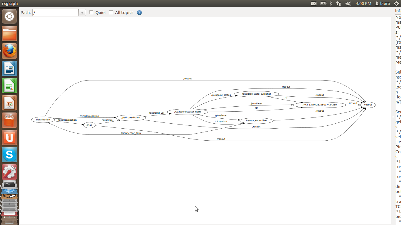
| Joep Alleleijn | System architecture, message structure between nodes-> which information is communicated and how. Determine location within the environment based on laser data, build in functionality so it still works when there is an opening in the maze. |
| E. Romero Sahagun | Movement module/functions (move forward, backward, turn left/right) |
| L. Galindez Olascoaga | System architecture, interfaces and integration/path planning algorithm |
| Koen Meeusen | Wall and corner detection, area mapping. |
Progress
Week 1: September 2 - September 8
| Software installation |
| The goal of the first week was to install all necessary software. The installation of Ubuntu went well in general. In one case (on the 2013 TU/e laptop) Ubuntu would install correctly (it said) but when Ubuntu was started the desktop screen of Ubuntu was not loaded. Instead a command prompt like screen was displayed and reports where shown that there were missing files. The problem was eventually solved as follows:
In case the laptop has been fitted with a small ssd parallel to the main harddisk (like the 2013 TU/e laptop), Ubuntu will not install properly. Because the ssd-drive and the harddisk are placed parallel the laptop will start faster since the ssd provides a fast start-up. When Ubuntu starts it requires files which are not present on the ssd, which causes Ubuntu to fail. The solution is to disable the raid configuration of the laptop. This disables the ssd-drive and its advantages but Ubuntu will start now since all the required files are received from the harddisk. In some cases the Raid is called Intel RST (rapid storage technology). Switching of the raid system in BIOS might result in losing your windows and all your data on the disk. So it is not recommended ( We have never tried it before). Login in windows and open the Intel Rapid Storage Technology program and disable raid support in a less brutal way to avoid such risks. The other required software installed well except Qt. By a few persons Qt did not install. Therefore the choise has been made to use eclipse to type the c++ code. The disadvantage is that in eclipse you will have to rebuild your “cmake” and project files every time you change something in the script. This requires a restart of eclipse. Qt does not have this problem. An advantage of eclipse over Qt is that eclipse can handle vector programming easier then Qt. |
| Problem investigation |
| In order to solve the maze problem some important questions had to be answered, namely:
- Is the maze unique? (In other words, is there only one solution?) - Are there island in the maze? (walls which are not connected to the outside of the maze) The answered to these questions are yes, the maze is unique and no, there are no island. With these questions answered a simple strategy has been made to solve the maze: If the maze contains islands the solution won’t be totally unique, because there are multiple ways to solve the maze. With islands it is even possible to get stuck in a loop around the island in the maze. With only one path which is correct (a unique solution) and no islands a solution to the maze can be to follow the right hand wall of the robot. In case of the corridor challenge, the solution is not unique, since there are to exits (a correct one and a false one). Although the strategy to follow the right hand wall will in this case give the correct solution. Besides more advances technique to solve a maze, this solution can easily be programed and can be used for testing the simulator. The goal is to have a more advanced maze solving algorithm for the corridor test. However this has to be developed yet. |
Week 2: September 9 - September 15
| Testing laser data acquisition | ||||||||||||||||||||||||||||||||||||||||||||||||||||||||||||||||||||||||||||||||||||||||||||||||||||||||||||
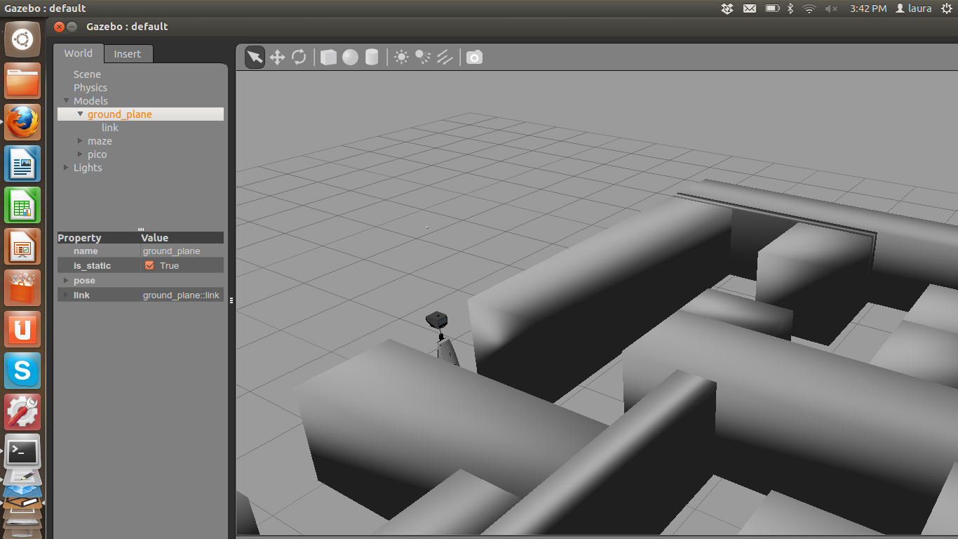
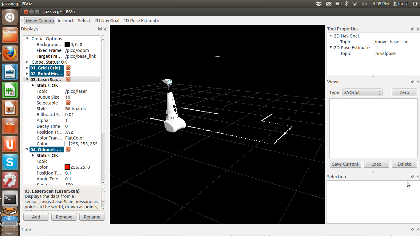
| Simulated laser data (Laura and Joep) | ||||||||||||||||||||||||||||||||||||||||||||||||||||||||||||||||||||||||||||||||||||||||||||||||||||||||||||
Structure message from laser:
Week 3: September 16 - September 22Week 4: September 23 - September 29
Week 5: September 30 - October 6
Week 6: October 7 - October 13
Doubts & Questions
FAQ & Doubts |


