Embedded Motion Control 2013 Group 8: Difference between revisions
| Line 111: | Line 111: | ||
[[File:Range_diff_outlier.png|thumb|left|500x250px]] [[File:Gap_location_definition.png|thumb|right|500x250px]] | |||
===Gapdetection=== | |||
'''''Input:''''' Laser_vector[1081] | '''''Input:''''' Laser_vector[1081] | ||
'''''output:''''' gap location [float x1; float x2; float xm; float y1; float y2; float ym] | '''''output:''''' gap location [float x1; float x2; float xm; float y1; float y2; float ym] | ||
| Line 117: | Line 118: | ||
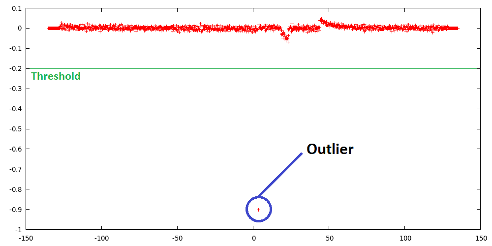
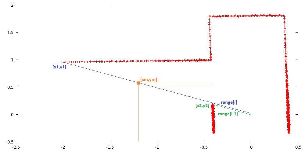
A gap is detected by thresholding the derivative of the laser ranges, this derivative is defined as the difference of laser range [i] and [i-1]. If this difference is larger than the threshold, laser range [i] and [i-1] are labeled as gap corners. The function then starts calculating the position of these laser reflection points relative to its own position. The corner closest to the robot is labeled as point1 [x1,y1] and the other as point2 [x2,y2], the function also outputs the euclidean middle of both points [xm,ym]. | A gap is detected by thresholding the derivative of the laser ranges, this derivative is defined as the difference of laser range [i] and [i-1]. If this difference is larger than the threshold, laser range [i] and [i-1] are labeled as gap corners. The function then starts calculating the position of these laser reflection points relative to its own position. The corner closest to the robot is labeled as point1 [x1,y1] and the other as point2 [x2,y2], the function also outputs the euclidean middle of both points [xm,ym]. | ||
===Relative location=== | ===Relative location=== | ||
Revision as of 13:20, 23 September 2013
Group members
| Name: | Student id: | Email: |
| Robert Berkvens | s106255 | r.j.m.berkvens@student.tue.nl |
| Jorie Teunissen | s102861 | j.a.m.teunissen@student.tue.nl |
| Martin Tetteroo | s081356 | m.tetteroo@student.tue.nl |
| Rob Verhaart | s080654 | r.a.verhaart@student.tue.nl |
Tutor
| Name: | Email: |
| Rob Janssen | r.j.m.janssen@.tue.nl |
Minutes
Planning
Week 1 (02-09-2013 - 08-09-2013)
- Installing software
- Following tutorials
- Setup SVN
Week 2 (09-09-2013 - 15-09-2013)
- Installing Jazz simulator
- Brainstorm on functions
- Setting up plan of approach
- Martin: Measure middle road driving
Week 3 (16-09-2013 - 22-09-2013)
Week 4 (23-09-2013 - 27-09-2013)
- September 25th Corridor Challenge
Week 5 (30-09-2013 - 04-10-2013)
Week 6 (07-10-2013 - 11-10-2013)
Week 7 (14-10-2013 - 18-10-2013)
Week 8 (21-10-2013 - 25-10-2013)
- October 23th Final Challenge
Strategy
Modules:
- Corridor detection
- Relative location in corridor
- map
- route calculation
- Speed/angle regulator
- safety node
- arrow node
Corridor detection
This function detects all the walls. The walls are outputted as line segments in x,y coordinates.
Input: Laser_vector[1081] output: Vector[Lines], with lines[float x_begin; float y_begin; float x_end; float y_end]


Gapdetection
Input: Laser_vector[1081] output: gap location [float x1; float x2; float xm; float y1; float y2; float ym]
A gap is detected by thresholding the derivative of the laser ranges, this derivative is defined as the difference of laser range [i] and [i-1]. If this difference is larger than the threshold, laser range [i] and [i-1] are labeled as gap corners. The function then starts calculating the position of these laser reflection points relative to its own position. The corner closest to the robot is labeled as point1 [x1,y1] and the other as point2 [x2,y2], the function also outputs the euclidean middle of both points [xm,ym].
Relative location
This function calculates the distance from the wall on the left and on the right and the angle of the robot towards these walls.
Input: Laser_vector[1081], Vector[Lines] Output: Location_rel[ float Dist_left; float dist_right, int Theta]
Map
Using the results of the previous modules this module will update the current map. The location of the robot and the walls/corners/deadends will be drawn in the map. The starting point of the map (0,0) is the start point of the robot. So every time the map from this point will be calculated. As an improvement a particle filter might be needed to draw a better map.