Drone Referee - MSD 2017/18: Difference between revisions
| Line 551: | Line 551: | ||
There are different methods for interaction with dynamic simulation. This article describes some of the ways in which you can utilize Simulink’s data in MATLAB GUI. Simulink Function, Simulink Call back Functions, Simulink Event Listener, Custom MATLAB Code S-Function and Gluing the Simulink with GUIDE are some of the methods that can be used for this purposes. However, this documentation does not intend to explore every option in detail. | There are different methods for interaction with dynamic simulation. This article describes some of the ways in which you can utilize Simulink’s data in MATLAB GUI. Simulink Function, Simulink Call back Functions, Simulink Event Listener, Custom MATLAB Code S-Function and Gluing the Simulink with GUIDE are some of the methods that can be used for this purposes. However, this documentation does not intend to explore every option in detail. | ||
To avoid future confusion, some of the experimented NON real-time methods for information collecting from Simulink model is explained as follow: | To avoid future confusion, some of the experimented NON real-time methods for information collecting from Simulink model is explained as follow: | ||
=====Non-real-time | =====Non-real-time solutions===== | ||
* Using To Workspace block to export the data.However, only data at the very beginning of the simulation can be extracted. | * Using To Workspace block to export the data.However, only data at the very beginning of the simulation can be extracted. | ||
Revision as of 15:53, 20 April 2018
Introduction
Abstract
Being a billion Euro industry, the game of Football is constantly evolving with the use of advancing technologies that not only improves the game but also the fan experience. Most football stadiums are outfitted with state-of-the-art camera technologies that provide previously unseen vantage points to audiences worldwide. However, football matches are still refereed by humans who take decisions based on their visual information alone. This causes the referee to make incorrect decisions, which might strongly affect the outcome of the games. There is a need for supporting technologies that can improve the accuracy of referee decisions. Through this project, TU Eindhoven hopes develop a system with intelligent technology that can monitor the game in real time and make fair decisions based on observed events. This project is a first step towards that goal.
In this project, a drone is used to evaluate a football match, detect events and provide recommendations to a remote referee. The remote referee is then able to make decisions based on these recommendations from the drone. This football match is played by the university’s RoboCup robots, and, as a proof-of-concept, the drone referee is developed for this environment.
This project focuses on the design and development of a high level system architecture and corresponding software modules on an existing quadrotor (drone). This project builds upon data and recommendations by the first two generations of Mechatronics System Design trainees with the purpose of providing a proof-of-concept Drone Referee for a 2x2 robot-soccer match.
Background and Context
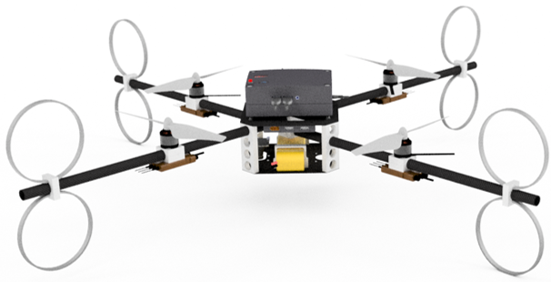
The Drone Referee project was introduced to the PDEng Mechatronics Systems Design team of 2015. The team was successful in demonstrating a proof-of-concept architecture, and the PDEng team of 2016 developed this further on an off-the-shelf drone. The challenge presented to the team of 2017 was to use the lessons of the previous teams to develop a drone referee using a new custom-made quadrotor. This drone was built and configured by a master student and his thesis was used as the baseline for this project.
The MSD 2017 team is made up of seven people with different technical and academic backgrounds. One project manager and two team leaders were appointed and the remaining four team-members were divided under the two team leaders. The team is organized as below:
| Name | Role | Contact |
|---|---|---|
| Siddharth Khalate | Project Manager | s.r.khalate@tue.nl |
| Mohamed Abdel-Alim | Team 1 Leader | m.a.a.h.alosta@tue.nl |
| Aditya Kamath | Team 1 | a.kamath@tue.nl |
| Bahareh Aboutalebian | Team 1 | b.aboutalebian@tue.nl |
| Sabyasachi Neogi | Team 2 Leader | s.neogi@tue.nl |
| Sahar Etedali | Team 2 | s.etedalidehkordi@tue.nl |
| Mohammad Reza Homayoun | Team 2 | m.r.homayoun@tue.nl |
Problem Description
Problem Setting
Two agents will be used to referee the game: a drone moving above the pitch and a remote human referee, receiving video streams from a camera-gimbal system attached to the drone. The motion controller of the drone and the gimbal must provide video streams allowing for an adequate situation awareness of the human referee, and consequently enabling him/her to make proper decisions. A visualization and command interface shall allow interaction between the drone and the human referees. In particular, besides allowing the visualization of the real-time video stream this interface shall allow for more features such as on-demand repetitions of recent plays and enable the human referee to send decisions (kick-off, foul, free throw, etc) which should be signaled to the audience via LEDs placed on the drone and a display connected to a ground station. Moreover, based on computer vision processing, an algorithm which can run on the remote PC showing the video stream to the human referee, shall give a recommendation to the human referee with respect to the following two rules:
- RULE A: Free throw, when the ball moves out of the bounds of the pitch, crossing one of the four lines delimiting the field.
- RULE B: When robot players in the pitch touch each other a potential foul can occur. Therefore, the system should detect and signal when two robot players in the pitch are touching each other.
If time permits, the remote referee can be given a recommendation by the autonomous system on more rules, such as the distance rules for free kicks mentioned before. The robot soccer field at the mechanical engineering department, building GEM-N, will be used to test the algorithms.
Goal
The final goal is to have a 5 minute long 2 against 2 robot soccer game, using the tech united turtles, refereed by the system described above, which receives a positive recommendation by the human referee. By positive recommendation we mean that the human referee acknowledges that the refereeing system provided, for that 5 minute long game, all the required information and recommendations that enabled him/her to make decisions which would be at least as good as he/she would make if physically present on the pitch. A member of tech-united, with previous refereeing experience, will be asked to referee the game at a different building (GEM-Z) based on the live stream and repetitions provided by the system. Another member of the tech-united will be responsible for simple tasks as placing the ball at the correct position for free-throws, free kicks, etc.
Workpackages
Four workpackages were defined in the problem statement. These were stated as guidelines to tackle the problem at hand. In addition, the team was given freedom to define their own approach to reach the goal. The four workpackages are defined below:
- WP1: Design and simulation of the motion planner and supervisory control
- WP2: Motion control of the drone and gimbal system
- WP3: Visualization and command interface
- WP4: Automatic recommendation for rule enforcement
Final Deliverables
- System architecture of the proposed solution by January 31st along with a time plan and task distribution for the members of the group
- Software of the proposed solutions
- Demo to be scheduled by the end of March or beginning of April
- A Wikipage documenting the project and providing a repository for the software developed, similar the one obtained from the first generation of MSD students
- One minute long video to be used in presentations illustrating the work
- 5 minute long video with the actual game, the remote referee visualizations and the audience screen visualizations
Project Scope
The scope of this project was refined during the design phase of the project. This was done due to considerable hardware issues and time constraints. The scope was narrowed down to the following deliverables.
- System Architecture
- Task-Skill-World model
- DSM
- Flight and Control
- Manual and Semi-Autonomous Flight
- Autonomous Flight
- Hardware and Software Interfaces
- Event Detection
- Ball-out-of-pitch Detection
- Collision detection
- Hardware and Software Interfaces
- Rule Enforcement and HMI
- Supervisory Control
- Referee/Audience GUI
- Hardware and Software Interfaces
- Demonstration Video and Final Presentation
- Wiki page
System Architecture
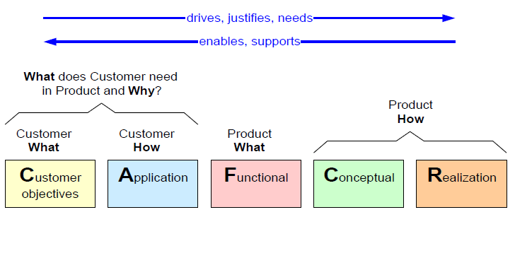
The initial architecture of Autonomous drone referee is based on CAFCR system architecture principles which follows the CAFCR: A Multi-view Method for Embedded Systems Architecting. Balancing Genericity and Specificity[1]. This architecting technique gave us an insight about different view-points in the project, and to create an architecture that has a balance between customer demands and the resources present.
Task Skill Motion Model
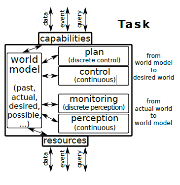
This is a paradigm quite often used to define system architecture of robotics systems. This paradigm is taken from Composable control stacks in component-based cyber-physical system platforms [2], it presents a model of components, whose final goal is to create a software application to be deployed on an operating systems process on top of a hardware resources. This model helps to realize the compositions required for an application to perform tasks and eventually multiple systems constitute a complete system. This model helps to realize certain aspects:
- It realizes the goals of the application
- It realizes how the goals will be realized
- How to exploit the resources it has available and construct model with that
- To realize capabilities that application can offer.
Components of the Task model:
- Resources: These are the limitations and constrains that are put up by the resources available for the project.
- Capability: The limitation of the task that can be achieved by a user from it.
- World Model: In a world model all the information is stored. It contains the past, present and future or the desired state of the tasks. The world model is required to be interconnected with other task models so as to share the information and also to update accordingly.
- Plan: The high level discrete events that makes the current world model to achieve the desired world model.
- Control: It consists of how to realize the plan, in the actual world, and with the actual task requirements and constraints. It contains continuous events facilitating the plans.
- Monitor: It is a check on the perception so as to monitor expected behavior of the tasks. The monitor triggers the control action to keep the task parameters in check.
- Perception: The perception is how the world model is perceived and updated in the world model.
Implemented Architecture and Description
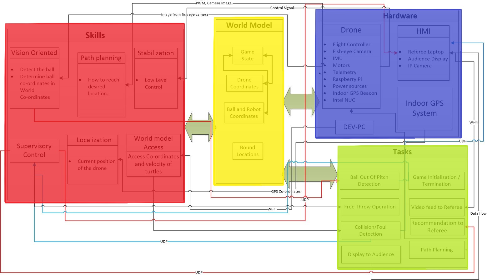
The architecture proposed has four prominent blocks: tasks, hardware, world model and skill. The tasks (green) consists of the objectives that is to be accomplished for the completion of the project. Skills (red) the implementation that is required perform the tasks successfully, this basically is the amalgamated version of the control and plan elements of the task skill motion model. Hardware (blue) block consists of all the hardware resources used in order to complete the tasks. It also has the platform where the tasks are performed, so the hardware is related to the capabilities of the system. So, hardware block in this architecture contains both resources and capabilities. World model (Yellow) acts as a dynamically updated data base for the parameters such as game states which informs about what is the current status of the game, for example if it is in a game play or a pause has been taken for decision enforcement. World model also stores and updates the ball and robot co-ordinates which are quite crucial for the collision detection and the ball out of pitch detection.
The architecture also consists of interfaces between the interlinked components in the system. These interfaces are marked with the kind of information flow between the blocks. The world model is kept connected to all the blocks because it needs to be dynamically updated with the all the information.
Hardware::
- Drones: The drone used was made by Peter Rooijaker (master student from TU/e) as his master thesis project here. The drone consists of a flight controller called pixhawk PX4, motors, fish eye, lidar, raspberry pi as an on-board processor for processing vision and indoor GPS beacon. Telemetry was used to communicate between drone and the off-board PC (Intel Nuc).
- Indoor GPS System: The localisation of the drone was done by installing Indoor GPS system by placing ultra sound beacons around the field. One of these beacons was placed on the drone which gave the drone co-ordinates.
- Dev-PC: We needed a Linux machine that can connect to the TechUnited network to access the world.
- Referee Laptop: A Laptop where a remote referee is monitoring the game and has an HMI to give his decision based on the recommendation and video feed.
World Model:
- Games States: It stores the state of the game if it's in progress, there is an event (ball out of pitch, ball inside pitch), there is a pause (referee taking time to think about discussion) or the game has ended.
- Drone Co-ordinates: It stores the co-ordinates of the drone obtained from the indoor GPS system and lidar.
- Ball and Robot Co-ordinates: The ball co-ordinates were obtained in the world model frame using fish eye camera and raspberry pi. The robot co-ordinates were obtained by accessing the TechUnited World model.
Task:The objectives of the system is explained here:
- Ball out of pitch': The system detects when the ball goes out of the pitch.
- Free throw: The referee notifies his decision of Free throw via HMI to the audience.
- Collision detection: The system is able to detect when two robots collide with each other.
- Display to audience: A screen notifies the audience about the decision of remote referee.
- Video feed to referee: A live video feed of the game play is given to the referee.
- Recommendation to referee: Recommendations of events are send to the referee in referee HMI.
- Path Planning: An optimal way how the drone should move inside the pitch so that it can detect the events with ease.
Skills: Depending on the tasks the skills required by the system is explained here:
- Vision Oriented: The vision system has an ability to detect the ball and determine the ball co-ordinates in the world co-ordinates.
- Path Planning: The path planning has the ability to track the ball in an optimal way.
- Localisation: It notifies the flight controller (Pixhawk PX4) about its current position.
- Stabilization: This skill is associated with the flight controller where it provides a stable flight with help of an in-built PID Controller .
- World Model access: This provides the co-ordinates and velocity of the turtles during the game play.
- Supervisory Control: This skill regulates the discrete flags to the HMI and automate the sending of recommendation to the HMI.
Implementation
Flight and Control
Drone Localization
To efficiently plan and execute trajectories, it is crucial for the drone to have an accurate representation of its current pose, position and attitude, in Cartesian frame of reference. The internal IMU of the Pixhawk estimates the attitude (Roll, Pitch and Yaw angles) of the drone. However, the Pixhawk relies on external positioning systems to determine its position (X, Y and Z co-ordinates). Thus, the following localization systems was used:
- A Lidar for determining the height (Z Co-ordinate).
- Marvelmind setup for estimating X and Y co-ordinates.
Lidar
A LIDAR-Lite V3 was physically attached to the drone. Since the Pixhawk has a built in option for using a lidar as it's primary height measurement device, The lidar was then connected directly to the Pixhawk via the Pixhawk's I2C port. In order to enable this option the following Pixhawk parameters should be changed as follows:
- EKF2_HGT_MODE = 2
- EKF2_RNG_AID = 1
These parameters can be changed using QGroundControl, which is a software interface for the Pixhawk. QGroudControl can be installed on either a Linux or a Windows computer and then the Pixhawk is connected to that computer though USB. In QGroundControl
Marvelmind Localization
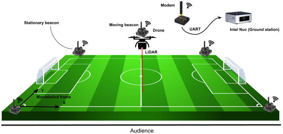
Marvelmind Robotics is a company that develops an off-the-shelf indoor GPS. Indoor localization is achieved with the use of ultrasound beacons. In this application, four stationary beacons are placed at a height of around 1 meter at all each corner of the robocup field. A fifth beacon is attached to the drone and connected to the drone's on-board power circuit. This beacon is known as the hedgehog or hedge for short. The hedgehog is a mobile beacon whose position is tracked by the stationary beacons. Pose data of the four beacons and the hedgehog are communicated using the modem, which also provides data output via UART. In this application, the pose data for the hedgehog is accessed through the modem using a C program. This program accesses the data via UART, decrypts the pose data and broadcasts it to the MATLAB/Simulink file via UDP. All of this is executed on the Intel Nuc. The co-ordinates derived from the Marvelmind setup was mapped to the NED co-ordinate frame used by the Pixhawk.
Autonomous Flight
This section explains how the on-board Pixhawk was used to fly the drone autonomously.
The actions taken by the Pixhawk are dictated by the messages it receives through the Mavlink message protocol [3]. The Mavlink messages were generated in Matlab Simlink running on an off-board Intel NUC computer and were communicated to the Pixhawk via telemetry. The telemetry connection was established through connecting two telemetry modules, one to the telem2 port of the Pixhawk and the other to the Intel NUC computer via USB. One Mavlink message is sent and another is received in every iteration of the Matlab Simulink simulation. Each Mavlink message sent to the Pixhawk include the position estimations taken from the Marvelmind setup and a required set point. The set point represents the target location that the Pixhawk, and subsequently the drone, is required to move to. The Mavlink message received include information regarding the drone's current pose and positions. This information was received to be used in planning the drone's path by deciding upon the set points.
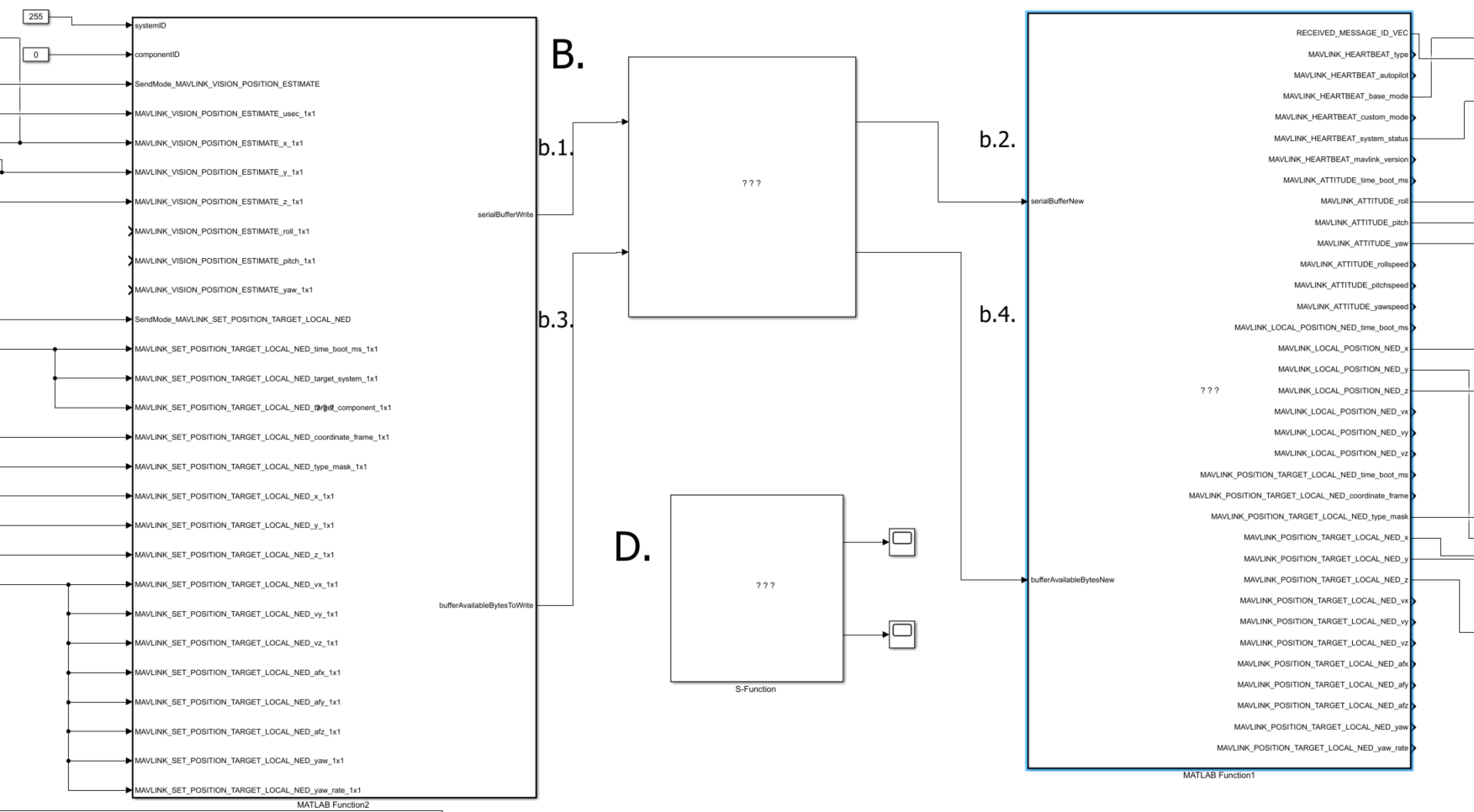
Pixhawk controllers by design has to be connected to a remote controller. As a result, a radio signal receiver was connected to the Pixhawk which received signals from a paired remote controller. The remote controller was used for the drone's take-off. When the drone reached an appropriate height, the remote controller was used to switch the Pixhawk to Offboard mode. The Offboard mode is the Pixhawk mode where it uses the set points received to move autonomously.
Note: To set up the Pixhawk to accommodate switching to Offboard mode, the parameters below has to be set as follows:
- SYS_COMPANION = 57600: Companion Link (57600 baud, 8N1)
- RC_MAP_OFFB_SW = 5 (Can be selected to be any other desired channel)
Path Planning
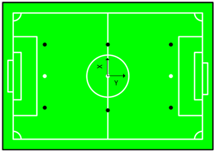
Path planning has a significant importance for autonomous systems. This lets a system like drone to find an optimal path. An optimal path can be defined as a path that has a minimal the amount of turning or hovering or whatever a specific application requires. Path planning requires a map of the environment and the drone needs to have its location with respect to the map. In this project, the drone is assumed to fly to the center of the pitch in manual mode and, after that, it switches to the automatic mode. In the automatic mode, a number of other assumptions are considered. We will assume for now that the drone is able to localize itself in regards to the map which is a RoboSoccer football field. A view of the match field is depicted in Figure below. The drone is assumed to stay with the same attitude during the game and it receives ball location on the map, x and y. Also, the ball is assumed to be on the ground. Another assumption is that there is no obstacle for the drone in its height. Finally, the position obtained from vision algorithms includes the minimum noise.
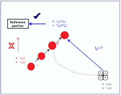
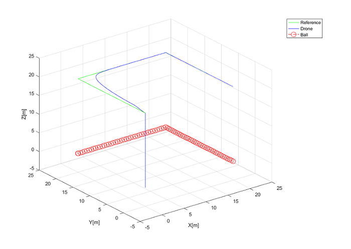
Based on these assumptions, the problem is simplified to find a 2D path planning algorithm. Simple 2D path planning algorithms are not able to deal with complex 3D environments, where there are quite a lot of structures constraints and uncertainties. Basically, the path planning problem is defined as finding the shortest path for the drone because of the energy constraint forced by hardware and the duration of the match. The drone that it is used in this project is limited to the maximum velocity of 3m/s. Another constraint is to have the ball in the view of the camera which is attached to the drone. The path planning algorithm receives x and y coordinates of the ball from vision algorithm, a reference path should be defined for the drone. One possible solution is to directly give the ball position as a reference. Since the ball mostly moves into different direction during the game, it is more efficient to use ball velocity to predict future position. In this manner, the drone would make less effort to follow the ball. Figure below illustrates how the drone traversed path is reduced by future position on the ball.
Using this approach, the result of the generated trajectory and drone position are shown in Figure below.
The drone should still put a considerable effort into tracking the ball constantly. Furthermore, results from the simulated game show that following the ball requires having a fast moving drone which may affect the quality of images. Therefore, the total velocity of the drone along the x and y-axes is limited for the sake of image quality. The video of the simulated game when a drone is following a ball is shown in video 1.
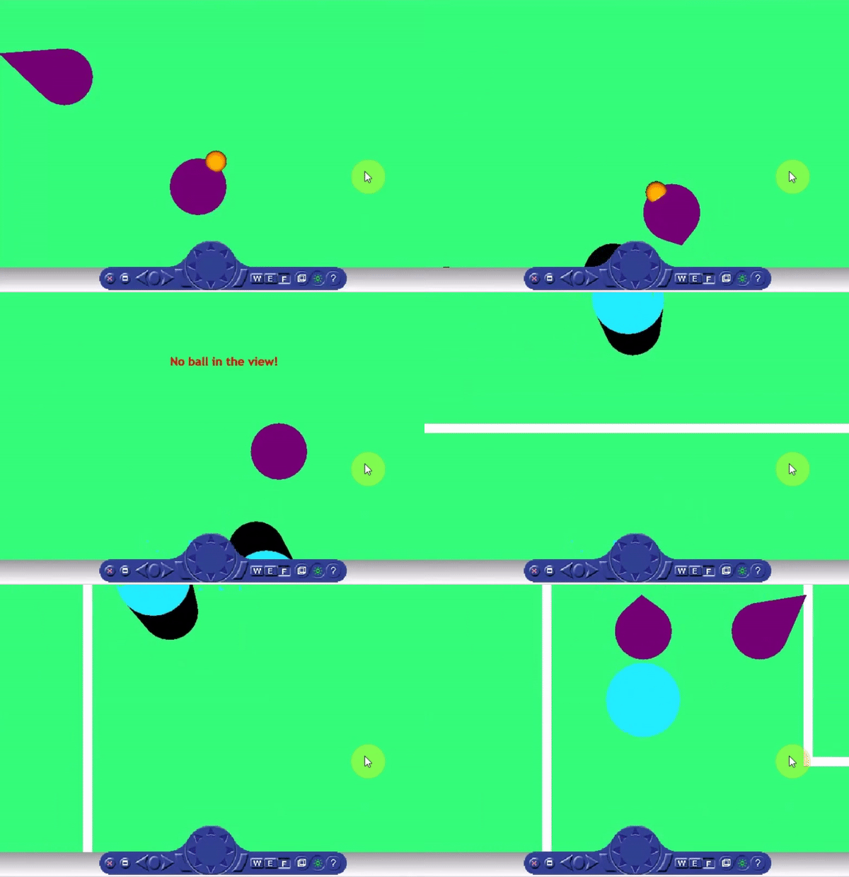
To make it more efficient, it is possible to consider a circle around the ball as its vicinity. When it is in the vicinity, supervisory control can change the drone mode to the position-hold. As soon as the ball moves to a position where the drone is out of its vicinity, it will switch to the ball tracking mode. On the other hand, the ball position in the images is sometimes occluded by the robot players. Thus, three different modes are designed in the current path planning. The first mode is ball tracking mode in which ball is far from the drone. The second one is position hold when the drone is in the ball vicinity. The Third one is occlusion mode in which drone moves around the last given position of the ball. However, this algorithm adds complexity to the system and may be hard to implement. A different scenario is to follow the ball from one side of the field by following the ball along y-axes. It is shown in the Video 2. In this case, the drone should be at a height more than what it can be in reality. Therefore, it is not practical.
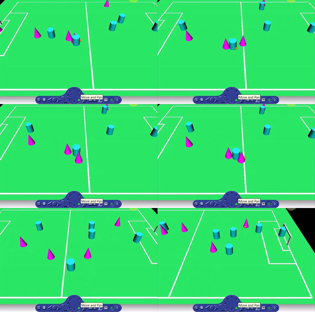
The drone follows the ball along the x-axes but it does not follow the ball completely along the y-axes. In fact, It moves in one side of the field and the camera records the image with an angle ( see equation 1).

A result of utilizing this approach is that the drone moves I a part of the field and it is not required to move all around the field to follow the ball. The coefficient in the equation one should be set based on camera properties and also the height in which the drone flies. Video 3 is provided to illustrate this approach.
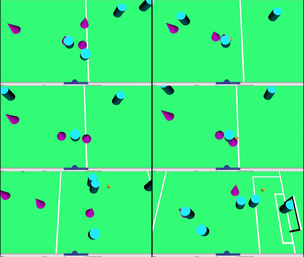
Event Detection and Rule Enforcement
In a robot soccer, referee has to correctly interpret every situation, a wrong interpretation can have a large effect in the game result. The main duty of a robot referee should be the analysis of the game, and the real-time refereeing decision making. A robot referee should be able to follow the game, i.e. to be near the most important game actions, as human referees do. In addition it should be able to communicate its decisions to the human referee. Thus, a camera is attached to the drone to capture images of the game and to stream the video to the HMI for the referee. Also the images have to be processed to estimate the position of the ball in the pitch.
Drone Camera
Compared to the field of vision that birds have, regular cameras have a rather narrow field of view, with an angle of around 70. The view angle of a fisheye camera is 180 degree, so it can cover a wider field of view than a normal camera. In addition, experimental conclusions in the Autonomous Referee System shows that it is difficult to track a fast moving ball with a narrow angle down-facing camera. In order to solve this problem, in this work, a fish-eye camera is selected. An effect of a wide field of vision might be that the ball can be tracked for a larger period of time without actively having to control the drone.Technical specifications of the fish-eye camera are in the following table.
| Camera | ELP-USB8MP02G-L180 |
|---|---|
| Sensor | Sony (1 / 3.2 ") IMX179 |
| Lens | 180 deg Fish-Eye |
| Format | MJPEG / YUY2 / |
| USB Protocol | USB2.0 HS / FS |
| Performance | 3264X2448 MJPEG 15fps YUY2 2fps
2592X1944 MJPEG 15fps YUY2 3fps 2048X1536 MJPEG 15fps YUY2 3fps 1600X1200 MJPEG 10fps YUY2 10fps 1280X960 MJPEG15fps YUY2 10fps 1024X768 MJPEG 30fps YUY2 10fps 800X600 MJPEG 30fps YUY2 30fps 640X480 MJPEG 30fps YUY2 30fp |
| Mass | 12 gram |
| Power | DC 5V 150mA |
Image Processing
Objectives
The position of the ball in the pitch have to be estimated. Therefore, images have to be captured from the camera (attached to the drone) and processed to detect the ball and estimate its position. Using the position of the ball, a recommendation have to be sent to the supervisory control when the ball goes out of pitch (B.O.O.P). Also, referee needs a video streaming of the game to be able to follow the game. As a result, video streaming of camera have to be sent to the HMI for the remote referee.
Method
Two methods are available for detecting a ball in the image:
- MATLAB
- ffmpeg
- gigecam
- hebicam
- C++/python/Java
- OpenCV
Test results from the ‘MSD Group 2016’ shows that capturing one image in MATLAB takes 2.2 seconds. This can be very slow for ball detection and position estimation of the ball, [Autonomous Referee System, 2016]. Therefore, it would be better to use C++ instead of MATLAB. To this end, C++/OpenCV library has used in this project and the position of the ball can be estimated based on its color (yellow/orange/red).
Transformation
After finding position of the ball in the image, a mathematical model is needed to describe how 2D Pixel points get projected into 3D World points. This mathematical coordinates are shown in the following Figure:
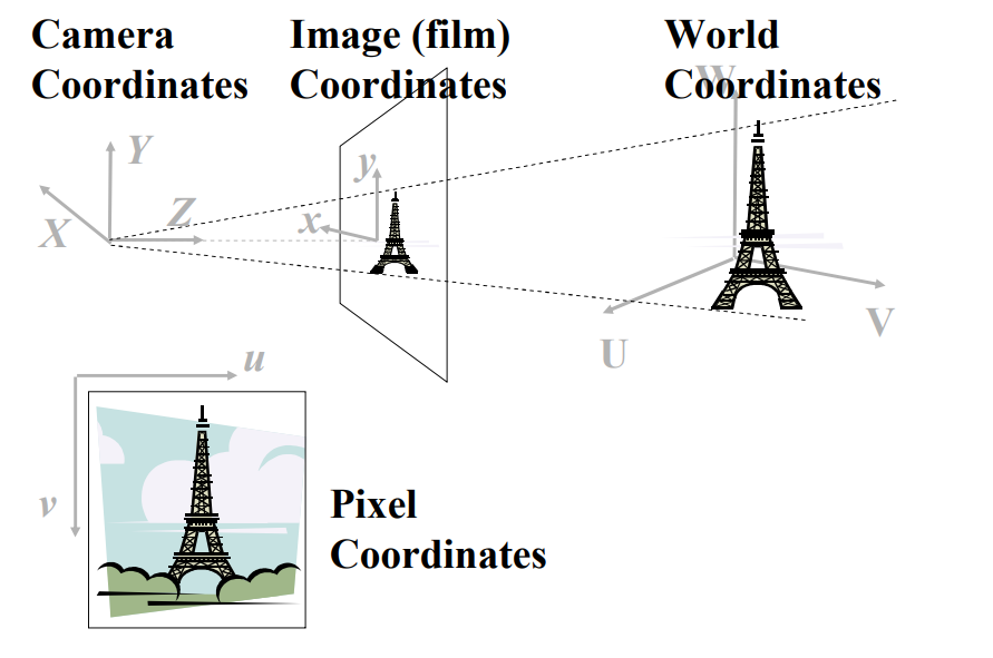
Therefore, the concern is to drive the backward projection as follows:

The process of image formation, in a camera, involves a projection of the 3-dimensional world onto a 2-dimensional surface. The depth information is lost and we can no longer tell from the image whether it is of a large object in the distance or a smaller closer object. Firstly, for projection from pixel coordinate to Film coordinate an undistorted image is required. To undistort the image, OpenCV library can be used. In order to apply it “calibration matrix” and “distortion coefficients” are needed which can be obtained from camera calibration code using ARUCO markers. For more information see OpenCV: Fisheye camera model. Using this coefficients and basic perspective projection, position of the ball with respect to film coordinate can be achieved. Secondly, projection from film coordinate to camera coordinate is illustrated in the following Figure:
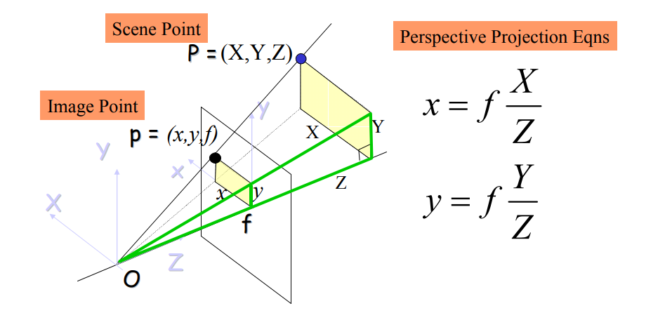
Finally, after applying projection equation and finding the position of the ball with respect to the camera, a rigid transformation (rotation+ translation) between world and camera coordinate systems is needed.
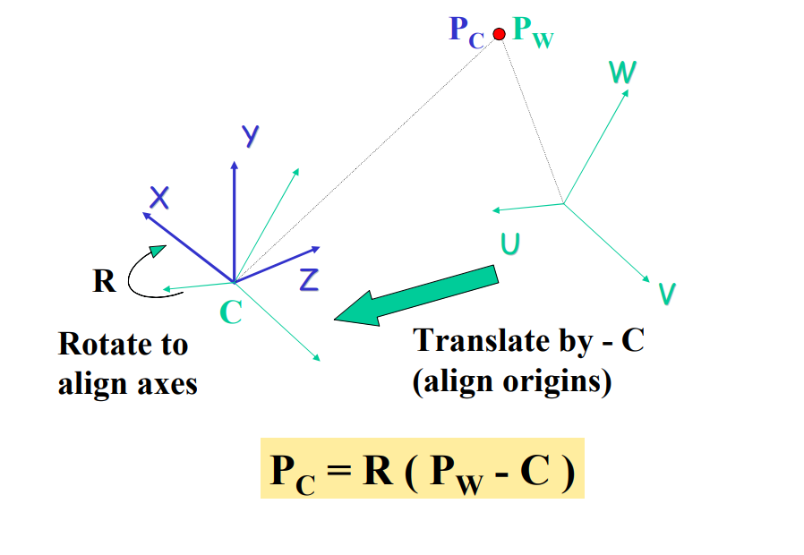
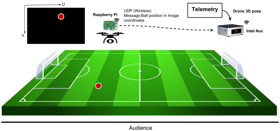
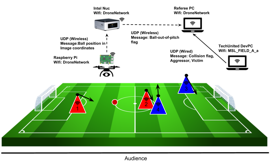
Here, the position of the drone in the world model is available from top camera. Thus, there is no need to calculate camera transformation to world model. Position of the ball with respect to the camera is calculated on the raspberry pi attached to the drone and this data is sent via UDP to the NUC. On NUC using this position and position of the drone, position of the ball in the world model can be calculated. The connections between drone and ground station is shown here:
Detecting Ball Out of the Pitch
The objective is to detect the ball out of the pitch and send this data to the remote referee. The idea is to detect ball out of the pitch based on the position of the ball and the boundaries of the pitch. It is recommended to use this data with combination of line detection in the algorithm for more accuracy.
Collision Detection
Collisions between robots can be detected by the distance between them and the speeds the robots are traveling at. The collision detection algorithm assumes prior knowledge of the positions of each player robot. In this project, two methods of tracking the robot position were studied and trialed - ArUco Markers, and the use of TechUnited's world model.
ArUco Markers
ArUco is a library for augmented reality (AR) applications based on OpenCV. In implementation, this library produces a dictionary of uniquely numbered AR tags that can be printed and stuck to any surface. With sufficient number of tags, the library is then able to determine the 3D position of the camera that is viewing these tags, assuming that the positions of the tags are known. In this application, the ArUco tags were stuck on top of each player robot and the camera was attached on the drone. The ArUco algorithm was reversed using perspective projections to determine the position of the AR tags using the known position of the drone (localization). However, two drawbacks of this solution were realized.
- The strategy for trajectory planning is to have the ball visible at all times. Since the priority is given to the ball, it is not necessary that all robot players are visible to the camera at all times. In certain circumstances, it is also possible that a collision occurs away from the ball and hence away from the camera’s field of view.
- In this application, the drone and the robot players will be moving at all times. At high relative speeds, the camera is unable to detect the AR tags or detects them with high latency. During trials, it was also observed that the field of view of the fish-eye camera to track these AR tags is heavily limited.
Due to these drawbacks, and considering that the drone referee will be showcased using the TechUnited robots, it was decided to use TechUnited’s infrastructure to track the player robots.
TechUnited World Model
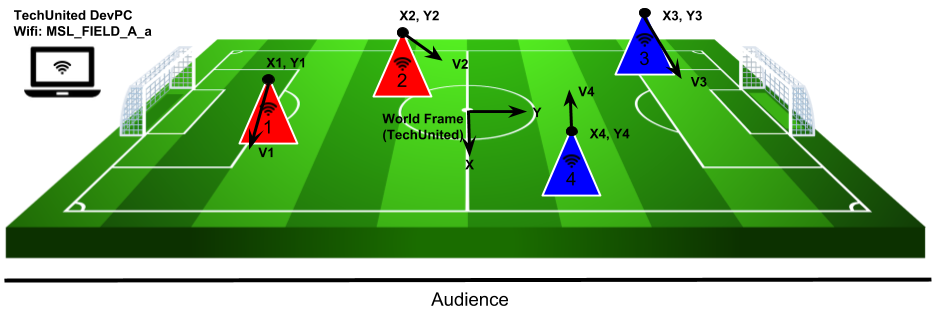
The TechUnited robots, also known as Turtles, continuously broadcast their states to the TechUnited network. In the robotics field of TU Eindhoven, this server is a wireless network named MSL_FIELD_A_a. The broadcasted states are stored in the TechUnited World Model, which can be accessed through their multicast server. In this application, the following states are used for the collision detection method:
- Pose (x, y, heading)
- Velocity (in x direction, in y direction)
The image below shows 4 player robots divided into two teams. Using the multicast server, the position and velocity (with direction) is measured and stored. The axes in the center is the global world frame convention followed by TechUnited.
Collision Detection
Once robot positions are known, collisions between them can be detected using a function of two variables,
- Distance between the robots
- Relative velocity between the robots
These variables can be measured using the positions of the robots, their headings and their velocities. The algorithm to detect collisions uses the following pseudo-code.
while(1){
  for(int i=0; i<total_players; i++){
    store_state_values(i);
  }
  for(int reference=0; reference<total_players; reference++){
    for(int target=j; target<total_players; target++){
      distance_check(reference, target);
      if(dist_flag == 1){
        velocity_check(reference, target);
        determine_guilty_player(target, reference, vel_flag);
      }
    }
  }
}
In the above pseudo-code, collisions are detected only if two robots are within a certain distance of each other. In this case, the relative velocity between these robots are checked. If this velocity is above a certain threshold, a collision is detected. The diagram below describes the scenario for a collision. In this diagram, the red line describes the two robots being close to each other, within the distance threshold. It can be considered that the robots are touching at this point. However, a collision is only defined if these robots are actually colliding. So, the relative velocity, described as rel_v' in the diagram, is checked.

The above pseudo-code is broken down and explained below:
for(int i=0; i<total_players; i++){ //check over all playing robots
  store_state_values(i);
}
Store State Values: The for loop runs over all playing robots. The number of playing robots are checked before entering the while loop, in this application. The store_state_values function stores the state values of each robot into a player_state matrix. The state values stored are the pose (x, y, heading) and the velocities (vel_x, vel_y).
for(int reference=0; reference<total_players; reference++){
  for(int target=reference; target<total_players; target++){
    distance_check(reference, target);
    ...
  }
}
Distance Check: For this application, a n x n matrix is made, where n describes the total number of players. The rows of this matrix describes the reference robot and the columns describe the target. In the code snippet above, two for loops can be seen. However, the second for loop starts from the reference player number. This is done to reduce redundancies and restrict the number of computations. This can be seen in the matrix description below. Every element with an x is redundant or irrelevant.
_|1|2|3|4|
1|x|0|0|0|
2|x|x|0|0|
3|x|x|x|0|
4|x|x|x|x|
So, for 4 playing robots (16 interactions), only 6 interactions are checked: 1-2, 1-3, 1-4, 2-3, 2-4, 3-4. The remaining elements in the matrix are redundant. The distance_check function checks if any two robots are within colliding distance of each other (only the above 6 interactions are checked). In this application, the colliding distance was chosen to be 50 cm. If the distance between robots is less than 50cm, the corresponding element in the above matrix is set to 1.
if(dist_flag == 1){
  velocity_check(reference, target);
  determine_guilty_player(target, reference, vel_flag);
}
Velocity Check: This function is called only if the distance flag is set to 1, when two robots are touching each other (distance between the robots < 50cm). Using the individual velocities and headings of each touching robot, a relative velocity is calculated at the reference robot as origin. If the absolute value of this relative velocity is greater than 5 m/s (velocity threshold in this application), the velocity flag is set. This flag, however, is a signed value, i.e. it is either +1 or -1 depending upon the direction of this relative velocity.
Determine Guilty Player: The sign of the velocity flag tells us which robot is guilty of causing this collision. If the flag is positive, the reference robot is the aggressor and the target robot is the victim of the collision. For a negative flag value, it is the other way around. This determination is important to assign blame and award free-kicks/penalties by the referee during the match.
Interfaces
Developing additional interfaces for event detection and rule enforcement was necessary due to the following constraints.
- Intel Nuc was unreliable on-board the drone. While the telemetry module and the Pixhawk helped fly the drone, a Raspberry Pi was used for the computer vision. This Raspberry Pi communicates over UDP to the Nuc. Both the Nuc and the Raspberry Pi operate over the DroneNetwork wireless network.
- The collision detection utilizes the World Model of the TechUnited robots. To access this, the computer must be connected to the TechUnited wireless network. It was realized that the collision detection algorithm has nothing to do with the flight of the drone, and hence it is not necessary to broadcast the collision detection information to the Intel Nuc. Hence, this information was broadcasted directly to the remote referee over the TechUnited network.
The diagram below describes all these interfaces and the data that is being transmitted/received.
Human-Machine Interface
The HMI implementation consists of 2 parts.
- A supervisor, which reads the collision detection and ball-out-of-pitch flag and determines the signals to be sent to the referee.
- A GUI, where the referee is able to make decisions based on the detected events and also display these decisions/enforcements to the audience.
Supervisory Control
The tasks performed by the supervisor were confined to rule enforcement. These tasks are explained below.
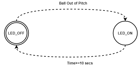
- The supervisor receives input from the vision algorithm as soon as event Ball Out of Pitch occurs. Afterwards, it provides a recommendation to the remote referee via a GUI platform running on his laptop. A constraint has been applied to terminate the recommendation automatically after 10 seconds if the referee doesn’t acknowledge the recommendation.
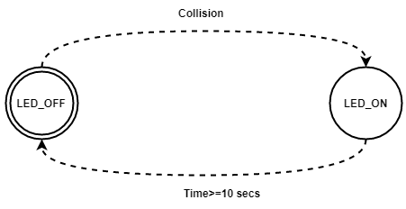
- The supervisor receives input about the occurrence of the event Collision Detected. As soon as this event is detected, a recommendation is sent to remote referee via GUI Platform. The termination strategy is same as the previous event termination.
- The referee has a button to show the audience the decision he has taken. For this, as soon as he pushes the button in GUI the decision is send to other screen as an LED and the supervisor terminates the LED after certain time as it releases the push button automatically.
The following automatons were used for these tasks.
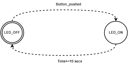
A brief study of both the Matlab state flow and CIF was conducted to decide which platform to be used to design the supervisor. Afterwards, we concluded that it is better to use CIF tool in our case because of the following reasons:
- In CIF it is easy to synthesize a supervisory controller as soon as we create the model of the system.
- In CIF one can straight forwardly check about controllable, uncontrollable states as well as marked and unmarked states.
- In CIF the defining of states and also specifying what kind of states is quite easy.
- In CIF the complexity to design the supervisory is lesser than State-flow.
- It is quite simple to implement the supervisor constructed in CIF in MATLAB.
To implement CIF code in Simulink a Matlab Simulink S-Function C-Code was generated, this code was further used in Simulink using S-function block. For code generation steps given in CIF website [4] is used.
Graphical User Interface
The background
The acceptance of model-based design across the embedded community has led to more and more systems being developed in Simulink. The complexities of Simulink models are increasing with more and more features being incorporated into controllers. To analyze the outputs of Simulink models we generally rely on scope and display blocks. But, when we work with large models, it is no longer possible to understand what is happening in the system with scope and display block alone. It can be better if you have a customizable HMI which consists of a panel of buttons, checkboxes et cetera which feeds all the necessary data required to the model and there is a similar Graphical User Interface(GUI,also known as UIs) which displays the output of the model use plots, fields et cetera.
In this project, two agents will be used to referee the game: a drone moving above the pitch and a remote human referee, receiving video streams from a camera attached to the drone. A camera attached to the UAV help providing video streams allowing for an adequate situational awareness of the human referee, and consequently enabling him/her to make proper decisions. In addition, the vision-based algorithm was developed for providing recommendations such as “Ball Out Of Pitch” and “Collision Of Two Robots” to help human referee for making the final decision. It is worth mentioning that UAV only provide the RECOMMENDATION and FINAL decision will be made by the human referee. Therefore, a visualization and command interface shall allow interaction between the drone and the human referees. In particular, besides allowing the visualization of the real-time video stream, this interface shall allow for more features such as on-demand recommendation (“Ball Out Of Pitch” and “Collision Of Two Robots”) and enable the human referee to send decisions (kick-off, foul, free throw, etc.) which should be signaled to the audience via LEDs place on the second ground station interface.
Hence, this documentation provides detail information on the process in which HMI is built. HMI used in this study was created with help of MATLAB-GUIDE. GUIs provide point-and-click control of software applications on the unmanned aerial vehicle (UAV) in this study case. GUIDE (GUI development environment) provides tools to design user interfaces for custom apps. Using the GUIDE Layout Editor, UI graphical design can be changed. GUIDE then automatically generates the MATLAB code for constructing the UI, which you can modify to program the behavior of your app.
Consequently, the final design of HMI should cover following points:
- Two GUI’s should be implemented ( one for the human referee and one for the audience)
- Timer (countdown of the game)
- Start/Stop of application (Simulink in this case) remotely
- Initialization/Termination of the game
- Provide abovementioned recommendation when it is requested
- Real-time video stream
- Communication with audience interface (ability to share the result with the audience)
Literature review
For basic of MATLAB-GUIDE, the interested reader is referred to:
- The online course on www.udemy.com under name of “MATLAB App Designing: The Ultimate Guide for MATLAB Apps”
- buildgui.pdf
- GUI Example
- Gui_tutorial.pdf
- Use Matlab GUI with Simulink models
Among different functions available in the Simulink/GUIDE, knowing of the following functions is suggested to the reader as they may come handy at times. The functions can be named as follows: Among different functions available in the Simulink/GUIDE, knowing of the following functions is suggested to the reader as they may come handy at times. The functions can be named as follows:
*  open_system(‘sys’)
*  close_system(‘sys’)
*  paramValue = get_param(object, paramName)
*  set_param(object, paramName, Value)
AIM
To make 2 GUI's
- Remote Referee interface (1st GUI)
- Collects information from Simulink model and process it for a human referee
- Control the Simulink model remotely
- Audience interface (2nd GUI)
- Controlled by 1st GUI in order to change the LED colors depends on referee decision
Two GUI’s have been designed to fulfill the requirement. This is done by drag and drop work using GUIDE. These two GUI’s could be seen in Figure 1 and 2 respectively.
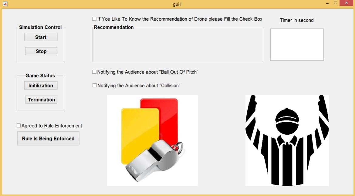
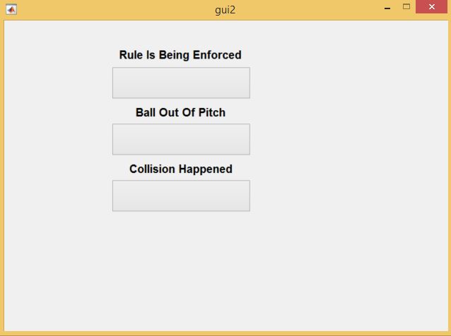
Property Inspector of GUI’s
The following settings should be set in Property Manager prior to proceeding any further
- All components were given specific Tags for easy identification
- Hand Visibility of both GUI’s were set to “ON” for data flow between both GUI’s
- String of Edit Text was deleted (place where Timer is going to work)
Opening Function (OpeningFcn)
In addition, following commands were implemented in Opening Function part of 1st GUI:
set(handles.gameover,'visible','off');
set(handles.BOOP,'visible','off');
set(handles.collision,'visible','off');
In 1st GUI OpeningFcn, following code implemented to automate loading and opening of Simulink file
find_system('Name','check');
open_system('check');
In 1st GUI OpeningFcn, the background images of axes were introduced
bg = imread('C:\Users\20176896\surfdrive\HMI Drone\HMI\ref4.jpg');
axes(handles.axes1)
imshow(bg);

bg1 = imread('C:\Users\20176896\surfdrive\HMI Drone\HMI\ref2.png');
axes(handles.axes2)
imshow(bg1);
Provide Recommendation (Receiving/Setting Data from/to Simulink)
It was mentioned earlier that interface provided for the human remote referee should provide on-demand recommendation (“Ball Out Of Pitch” and “Collision Of Two Robots”) and enable the human referee to send decisions (kick-off, foul, free throw, etc.). Therefore, there is a need for the visualization and command interface designed for human referee to be able to receive real-time DYNAMIC data from supervisory, UDP or any type of communication which is running in Simulink. There are different methods for interaction with dynamic simulation. This article describes some of the ways in which you can utilize Simulink’s data in MATLAB GUI. Simulink Function, Simulink Call back Functions, Simulink Event Listener, Custom MATLAB Code S-Function and Gluing the Simulink with GUIDE are some of the methods that can be used for this purposes. However, this documentation does not intend to explore every option in detail. To avoid future confusion, some of the experimented NON real-time methods for information collecting from Simulink model is explained as follow:
Non-real-time solutions
- Using To Workspace block to export the data.However, only data at the very beginning of the simulation can be extracted.
- Using Scope and change some properties: check Save Data To Workspace and Uncheck Limite data to Last. However, ScopeData would appear in workspace only once the simulation is stopped.
- Using the SIMSET function to define which workspace the Simulink model interacts with. ( simOut = sim(model,Name,Value) )
Real-time solution
For receiving data from Simulink in real-time, combination of RuntimeObject and Simulink Event Listener have been used. Interested reader is referred to the following link:
Access a Run-Time Object
Therefore, first load and start the simulation by following commands:
load_system('myModel')
set_param('myModel','SimulationCommand','Start');
Then, to read data on any line of your Simulink model:
- , Get a Simulink block object (let's try a Clock with the name Clock as an example):
block = 'myModel/Clock';
rto = get_param(block, 'RuntimeObject');
- Then get the data on its first (or any) output port (or input) of that block.
time = rto.OutputPort(1).Data;
It is worth mentioning that, the displayed obtained data may not be the true block output if the run-time object is not synchronized with the Simulink execution. Simulink only ensures the run-time object and Simulink execution are synchronized when the run-time object is used either within a Level-2 MATLAB S-function or in an event listener callback. When called from the MATLAB Command Window, the run-time object can return incorrect output data if other blocks in the model are allowed to share memory. To ensure the Data field contains the correct block output, open the Configuration Parameters dialog box, and then clear the Signal Storage Reuse check box
Simulink Event Listener (Listen for Method Execution Events)
One application for the block run-time API is to collect diagnostic data at key points during simulation, such as the value of block states before or after blocks compute their outputs or derivatives. The block run-time API provides an event-listener mechanism that facilitates such applications. To apply Event Listener to any Simulink Block, add_exec_event_listener (h = add_exec_event_listener(blk,event,listener)) can be used. This will allow you to registers a listener for a block method execution event. For doing so, in the Simulink model, double-clicking on the annotation below the Model Properties and implement the desired code in the StartFcn-Callback.
In Event Listener, blk is specifying the block whose method execution event the listener is intended to handle by defining full pathname of a block. Check is the name of the Simulink Model and S-Function is the block whose method execution event the listener is intended to handle. Afterward, type of Event which the listener listens should be specified base on need and application. Events may be any of the followings:

Then, the function displayBusdata.m (custom made function) is registered as an event listener that is executed after every call to the S-function's Outputs method. The calling syntax used in displayBusdata.m follows the standard needed for any listener. The function displayBusdata.m can be found in the source code.
In conclusion, in the GUI designed, the referee can have access to real-time data of supervisory (S-Function) in Simulink model when he/she is interested (can express this by filling the checkbox). Therefore, in call back of this check box, abovementioned functionality is incorporated.
Data Flow between two GUI’s
Based on the above-mentioned information, the remote referee final decision should be signaled to the audience via LEDs place on the second ground station interface. Therefore, there should be a data flow between the GUI provided to the human referee and the GUI which is provided for the audience. For data flow between two GUI’s, Hand Visibility of both GUI’s should be set to “ON”. No codes need to be implemented in the 2nd GUI (Audience GUI) and the color of LEDs (push buttons in audience GUI) can be changed within the first GUI (remote referee GUI) according to the commands which are implemented.
Timer Implementation
The remote referee can set and see the remaining time of the game at all times. The Timer (Count down) could be created performing following steps:
- Create a timer object.
- Specify which MATLAB commands you want executed to control the object behavior.
- Trigger the object using the Push Button. (here Initialization push button)
Real-Time Video Feed from USB Webcam
The live video stream can be incorporated in a custom graphical user interface (GUI) using the “preview” function in any Handle Graphics® image object if the USB camera is PHYSICALLY connected to the computer that GUI is running in. First, make sure that “MATLAB Support Package for USB Webcams” and “Image Acquisition Toolbox Support Package for OS Generic Video Interface” Hardware Support Packages are installed. Then, to use this capability, create an image object (i.e. AXES) and then call the preview function, specifying a handle to the image object as an argument. The preview function outputs the live video stream to the image object you specify. The following example calls the preview function, specifying a handle to the image object.
axes(handles.axes1);
vid=videoinput('winvideo',2);
himage=image(zeros(1024,768,3),'parent',handles.axes1);
preview(vid,himage);
For better understanding, the interested reader is referred to:
Start/Stop of Simulink remotely
The status of simulation can be changed with the following commands in call back of specified push bottom in GUI
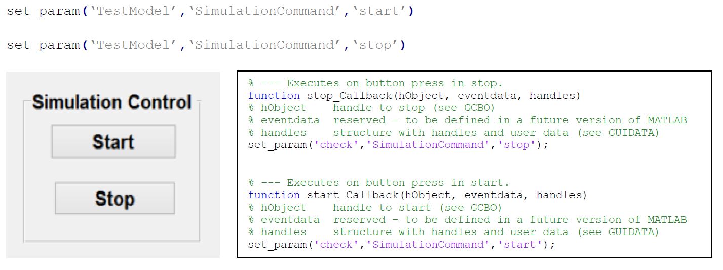
Further information could be found at the following link:
Initialization/Termination of the game
The initialization and termination of the game can be controlled remotely via GUI provided to the human referee. The remote referee should be able to terminate the game at ALL the time. For better understanding, the interested reader is referred to the "Initialization" and "Termination" parts of the source code.
Live Video feed and Replay
One of the important feature in the HMI was to provide the human referee with a live video stream of the game situation with a replay feature. An attempt which was made to achieve this which was quite successful in application, but due to lack of resources and time constraints implementation results were not up to the mark.
Implementation
During the implementation a mobile camera was converted to a IP-camera using a IP-Webcam android application. The IP-address of the camera is known VLC-media player can be used to create a Live video feed and record a video in the system simultaneously [5]. The IP of this IP camera can also be used in a Matlab script to create a screen for Live video feed. The recorded video can be used by referee as a reference to verify the events that happened in the game.
Integration
Demo Video
Risk Analysis
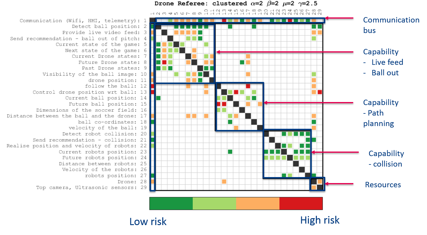
The goal of this exercise to analyze risk within the drone referee system based on the objective function called the technology risk (TR). Here, TR is the summation of ratings given to the actual test output and failure risk of elements within the system architecture. Figure shows the system architecture mapped onto a matrix, here the diagonal terms of the matrix represents the elements connected with themselves and off diagonal terms represent the interaction within the elements.
Each cell in the matrix corresponds to the multiplication of the TR values of the two interacting components. Moreover, by permuting the rows and columns of the matrix using a clustering algorithm the underlying structure of the system may be revealed. To this end a multilevel flow based Markov clustering has been used.
The clustering algorithm permutes the system with respect to capabilities, resources and a bus connection. Furthermore, the color map shows the increase in risk from green to red, this is highlighted in figure. The figure shows several risks within the system capabilities and the possible reasons for a risk in follow the ball has been summarized below.
During implementation of the drone referee we found out that the drone was unable to move to a predefined location because the marvelmind sensors were unable to give a yaw input to the drone. Moreover, the magnetometer within the pixhawk was also inoperable. Although the ideal solution here would have been to use the top camera for the yaw input but unfortunately the top camera code was not working. Hence, we recommend to fuse the data from the marvelmind and the top camera to localize the drone and follow the ball.
Conclusions and Recommendations
Conclusions
- The old arrangement of having an on-board Intel NUC computer has be replaced with a raspberry pi and a telemetry connection.
- Ball detection and ball out of pitch has been successfully implemented using a manually operated drone.
- Collision Detection
- Detection and Tracking of robots using the drone camera was proven to be unreliable due to drone/robot speed and processing latency issues
- It was decided to access state values from the robots themselves
- The TechUnited world model was accessed and used successfully
- Using the robots' positions and velocities was proven to be reliable, considering the communication interfaces to be working perfectly
- Communication Interfaces
- The telemetry interface demonstrated latency issues and had a significantly lower update rate than with the Pixhawk connected directly to the on-board Nuc
- The UDP interfaces showed high update rates and reliability. These connections, however, were not completely secure
- There was high latency in the video streaming of the fish-eye camera using the Raspberry Pi. This was solved by using an IP camera. This proved to be reliable as a stand-alone solution, however, it wasn't integrated with the final system
- Simulation conducted to gain insights related to path planning.
- Supervisory Control
- It was found that CIF is a better tool when compared to Matlab state flow for designing a supervisor for the current use case. A supervisor made in CIF tool was successfully implemented in Matlab simulink by converting it into Matlab S-function C-code.
- HMI has been established for the remote referee.
- Communication between the human remote referee interface and audience interface has been established
Recommendations
- Fuse sensor data of top camera and indoor GPS system for drone localization.
- To have a more compact drone because the current drones propellers airflow displaces the ball.
- Collision Detection
- Consider using either beacons on-board the robot players or the top cam for robot detection and tracking. This eliminates the dependency on the TechUnited software architecture
- As an alternative to the above, consider developing a standardized interface for robo-soccer teams to provide robot states (position/velocity/acceleration) to the referee system
- The collision detection algorithm needs to be updated with consideration towards the impact on the robots, to determine the player guilty of causing the collision
- Consider predictive algorithms that can predict an impending collision
- Detect the position of the collision and integrate this information with the trajectory planning to re-orient the drone during collisions
- Consider prediction based algorithms for collision detection.
- Use a vision algorithm or tracking sensor on the players to determine their position.
- Combine line detection algorithm with the current algorithm for improving the accuracy.
- Procure a FPV camera kit or a wide angle IP camera so that the range of vision is better than a mobile phone camera. It has been realized that IP camera is a feasible solution for providing Live feed and Replays, also Matlab has compatible hardware package to support it.
Additional Resources
The developed software is divided into two categories:
- C/C++ Code
- MATLAB/Simulink Code
The C/C++ codes are open-source on Github here and the team's private Gitlab repository here. For access to the Gitlab workspace, please write an email to Aditya Kamath (a.kamath@tue.nl). The Gitlab/Github repository contains the following source code:
- ArUco detection/tracking: This is a re-used code sample using the aruco library for the detection and tracking of AR markers
- UDP interfaces: This repository contains sample code for local/remote UDP servers and clients
- TechUnited World Model: The repositories multicast and Global_par are used to access the TechUnited world model and also contains the code developed for collision detection
- Ball detection/tracking: This contains the code for the detection of a red colored ball
- Marvelmind: This code reads pose data of a selected beacon from the MarvelMind modem and broadcasts data via UDP. This is accessed by the MATLAB/Simulink files.
The MATLAB/Simulink files are stored here and contain the following resources:
- MAV004: This repository contains all the files required to communicate and control the pixhawk using MATLAB/Simulink
- HMI and Supervisory Controller: This contains an integration of the developed supervisor and referee/audience GUI
- DSM: This folder contains files for the risk analysis matrix
- Drone Motion: This repository contains simulation files for trajectory planning