PRE2017 3 Group 17 Test Cases: Difference between revisions
m left align picture |
|||
| Line 8: | Line 8: | ||
Test 1 is simple test to check the basics of loading in an environment and nodes.<br> | Test 1 is simple test to check the basics of loading in an environment and nodes.<br> | ||
[[File:Test1.jpg]] | [[File:Test1.jpg|thumb|left|upright=0.35|alt=Test1.]] | ||
The test below was created to test an edge-case scenario, where the end node is not reachable. This test also illustrates very well that it is not desired that the drone simply flies back. In this case it is usefull if the nearest node would become the target. How does the drone choose these target nodes, or does the user need to pick a reachable target node for the system.<br> | The test below was created to test an edge-case scenario, where the end node is not reachable. This test also illustrates very well that it is not desired that the drone simply flies back. In this case it is usefull if the nearest node would become the target. How does the drone choose these target nodes, or does the user need to pick a reachable target node for the system.<br> | ||
[[File:Test2.jpg]]<br><br> | [[File:Test2.jpg]]<br><br> | ||
Revision as of 10:08, 19 March 2018
Layout with nodes
Below a couple of very basic initial test layouts can be found. These layouts are used to test the parser, the model and the UI.
Circles (or Nodes) represent the junctions in a building.
Solid Circles (or solid Nodes) represent the beginning and end junction of the drone path.
Solid lines between junctions (or Edges) represent the paths between junctions on the same floor.
Dashed lines between junctions (or dashed Edges) represent paths between junctions on a different floor. For instance, an elevator shaft or staircase.
Other solid lines represent walls. In the case that an edge passes a wall, there is an opening in that wall with sufficient space for a drone to fly through. For instance, a door or large window.
Test 1 is simple test to check the basics of loading in an environment and nodes.
The test below was created to test an edge-case scenario, where the end node is not reachable. This test also illustrates very well that it is not desired that the drone simply flies back. In this case it is usefull if the nearest node would become the target. How does the drone choose these target nodes, or does the user need to pick a reachable target node for the system.

A simple test to see if the optimal path was chosen.

Another test to see if the optimal path was chosen.
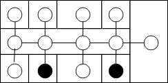
A test to see if boundaries are respected. However, since the drones follow the nodes this test case has less relevance.
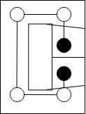
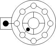
A circular test case. Also a boundary case, depending on your implementation of an algorithm can get stuck on searching for the optimal path, since there are always combinations that cannot be scouted.
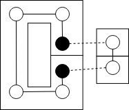
A very besic test case to make us think about difference in floors and how this will be implemented.
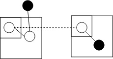
Also a test case with mulitple floors, however, this time there are multiple paths:
- Stays on the same level, but has more nodes
- Different level, but with less nodes
This test case is made to make us think about how we want to handle different floors. Do we always require the absolute shortest flight path, or do we take energy into account? (since lifting a heavy object requires more force than keeping it on the same level
