Embedded Motion Control 2017 Group 9: Difference between revisions
| Line 130: | Line 130: | ||
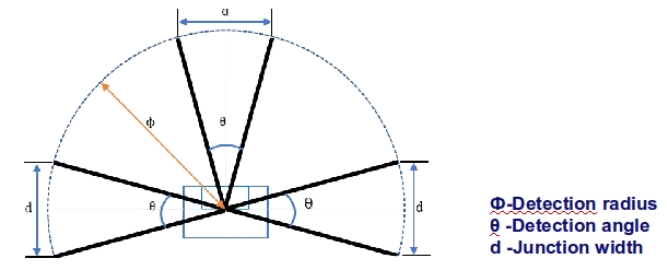
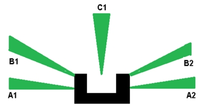
In the following picture, it is clear that three laser bundles in forward, minus ninety degree and plus ninety degree are selected to detect the junction. In order to find junction in perfect way, the detection radius and detection angle need to be well calculated. | In the following picture, it is clear that three laser bundles in forward, minus ninety degree and plus ninety degree are selected to detect the junction. In order to find junction in perfect way, the detection radius and detection angle need to be well calculated. | ||
[[File:Example.jpg]] | |||
<math>Insert</math> | <math>Insert formula here</math> | ||
These two equations will make sure the pico can find junction in thw widthest corridor and also could go through the junction in open loop. Finally, the detection radius is set to be 0.85. | These two equations will make sure the pico can find junction in thw widthest corridor and also could go through the junction in open loop. Finally, the detection radius is set to be 0.85. | ||
Revision as of 19:10, 14 June 2017
Group Members
| Name: | Student id: |
| Mian Wei | X |
| Zhihao Wu | X |
| Petrus Teguh Handoko | X |
| Bo Deng | X |
| Bo Cong | X |
| Jian Wen Kok | X |
| Nico Huebel | Tutor |
Initial Design
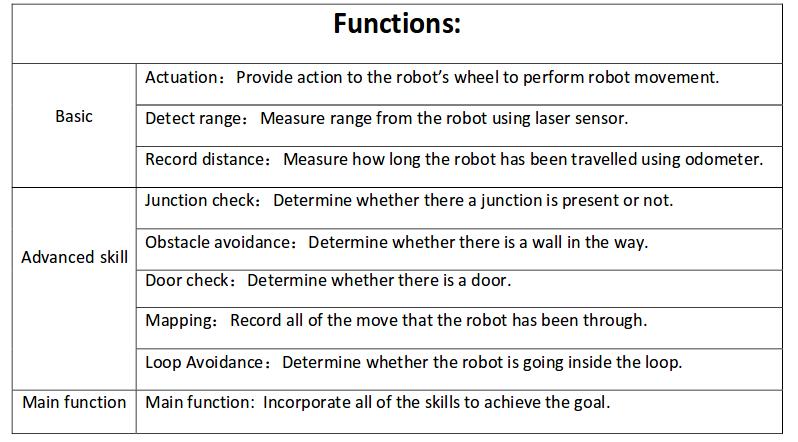
The initial design for the maze challenge is elaborated below. It includes the requirements, functions, components, schematic of program structure, specifications and interfaces to define the working of PICO. The file for the initial design is included here: File:Assignment-for-week1.pdf
Requirements
➢ PICO drives autonomously through maze
➢ Being able to take a turn without touching a wall
➢ Being able to detect a turn or branching corridors
➢ Avoiding collisions with obstacles (including the walls)
➢ Driving straight and rotating smoothly
➢ PICO should not stand still for 30 seconds
➢ Avoid getting trapped in a loop of the maze
➢ Being able to recognize the door
Functions
Components
drive control
‐Holonomic base (omni‐wheels)
‐Pan‐tilt unit for head
detection
‐170◦ wide‐angle camer
‐Laser Range Finder (LRF)
‐Wheel encoders (odometry)
‐Asus Xtion Depth sensor
world model
computer
‐Intel I7
‐Ubuntu 14.04
Specifications
- maximum translational speed of 0.5 m/s
‐ maximum rotational speed of 1.2 rad/s
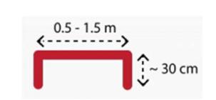
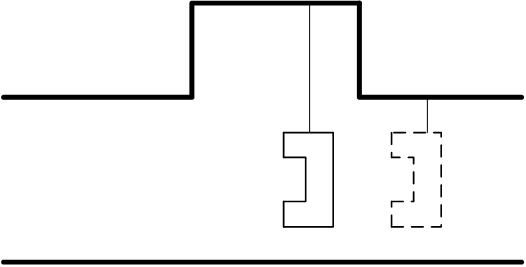
‐ Door template: length of 0.5 ‐ 1.5m and with side walls of approximately 30cm, see figure below
‐ LRF accuracy and range unknown
‐ odometer accuracy unknown
Interfaces
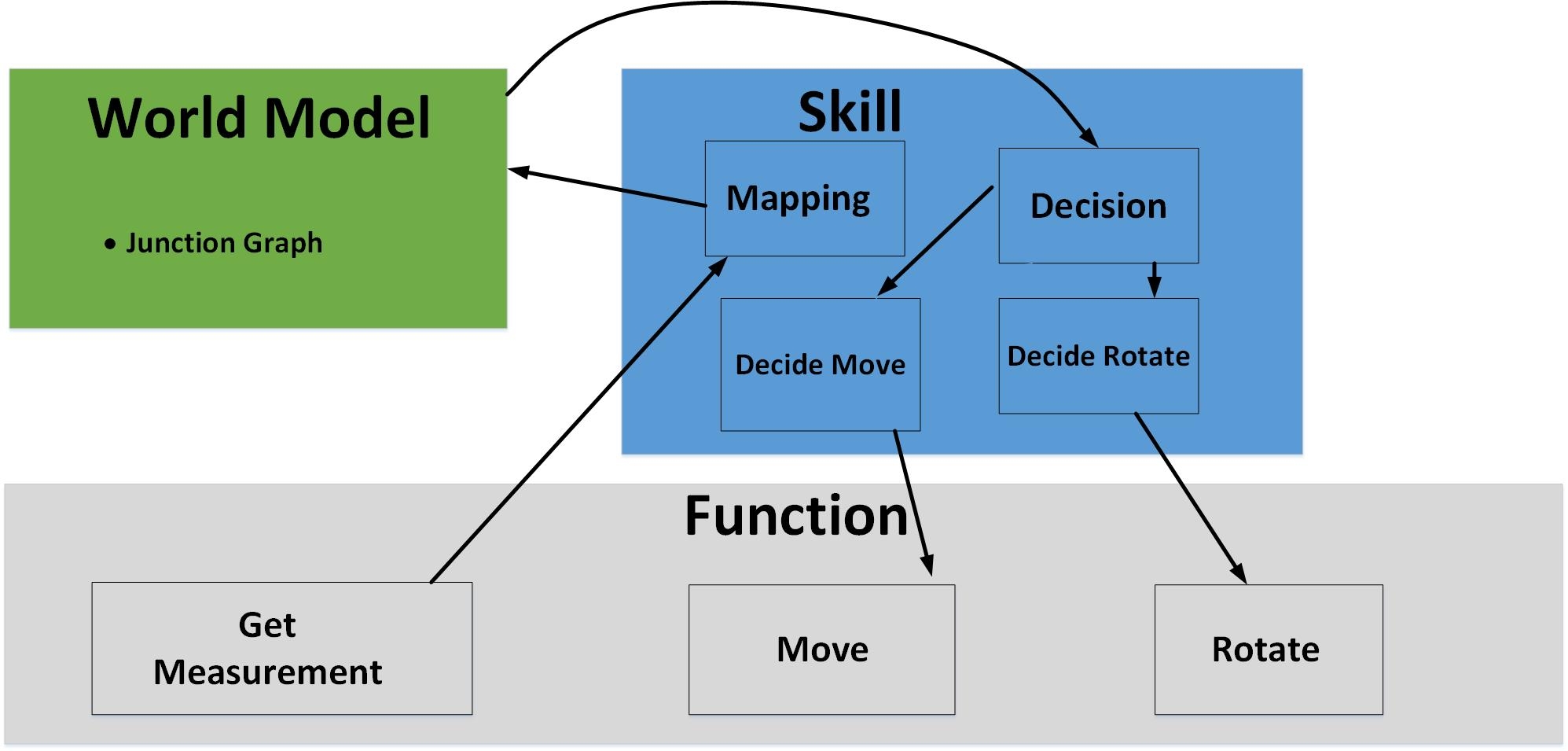
The odometer and LRF generates data for mapping the environment.
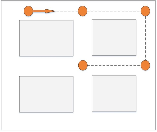
The algorithm sets nodes on the junction as a setpoint for navigation, plans the route and put the actuators to work accordingly.
The odometer and LRF keeps on keeping track of the environment and the software recognizes obstructions, dead ends that might be doors and junction.
Corridor challenge
design
At first, PICO moves forward with a modified potential field.
When it detects the junction, the potential field goes off and stops when it is in the middle of the junction.
PICO then rotates 90 degree and moves forward.
When PICO detects that it is inside the junction, the potential field goes on and finishes the challenge.
result
The corridor challenge failed
In the first trial PICO moved straight forward without potential field.
When it detects the junction it stopped and rotated 90 degrees in the wrong direction.
This inevitably resulted into crashing into the walls.
The second trial PICO did not detect the junction and drove straight forward, this was the latest program.
evaluation
The first trial used our old program that has proven itself as seen in the video below. Unfortunately we did not push the correct version to PICO.
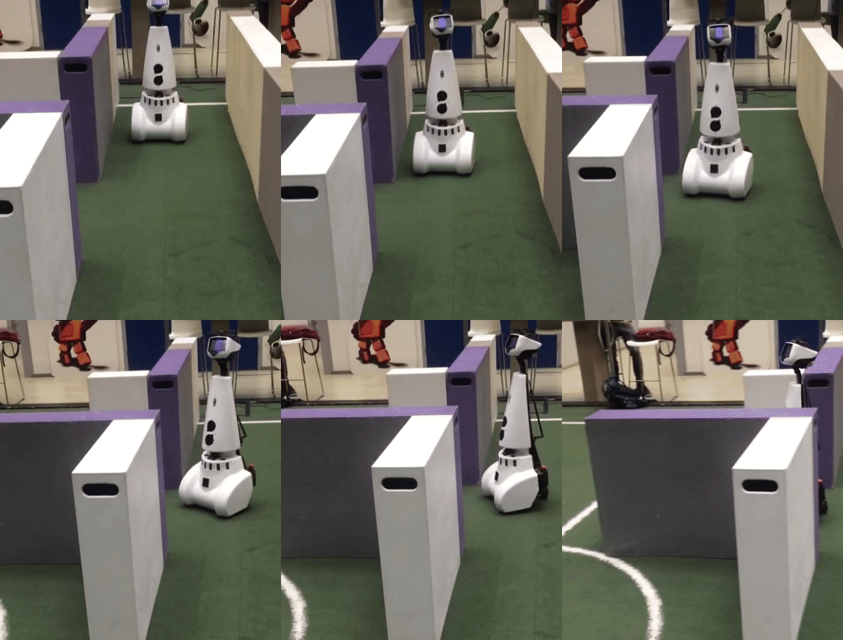
The second trial used our latest program. Potential field is added because there exists a chance that PICO would run into the walls without it.
The new program works in the simulation, it has been tested in the real setting and we had problems with the odometer to correctly make the turning.
The program had to run without debugging in the real setting. Later on, a bug was found in the junction detection.
Maze challenge
design
architecture
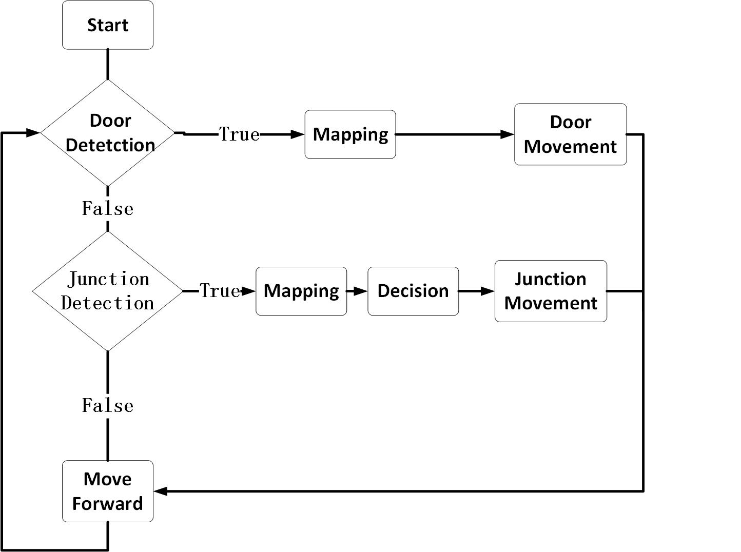
main flow
detection
door detection
junction detection
In the following picture, it is clear that three laser bundles in forward, minus ninety degree and plus ninety degree are selected to detect the junction. In order to find junction in perfect way, the detection radius and detection angle need to be well calculated.
 [math]\displaystyle{ Insert formula here }[/math]
These two equations will make sure the pico can find junction in thw widthest corridor and also could go through the junction in open loop. Finally, the detection radius is set to be 0.85.
To increase the robust of the detection, all the distance of the laser line inside the laser bundle will be measured, if 80% laser line has longer distance than the detection radius, PICO will consider there is a junction.
door open detection
movement
door movement
junction movement
move forward
Similarly to the junction_movement.cpp, move_forward.cpp uses three front laser sectors to adjust the speed. The forward speed is either 0.5m/s when the detection allows or -0.2 m/s otherwise. What differs from the junction_movement.cpp is that the forward movement will not stop when it adjusts with the side movement to avoid obstruction. With 6 laser sectors, 3 at both sides, it adjusts the sidewards speed. When it detects a obstruction, it will move sidewards to avoid the obstruction.
code snippet: move_forward.cpp
mapping
protection
open space
result
evaluation
Evaluation group9 EMC 2017
Code snippets
Movement
code snippet: move_forward.cpp
code snippet: junction_movement.cpp
