PRE2016 3 Groep15: Difference between revisions
| Line 64: | Line 64: | ||
Ultimately these scripts give a calculated energy and time respectively. These variables will be implemented in the simulation of the robot. This way the total amount of energy and time can be calculated to build the given house. This way, for each model put in, the needed efficiency and time to build the design can be presented. | Ultimately these scripts give a calculated energy and time respectively. These variables will be implemented in the simulation of the robot. This way the total amount of energy and time can be calculated to build the given house. This way, for each model put in, the needed efficiency and time to build the design can be presented. | ||
==== | ==== Improvements and ideal concept ==== | ||
At the moment the movements calculated are relatively simple. It would be preferable to be able to make calculations for more complex movements, using all the differents available motors. A more complex kinematic model would be needed to transfer positions into angles. | At the moment the movements calculated are relatively simple. It would be preferable to be able to make calculations for more complex movements, using all the differents available motors. A more complex kinematic model would be needed to transfer positions into angles. | ||
Revision as of 16:27, 27 March 2017
Group Members
| Name | Student ID |
| Martijn de Boer | 0907480 |
| Josja Geijsberts | 0896965 |
| Gijs Herings | 0953862 |
| Martin van Leeuwen | 0901497 |
| Max van Meer | 0951669 |
| Bart Tulkens | 0956335 |
Introduction
In the construction sector, building is still largely manual labor or aided by tools, but not automated. Some companies have tried to automate building construction by 3D printing layers of cement. This however, is not the only or the best solution. Pouring cement in this way generally leads to it not being reinforced concrete. If prefab components are grabbed and stacked to build a construction, electronics and piping can be built into the construction easily.
In this wiki page, a solution for an automated construction robot which places prefabricated building blocks, its advantages and disadvantages and how this can be achieved will be explained. The first idea was to build a simplified prototype, which used Duplo blocks to autonomously build. However, after thorough planning and analysis, this plan was discontinued. The main reason was that this solution would be too time consuming and the other aspects of this project would receive too little attention. A new plan was developed, with a new goal. The new goal is to develop a functioning simulation with a user-friendly interface. Alongside the simulation, a detailed model will also be made. To achieve this goal, a couple experts in construction discipline will be contacted.
Automation in construction
Past
Present
Future
Initial Plan: Prototype
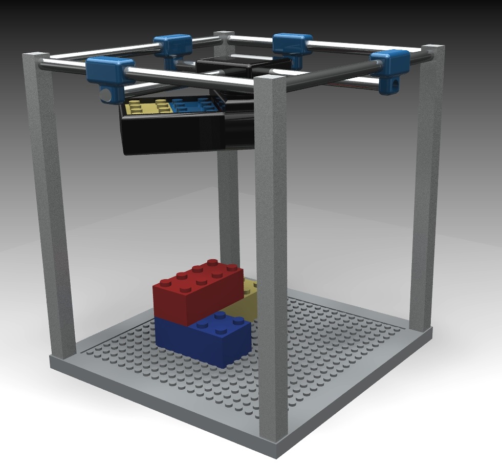
Initially, the goal was to develop a functioning, small-scale prototype. This prototype was to pick up and stack Duplo blocks basen on a given building plan as input. A 3D-model of this concept can be found in Figure 2. However, after thorough investigation, it was found that the achievability of this prototype was too low. A lot of small scale problems would have to be solved whilst there would not be enough time to discover and analyse the full-scale problems. It was therefore decided to discontinue the development and research into the prototype.
Renewed Plan: Simulation and Model
The new goal is to develop a functioning simulation with a user-friendly interface. Alongside the simulation, a detailed model will also be made. The simulation should be able to, on user input, provide the path that the printerhead should follow in order to build the desired building. This user input is yet to be determined, though, preferably, the input will be the output of a commonly used program for the designing of buildings. In this manner, the designer is not flooded with extra tasks. The interface should thereby also be self-explanatory and easy to use. The model will show a detailed concept of what the construction robot is expected to look like. The model will likely also lead to various designing issues that will be addressed in the upcoming weeks.
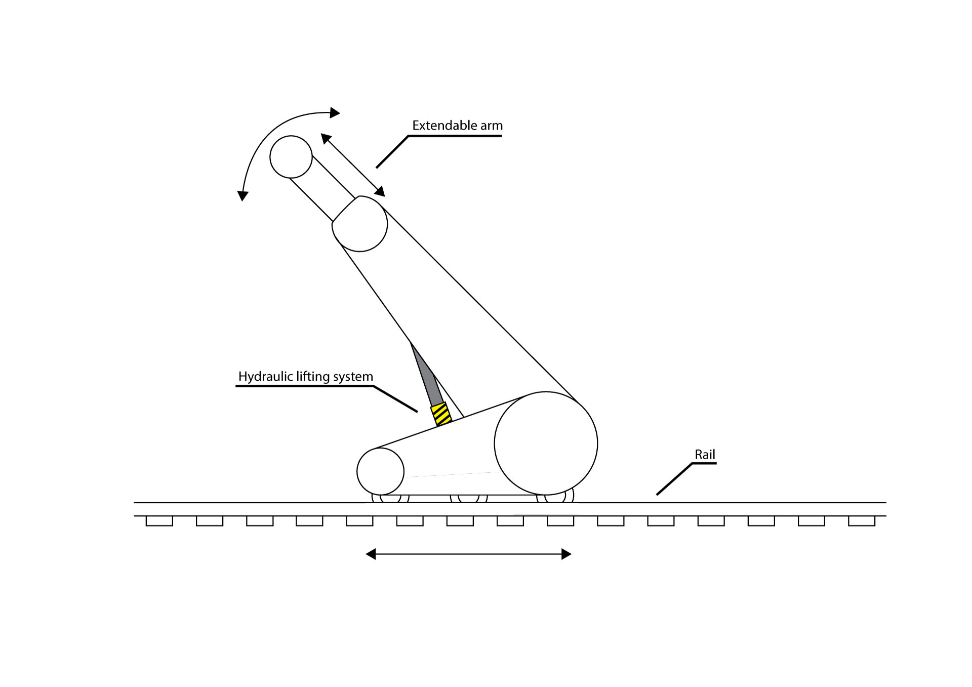
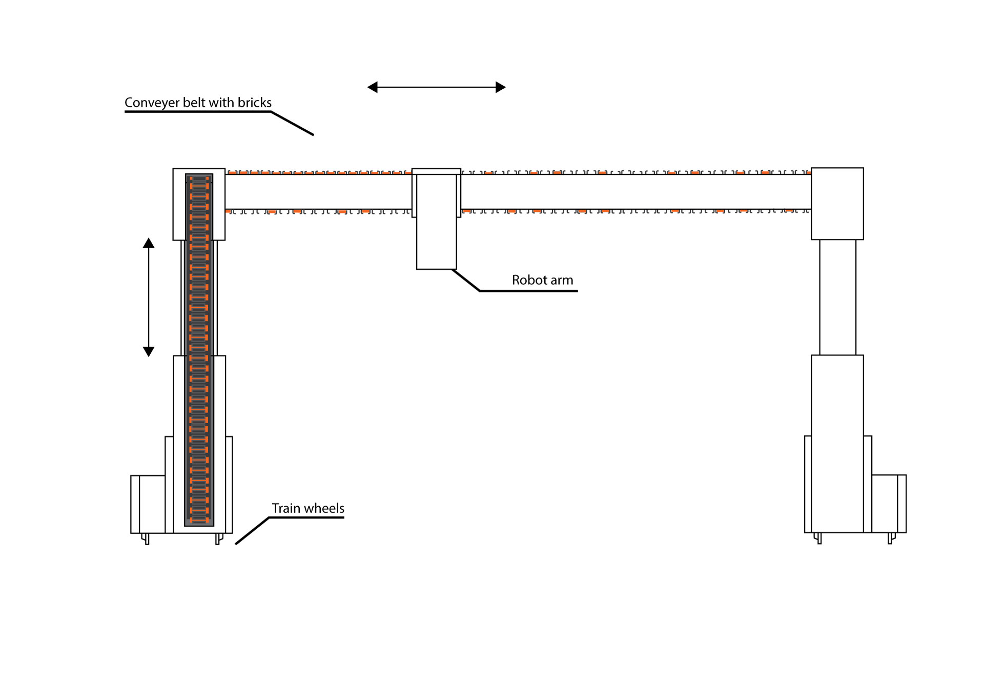
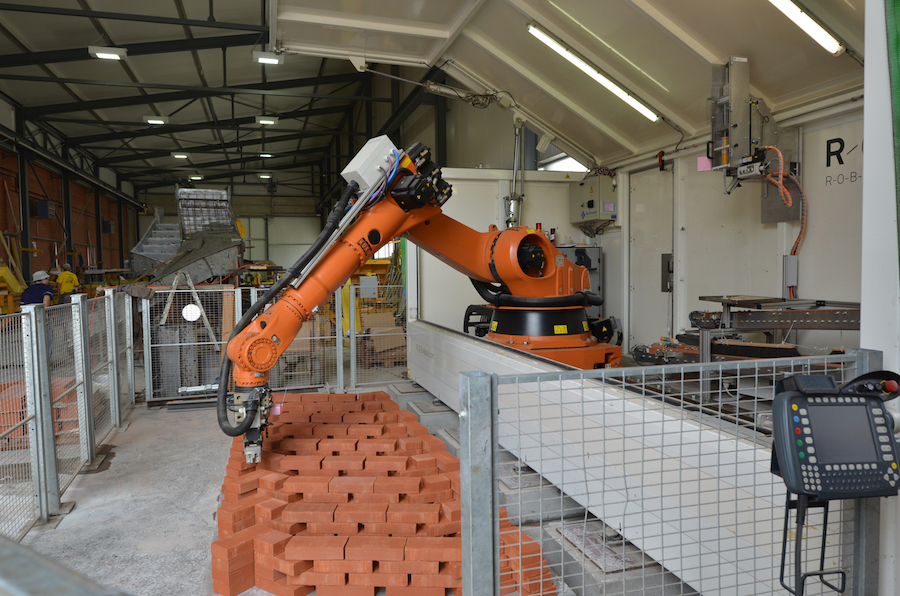
The side view of the final design can be seen in figure 1, while the front-view can be seen in figure 3. In figure 1, you can see the possible movements of the construction robot and the most special parts. The design is based on a concept of [Behrokh Khoshnevis]. The main difference between his concept is the fact that his design uses concrete to print, while the provided solution functions with bricks. In figure 3, a brick providing solution is implemented in the design. The orange blocks represent bricks, while the gray part represents a conveyor belt. Left from the robot arm the conveyor belt is filled with bricks, while at the right side, it has already used most of the bricks. The conveyor belt loops back to the beginning where it gets refilled. The whole system can be refilled with bricks by inserting brick stacks in the left side. For now, the robot arm is displayed by a rectangle. This is not representative for the concept. The robot arm should look like the one in video, and thus like a smaller version of the robot arm in figure 4.
Simulation: Energy and Time robotarm
Robotarm
When construction robot has arrived at the desired position, a recurring set of movements will have to be done to place the bricks. This will be done by a smaller more accurate robotarm. The robotarm has to pick the bricks up, go past the cement dispenser to dispense cement on the bottom and the side and place the brick securely.
Energy
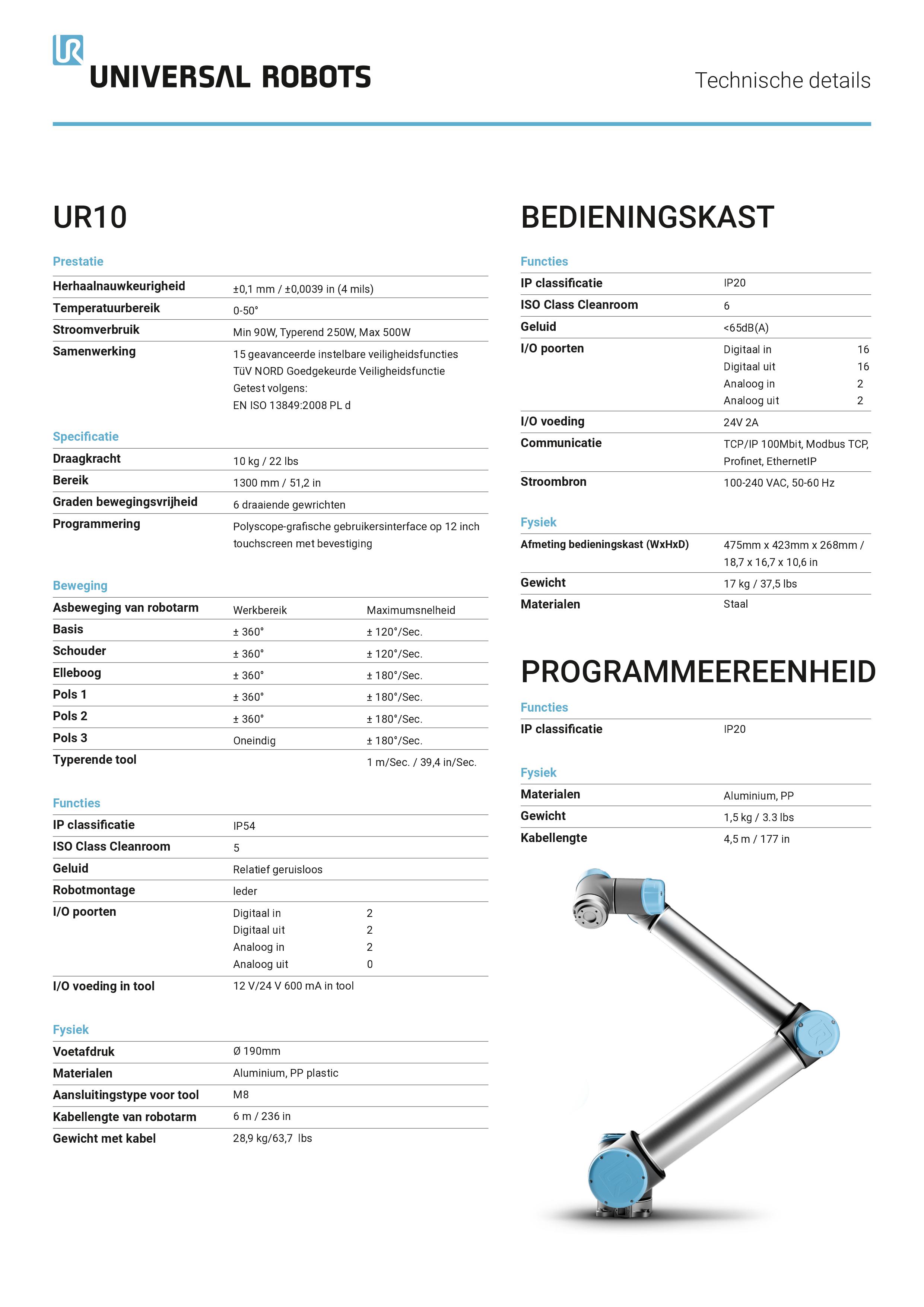
To calculate how much energy this would cost, the robot shown in Figure 5 is taken as an example. Then the moments of inertia of several parts are calculated/estimated. Followed by the estimation of the speed changes that every movement needs. Then the work is calculated of every movement and added together. Since motors are not 100 percent efficient, is the total work divided by an estimated efficiency to get the estimated energy for one placement cycle.
Time
To calculate the time, a kinematic model of the given robot has been made. This model changes the wanted x and y coordinates (of the robotarm relative to the conveyor) into the needed angles for those given coordinates. Then the difference between the angle of this situation and the last situation is calculated. The maximimum speeds from the robot specs are taken and multiplied by the angle differences to calculate the time needed for that movement. Some movements however are happening simultaniously, so the movement that takes the longest time to execute only get added to the total time of the brick placing movement.
Implementation
Ultimately these scripts give a calculated energy and time respectively. These variables will be implemented in the simulation of the robot. This way the total amount of energy and time can be calculated to build the given house. This way, for each model put in, the needed efficiency and time to build the design can be presented.
Improvements and ideal concept
At the moment the movements calculated are relatively simple. It would be preferable to be able to make calculations for more complex movements, using all the differents available motors. A more complex kinematic model would be needed to transfer positions into angles.
Also there is a big estimation of the time used for the hand to grab a brick. This part of the arm could be worked out more, when the actual hand would be chosen. This way the calculations could become more accurate. The same idea holds for the arm itself. The masses of the various parts are estimated and when more information about it are present, the calculations could be improved.
There is not only one type of brick used, there are many different kinds of bricks. Bricks with different dimensions and different weigths. These parameters influence the movement and energy and calculations. What would be ideal, is that the chosen brick parameters can be put in or even chosen from a database. With these parameters, the models will then calculate the required time and energy.
Users
In the design of the robot and the software the user will play a vital role. It was therefore important to have discussion with a potential user of such a robot to see how they design. We managed to arrange an interview with Thijs Kruiselbrink PHD student of the faculty "Bouwkunde" at the TUE and asked him the following question.
What workflow do you use to design houses? Currently the Autocad software is most commonly used to design houses. Autocad is a 3D modeling software from autodesk capable of exporting 3D models in many different formats. Alternatively Bim is also starting to get more popular. Bim is very usefull since buildings are constructed virtually within the software itself, which allows its users to find problems with the design earlier.
From this we conclude that we will need a format that Bim and autodesk can export as the input for our simulation so it integrates nicely with the workflow of architects
Construction robot simulation
To simulate and visualize the construction robot the math lab programming language is used. The program works by loading a STL model into Matlab using already existing software. The program will use the vertices and faces from these model to determine where and in what order it will place it blocks. Requirements The model will be able to
- Import any 3D model with exported in the STL format
- Successfully visualize the construction of a building from a model containing only rectangular shapes.
- The system should be relatively user friendly
- The system will use a proper pattern when placing the bricks to ensure stability
- The simulation will be able to deal with half bricks and tell the user how it needs certain bricks to be cut
Milestones
- Import a 3d Model
- Initialize a Grid/matrix that represents a building space.
- Determine which coordinates in the grid are (in) a wall from the faces.
- Determine which coordinates in the grid are (in) a wall for different heights.
- Define where bricks should be placed.
- Define in what order the bricks should be placed.
- Create a user-interface
USE Aspects
Below, a short overview of USE aspects is given.
User
- The construction robot will reduce the workload of the construction workers.
- The construction robot will reduce the amount of danger construction workers are exposed to.
- The construction robot will lead to a quicker realization time of the building, which in turn leads to quicker accessibility for potential future residents.
- The construction robot will enable more possibility for personalized designs
Society
- The quicker realization time of buildings the construction robot provides, will lead to a more efficient construction sector, which in turn leads to:
- The construction sector being more able to keep up with society’s demand for more living room.
- Possibly lower house costs due to reduced construction costs. This makes owner-occupied houses more accessible to a bigger audience.
- The construction robot could be used for building aid in third world countries.
Enterprise
- The quicker realization time of buildings can save construction companies a lot of money due to being able to do more projects in less time.
- The construction robot can save construction companies money on wages for construction workers
- The construction robot can help construction companies compete better on the market.
Potential Users
Larger scale
When looked at form a large perspective, mainly the construction robot will be important for construction companies. A construction robot will have a lot of benefits for these companies such as decreased building time. It will envigorate the market encouraging competition. Possibly being a major factor in the succes of certain construction companies.
Third world charity
The construction robot could also possibly be is used in development projects in third word countries. The fast building robot could make simple houses for people in the slums of big cities for example. This would be fast and very efficient since the homes would not have to be complicated with all kinds of personal wishes from the people who would be going to live there.
Smaller scale
When looked at more in detail the direct users of the robot will be construction workers. Their daily work pattern will be impacted heavily. More use of controls and repairing will be needed and less actual building. Possibly different kinds of people will be needed at a construction site because of that.
Private use?
When look at private users there is not any significant value in a construction robot. Maybe a smaller model as big as the prototype could be interesting as a hobby project, but most people won't be able to control the robot. Therefore the robot is mostly suited for professional or charity use.
General planning


The general planning is displayed in a GANT chart, which can be seen in figure 6. Because of the major change in the deliverable, a new planning had to be made. The old planning is visible in figure 5. In the GANT-chart activities, the work distribution and milestones can be seen. The planning will be adjusted if necessary.
week 1
- Deciding on the subject of the project
- Preparing the presentation about the concept.
week 2
- Concept Presentation
- Preparing the second presentation about the planning.
- Start working on wiki, explaining the concept and the deliverables
week 3
- Planning Presentation
- Rework project based on feedback
- Arrange meeting with TU/e Concrete Printing
- Start creating a list of required components for the deliverable
- Start working on the enterprise plan: Potential Users
- Update wiki
week 4
- Milestone: Order components for the deliverable
- Start desiging and printing components for the deliverable
- Finish Potential Users
- Start working on the enterprise plan: Social impact
- Update wiki
week 5
- Work out new deliverable
- Start working on the enterprise plan: Estimated costs
- Finish Social impact
- Update wiki
week 6
- Finish Estimated costs
- Start working on the enterprise plan: Business proposal
- Milestone: Illustrations of final design
- Update wiki
week 7
- Finish Enterprise plan
- Milestone: Business proposal
- Milestone: Simulation, Model and User interface
- Update wiki
week 8
- Buffer week
- Prepare final presentation
- Update wiki
Action plan
The initial step in the assembly of the robot is to get the green light for its creation. To ensure that the scope of the project is indeed properly defined. Once the theoretical background is sufficiently explored the construction of the robot can start. The construction can be divided in a few segments.
- Acquiring the required components
- Physical assembly
- Calibration
- Software implementation
- General Debugging
Action plan renewed
Originally the plan was to build a prototype, however that is no longer the case. We are going to emphasize on a simulation. This means that we don't have to wait on parts or a budget, but can work on our computers by ourselves. The plan right now is to develop a script that can make a 3D map in a matlab enviroment from a stl file taken from NX. Besides that a script has to developed that determines and executes the best path of for the robot to place the bricks. While in this script the actual position of the smaller robot arm is not simulated, the energy and time it takes to execute its actions have to be taken into account and calculated. These parameters have to be implemented in the placement script, so the placement script can give energy and time costs as output. When these objectives are met and are working, other aspects can be elaborated into. These aspects can for example be different brick laying styles or more complicated building shapes instead of lines with right angles
- Translating NX to Matlab environment
- Develop path making algorithm
- Calculate and implement energy and time costs
- Testing and refining
- General Debugging
- Elaboration into new aspects