Experiments: Difference between revisions
No edit summary |
|||
| Line 74: | Line 74: | ||
It isn't still a clear pattern, so we've to improve the algorithm a bit more. But with this method, it will be able to measure the sleepcycle. See the appendix below for the Matlab-scripts. | It isn't still a clear pattern, so we've to improve the algorithm a bit more. But with this method, it will be able to measure the sleepcycle. See the appendix below for the Matlab-scripts. | ||
== Justification of algoritm == | |||
We will check if the measured sleepcycle-graph is right. We will check this by measuring the sleepphase on two several methods at the same time. One method is or course with our own algortim. The second method will be with the an application on our smartphone. The application is named SleepCycle. (see literature for more information about the App and how they measure the sleepphase) | |||
== Appendix == | == Appendix == | ||
Revision as of 12:04, 17 March 2016
Back to main page: PRE2015_3_Groep4
Measurement plan
Research question
Is it possible to know in what sleep phase a person is by analyzing the sounds that he/she makes while breathing?
Sub-questions
• What is the best way to measure the sound present in the bedroom?
1) High-frequency recording of the sleep measuring the pitch
2) Low-frequency recording of the sleep measuring the decibel level
• What conclusions can be drawn from the results we encounter?
What has to be done
• Measuring
1) Measure the sounds of multiple persons their bedroom throughout the night.
2) Measuring multiple nights.
3 ) Measuring on a high-frequency sound level as well as on a low-frequency sound level.
• Processing the measuring results
1) Analyzing which method brought us the best results.
2) Determining if it is possible to use the data that we have for future work.
What are we going to use for the measuring
For the measuring of the sound levels, an Arduino is used. This Arduino will be connected to a sound detector. We chose an Arduino Mega with a SparkFun Sound Detector. The results will be stored to be reviewed afterwards.
When and where do we do the measuring
The testing will be done as soon as all the components arrived. The plan is to do as many tests as possible in about one week. Two persons will do the testing at their own home. This way there are twice as much testing results in the same time period.
The sound detector was recommended to us by Ruud van den Bogaert. It is more that suited for our needs, for it has both analogue frequency output and volume level or ‘envelope’ output. It also has a digital output that’s high when the volume rises above a certain threshold, which we won’t use.
Measurements
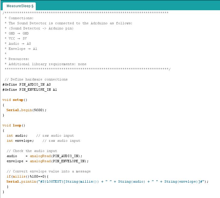
First, we wrote a program which will print as fast as possible the time, audio and envelope. These output will be logged on the computer during the sleep. The time will be in microseconds anywhere between 0 and 2^32, which is around 71 minutes. The audio is an analog value between 0 and 1023, which will be typical around 510. The envelope is an analog value which represent the amplitude of the sound. The value of the envelope is between 0 and 1023 and is typical around 6. See the appendix at the bottom of the page for the Arduino code.
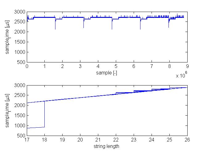
After a night, there are almost ten million lines of data logged. These data can be implement on Matlab. Matlab will first 'repair' the time. Because 71 minutes is the highest value the arduino can print, the arduino will begin several times at 0 during one night. This have to be 'repaired'. After that, there will be made plots to analyse the logging-proces. For example the sample time against the number of samples and the sample time against the string length are plot, to analyse and improve the sample frequency. This plots show that how longer the string, how higher the sample time.
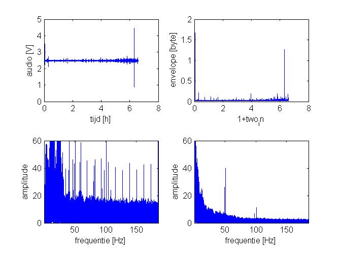
There are also plots of the audio and envelope against the time, and the amplitude of both against the frequency.
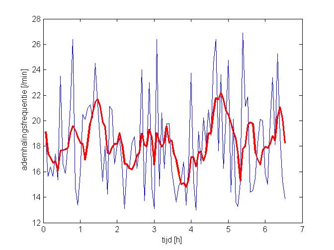
After that, the data will be used to make a graph of the frequency of the respiration. The data of the envelope are used. First, there will be made frames of 4 minutes. After that, fft will be used to get a graph of the frequency and their amplitudes. Out of this graph, only the frequencies between 13/min and 27/min will be analysed. This, because we've then lost the main part of the noise, while the frequency of the respiration is still there. The frequency of the breath will namely be between these frequencies. Out of the remaining frequencies, the frequency with the highest amplitude will be determined for every frame. The associated frequency will be plot for every frame over the time. Now, we've an graph of the frequency of the respiration durint the night.
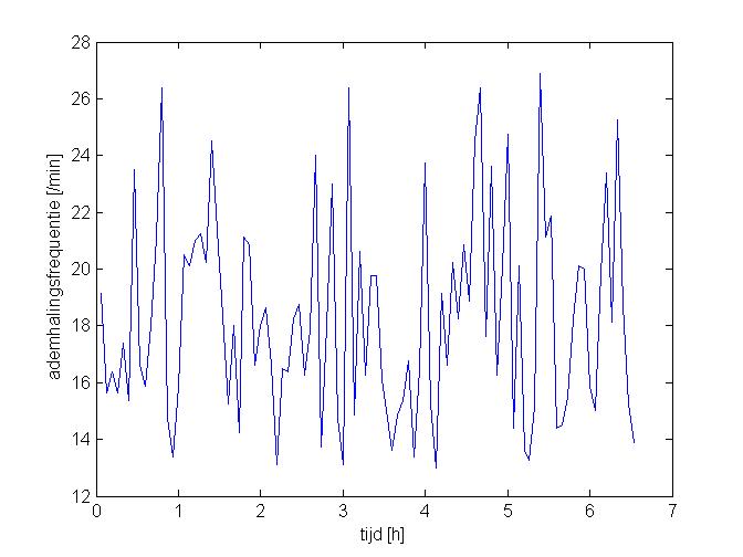 The data is from a real measurement (10-3-2016)
It don't seems to have a clear pattern. But when you plot an sliding average of the last five frames (red thick line), there will appear a more clear pattern.
It isn't still a clear pattern, so we've to improve the algorithm a bit more. But with this method, it will be able to measure the sleepcycle. See the appendix below for the Matlab-scripts.
Justification of algoritm
We will check if the measured sleepcycle-graph is right. We will check this by measuring the sleepphase on two several methods at the same time. One method is or course with our own algortim. The second method will be with the an application on our smartphone. The application is named SleepCycle. (see literature for more information about the App and how they measure the sleepphase)
Appendix
Arduino-code:
Matlab-scripts:
This script will transfer compact data into graphs of analysing the data and the Arduino code:
This script will use the output of the script above to make a graph of the frequency of the respiration during a night:
