Robot control software: Difference between revisions
No edit summary |
No edit summary |
||
| Line 9: | Line 9: | ||
=== Programming the Localisation === | === Programming the Localisation === | ||
We created a square field in which the robots would be present the entire time. The center of the field would have the coordinates (0,0). Since the field is 2 x 2 meters and distance in the code is expressed in centimeters, the corners of the field have the following coordinates: (-100, -100), (100, -100), (100, 100) and (-100, 100). | We created a square field in which the robots would be present the entire time. The center of the field would have the coordinates (0,0). Since the field is 2 x 2 meters and distance in the code is expressed in centimeters, the corners of the field have the following coordinates: (-100, -100), (100, -100), (100, 100) and (-100, 100). | ||
A schematic representation of the field is given: | |||
[[File:Field.jpg]] | |||
To begin, first the following information should be a given for the robot: | To begin, first the following information should be a given for the robot: | ||
Revision as of 17:34, 17 January 2016
Place Robot Control Software Pseudo-code and src-code here.
Localisation
The localisation of the robots is a very important part of the project. With localisation, the robot is able to keep track of its own position and direction. This is of high importance when a robot encounters a heavy object, because now it can find out which robot is the nearest to him and ask this specific robot for help. Besides the localisation, also a bluetooth-communication script is necessary to accomplish this. The way this communication is drafted and scripted is written in Bluetooth Communication.
Programming the Localisation
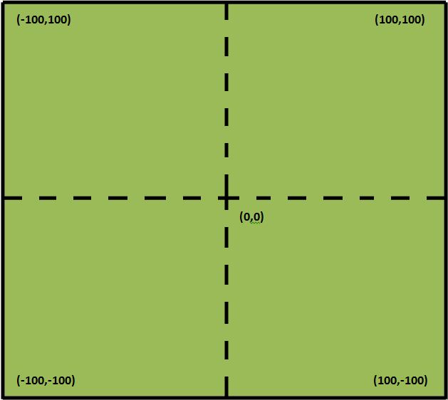
We created a square field in which the robots would be present the entire time. The center of the field would have the coordinates (0,0). Since the field is 2 x 2 meters and distance in the code is expressed in centimeters, the corners of the field have the following coordinates: (-100, -100), (100, -100), (100, 100) and (-100, 100). A schematic representation of the field is given:
To begin, first the following information should be a given for the robot:
- Its beginposition (x- and y-coordinate)
- Its begindirection (angle of its direction with respect to the x-axis)
From this point on the rotation sensor inside of the actuators used for the NXT Robots are used to keep track of the robot's position. When the wheels of the robot are rotating, the robot is either going forward, going backwards or turning. This has to be taken into account when converting the steps of the motor to either angle or distance.
When the robot is going forward, the rotation sensor counts the steps that the actuator makes. These steps are then converted to a distance in the java script. To calculate this convergence factor, the robot was programmed to drive forward and continuously print the steps of the actuators on its display until the pressure sensors gave a value above zero. Next, the robot was placed at an exact distance of 1 meter from a heavy object. After hitting the heavy object the values of step was read and the convergence was calculated by dividing 100 by the amount of steps. This gave us the amount of steps per centimeter. This was done 3 times and the average value was exactly 35 steps. So in conclusion, from here the robots were able to drive a given straight distance with an inaccuracy of approximately 1 cm.
This same principle was used to establish the amount of steps per degree of turning. We entered an amount of steps (positive for one actuator, negative for the other) so the robot would start turning. This was done until the amount of steps for turning 360 degrees was known. After this the convergence factor from steps to degrees turned out to be 5/31.
From here we were able to make the robots go to any given position. However, an inaccuracy of approximately 5 degrees was found in the turning of the robots, due to slipping and the inaccuracy of the rotation sensors in the actuators themselves. This lead to the fact that when the robot was following a route, the inaccuracy of keeping track of its location, increased after every turn the robot made.
The way the convertion of steps to distance and degrees is programmed, is shown below:
Hier het script dat de tachocount omzet naar degrees en afstand
As you can see, the Tachocounter (rotationsensor of the actuator) is reset before it starts moving straight, backwards or starts turning. Also the script shows that the robots will move straight ahead for the amount of 10.000 steps. This is a random high number. This means that the robots will move straight ahead until they end up in another state. Other states the robot could end up in are:
- The "Out of Bounds" state, where the robot has reached one of the borders of the field.
- The "Go to object" state, where the robot encounters an object.
- The *Asking for help" state, where the robot determines which robot is nearest to him and asks this robot to help him.
- The "Going to help" state, where the robot is on its way to another robot that needs help, pushing a heavy object out of the perimeter.
Out of Bounds State
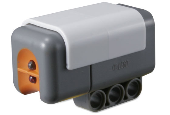
Each robot is equipped with a light sensor that points to the ground. This light sensor is shown in the Figure below:
The area in which the robot should stay is set up with tape that has a different color than the surface the robots are driving on.
Whenever the light sensor of a robot detects the change of light intensity, caused by the tape, the robot will end up in the "Out of Bounds" state.
The script for this state is shown below:
Script gedeelte "out of bounds" state
This code shows that whenever the robot reaches the tape, it will go backwards for 30 centimeters and will then turn 120 degrees. After this the robot goes back to the first state in which it will drive straight again.
Go to Object State
Every robot is also equipped with an ultrasonic sensor which can detect objects. When this sensor detects an object within a distance of 40 centimeters, it will drive towards it. The code for this state is shown below:
Script gedeelte "go to object" state
This code will make the following things happen:
- When the robot drives over the tape, it will return to the "Out of Bounds" state.
- When the robot encounters the object and the object is heavy enough to press in either the left or the right pressure sensor, the robot will go to the "Asking for Help" state.
- When the robot is asked for help before it has encountered the object it will go to the "Going to Help" state.
In short, this will make sure that when the object is light enough not to press in one of the pressure sensors, the robot will push the object out of the perimeter. When the object is so heavy it will press in one of the pressure sensors, the robot will ask for help and when the robot is asked for help by another robot before it encountered a heavy object, the robot will go and help the other robot instead.
Asking for Help State
Whenever the robot is in this state, it means it has encountered an object which was heavy enough to press one or both of the pressure sensors. From here the robot
Communication
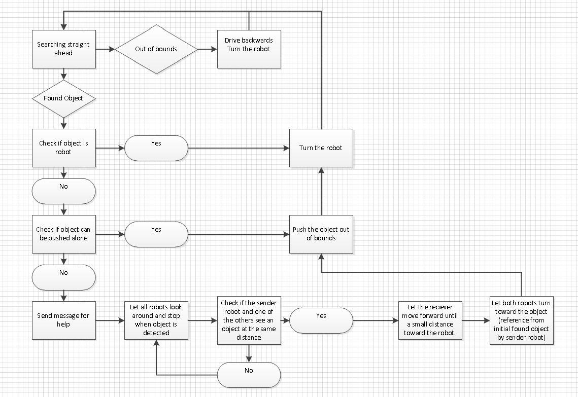
For the behaviour of the NXT robot a state-based algorithm has been used. There are several main states in which te robot can be:
- 1. Searching straight ahead
- 2. Turning
- 3. Found something
- 4. Check if the object is too heavy
- 5. Push the object away
- 6. Ask for help
This behaviour has been visualized in the following flowchart:
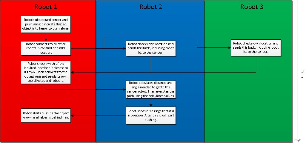
Asking for help will be done using a bluetooth communication protocol:
Back to: PRE2015_2_Groep1


