Embedded Motion Control 2015 Group 9: Difference between revisions
| Line 228: | Line 228: | ||
= Corridor Challenge = | = Corridor Challenge = | ||
http://youtu.be/wFrfn02jlCg | |||
= Testing PICO = | = Testing PICO = | ||
Revision as of 20:51, 25 June 2015
Group Members
| Name | Student nr | |
|---|---|---|
| Prasanth Muralidharan | 0926106 | p.muralidharan@student.tue.nl |
| Arkadiusz Kamrowski | 0921901 | a.l.kamrowski@student.tue.nl |
| Marcin Turemka | 0921893 | m.turemka@student.tue.nl |
| Kartik Mundaragi Shivakumar | 0926061 | k.mundaragi.shivakumar@student.tue.nl |
| Manikandan Manjaparai Sundaram | 0926898 | m.manjaparai.sundaram@student.tue.nl |
| Anurodh Mishra | 0927142 | a.mishra@student.tue.nl |
| Dennie Craane | 0834726 | d.w.h.craane@student.tue.nl |
| Sujit Sharan | 0924962 | s.sharan@student.tue.nl |
| Anshuman Singh | 0927466 | a.singh@student.tue.nl |
Objective
The main objective of the course is to design and implement an embedded motion system and apply this to an autonomous robot. At the end of the course, there is a maze challenge in which the robot has has to find the way out as quickly as possible.
Robot
For implementing and testing the software design, robot named PICO is used. There are mainly two inputs for the PICO robot. They are (1) odometry data which is received from the wheels and (2) laser data from the range finder.
Design
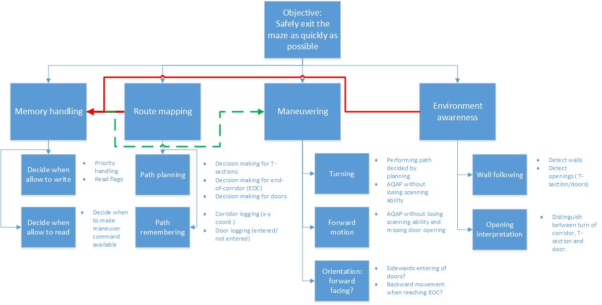
To reach the objective, the robot will have to fulfill a set of functions or tasks, for which it will need certain skill sets. In order to judge whether the found solution fulfills the functions, a set of requirements and necessary components are needed to meet the specifications. The functions and underlying skills can be portrayed in graphical overview resulting from brainstorming as shown in the above figure.
For each function, requirements can be set along with additional information about the required components and specifications. The resulting skill sets and robot lower layer abilities that a re needed are derived from the combination of the functions and components.
Function: Memory Handling
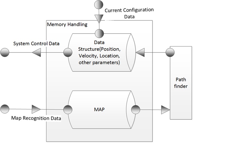
As seen in the figure above, this function is mainly involved in handling the on-board memory modules for all the computations and logical decisions required to be made by the robot.
Requirements and specifications
1. Data structure depends on applied control/path finding algorithm. 2. Data has to be dynamically allocated. 3. Data dynamically available for the system architecture. 4. Appropriate system elements cannot corrupt, which means, that the synchronization between reading a writing data is required. 5. It should be able to read and manipulate required flags in the robot architecture. 6. It should have a priority scheduling architecture for making decisions in real time within specific time constraints. 7. It Should handle the memory safely without corruption of data.
Components
The components required to perform this function effectively, are a read only code memory, and a RAM(Random Access Memory).
Function: Route mapping
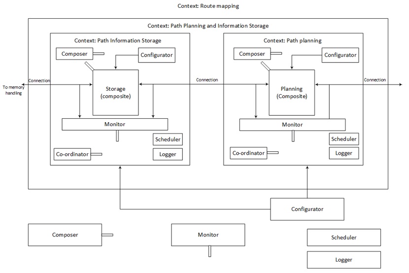
As an example of the approach used, the presented figure depicts the route mapping function as a nested CP which denotes how the functional entities can be designed with CP as the building block at various levels of hierarchy. The main function consists of two sub-functions which have a similar construction to one another. Each of the functional entities operates under its own context which helps in separating the 5C concerns. The ‘connections’ show the exchange of data which in this case is with the memory handling function which depicts the communication aspect with other functional entities.
The function route mapping has the following subcomponents:
Path Planning
- Open corridors first (saving doors encountered in memory): The first step is to scan all the open paths/corridors keeping track of the doors encountered. The doors act as the nodes for the subsequent stage.
- Basic decision algorithm (like left-front-right-down, longest distance, etc.) A basic decision algorithm is required to make the exploration of corridors with branching possible. The base decision algorithm can be a rule of thumb or a more reasoned approach.
- Returning to last saved junction. Encountering a dead end or a loop the robot should return to the last saved checkpoint/junction and continue on the basis of the decision algorithm selected.
- Graphical dynamic programming algorithm - The best possible algorithm with the shortest time is found to be the graphical dynamic algorithm and this would be used to solve the problem for optimal path for the maze.
Path Storage
Path information storage – (co-ordinate system and graphical DP)
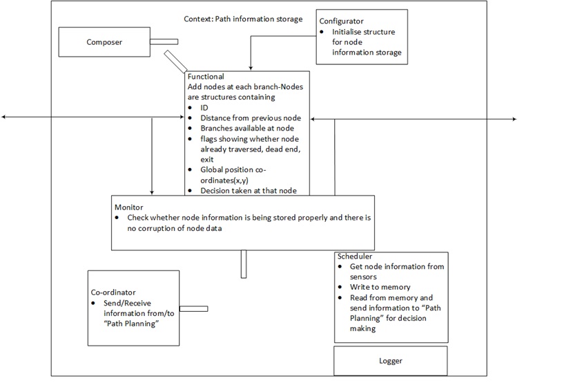
- In order to store the path information a co-ordinate system can be used which helps in the recognition of loops existing in the system. Moreover distance travelled and location of doors can be easily stored with this. However standardization of unit distance as per the movement of the robot (taking into consideration the error in its distance measuring system) is necessary.
Requirement
In order to successfully accomplish the above mentioned function, certain requirements (qualitative in nature for now), needs to be fulfilled. These are:
- Differentiation between open branches and doors in a corridor is required for exploration in an organized manner.
- A nomenclature for the storage of information needs to be agreed upon for ease of understanding and traceability.
Components
- Memory
- Elements (not clearly defined at this level) for conversion of information from robot skill set to suitable parameters like distance travelled, orientation and location w.r.t. a reference.
- C++ code
- An algorithm for path planning
Working
Route map is very important in the maze challenge because the robot should not go to the same junction or corridor which was taken before. So the route map or world map is made of nodes which is used to store the data relevant to the robot for completing the maze. There are some key components used while making the nodes. The nodes acts as a major communicating factor for communication with other function to base their decisions. An identifier was used for storing the information. Depending upon the operation of the robot (turns,exit,door detection), nodes were categorized. The most important task is positioning the robot in the global coordinate when dealing with loops and dead ends.This was also done using the laser positioning system.
The nodes were defined in the code as a separate class with organized structure to ensure ease of access to information.
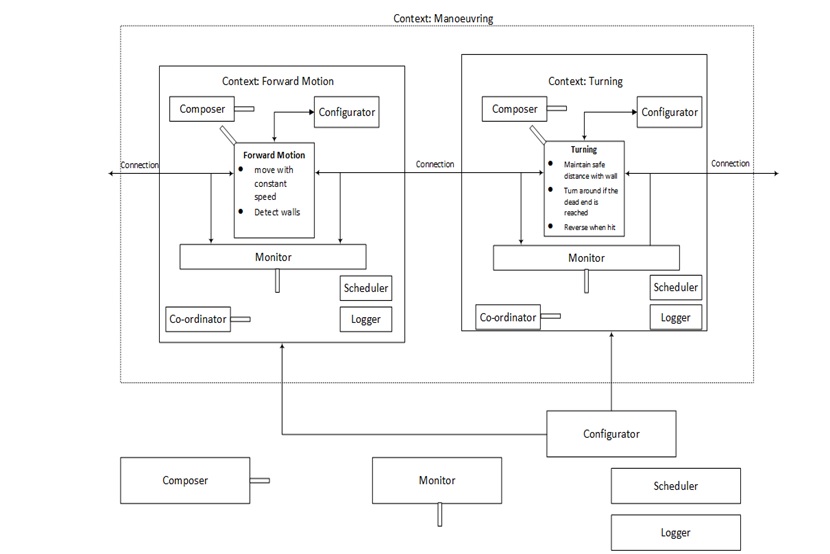
Function: Maneuvering
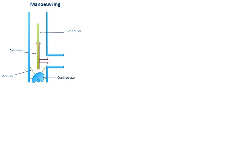
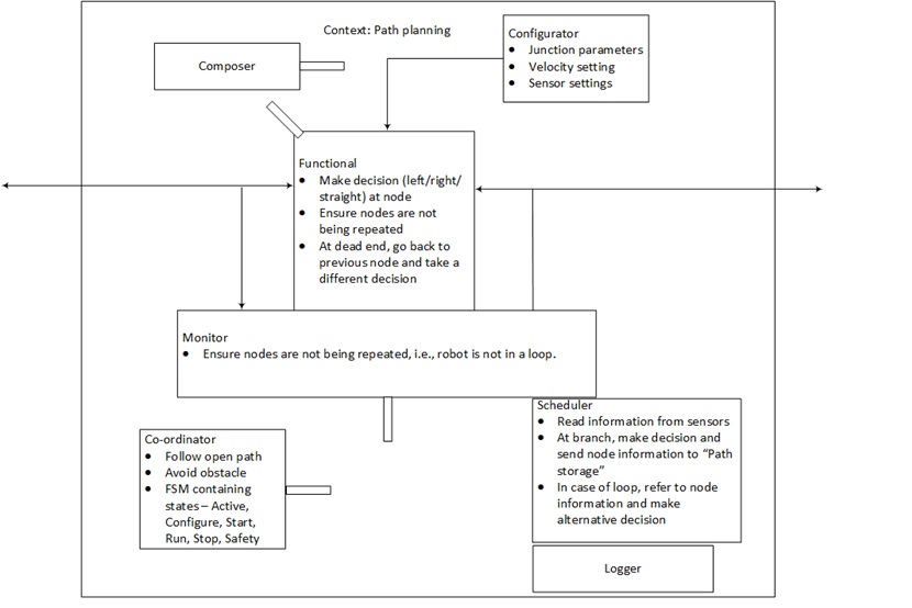
- From the figure above, the 5C principle is clearly understandable in this function. The Monitor senses all the data and condition and sends it to the coordinator. The coordinator receives the data process all possible skills available. Then the scheduler takes the decision and the configurator configures the robot parameters and executes the skill which was decided.
Sub-functions
- Use information from the algorithm and environment to adequately move the robot into the desired position using the abilities from the ROS.
- Maintain a safe velocity and position in respect to the obstacle in the environment, this is to ensure the safety of the robot.
- Optimize movements to reduce time needed.
Requirements
- It must maintain a safe distance with the wall whenever it moves.
- It should move at a constant speed, with which it’s still capable of detecting the door opening.
- The robot mustreverse in the case a wall has been hit.
- If it reaches a dead end it should turn around and return to the last decision location and send a command to the algorithm to recalculate the path.
- If the robot is unable to find a path it might move in backward direction along the same path, so that it has better chance of detecting the doors.
Components
- The robot lower level abilities
- Wheels
- Motors
- Memory
Working
- Centring
- The robot uses to laser data which are perpendicular to the wall to obtained to distance on each side to the wall.
- Further the difference in distance value between the two sides (error) is calculated.
- If the difference is up to a certain threshold value no input or action is taken. How if the error is greater an input is taken in the opposite direction to correct the error. A PID controller is used for centring.
- Cornering
- First the laser range data is scanned for potential corners. The condition used for corner detection is that if there is suddenly change (above certain threshold) in the laser data, that point is marked as a potential corner.
- Once all the available corners are identified, it is stored in the mapping.
- Later the based on the decision making algorithm the selected decision is executed. The robot is moved to the centre of the corner and makes a 90 degree turn and moves forward in that direction.
Function: Environment awareness
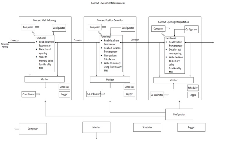
From the figure, it can be seen that the skills are listed in the composition pattern, further these skills in themselves are composition patterns. The skills consist of a set of computations that uses the input from the sensors and gives output regarding the environment ( obstacles, doors, position) to other functions that further process this information. Some skills are shared across the different functionality (e.g. reading data from the sensors and reading/writing of the memory).
The high level function environment awareness consists of tasks:
- Wall following
- Opening interpretation
- Position detection
- Wall detection:
1.The skills and related robot abilities needed to perform this task can be described as:
- Get distance to obstacle from laser sensor for all degrees
- Decide for what degrees an obstacle is present and where not (opening)
- Save obtained information into memory
2.The 5C pattern to perform this task:
- Monitors observes the obstacle distance, based on this the coordinator decides the behaviour of the functionality. For example if the monitor detects a turn or a straight the coordinator configures to take the appropriate action.
- Opening interpretation:
1.The skills and related robot abilities needed to perform this task can be described as:
- Get opening locations from the memory
- Use previous information from the memory to detect ‘new’ openings
- Decide if opening is an exit, door or another branch
- Save information into the memory
2.The 5C pattern to perform this task:
- Sensor data will also detect abrupt stops of the corridor. These openings should be interpreted to be another branch, a door or possibly the exit. This information is also passed to the other functions that can decide which way to go.
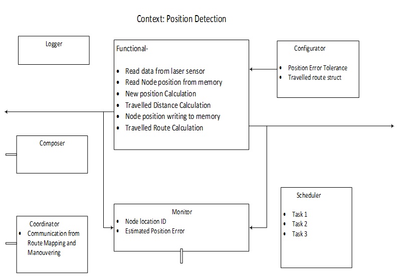
- Position Detection
1.The skills and related robot abilities needed to perform this task can be described as:
- Get distance to obstacle from laser sensor for all degrees
- Get old position from memory
- Compare new distance to old distance and determine distance traveled
- Determine new position relative to starting point
- Save position into memory
2.The 5C pattern to perform this task:
- The position on the map is determined using the sensors of the vehicle relative to the starting position. Also data is processed to determine the local positioning in the corridor. This position info is stored in the memory, where other functions, like route mapping, can use it.
Requirements and specifications
This function should fulfil a set of requirements in order to test if the function is performed correctly. Part of the requirements will be quantitative, however, due to the early stage in the project most requirements are kept qualitative for now.
- The function must differentiate between solid obstacles (wall) and an opening (door).
- Obtained information must be stored in a memory unit accessible by other tasks.
- The memory should be polled with a suitable frequency in order to prevent flooding.
- Detection of obstacles should have a relatively high frequency, due changes in the path (doors)
- Determining global positioning should have a relatively low frequency, due to slow movement speed.
- Upon detection of a door, other tasks should be notified.
Components
Components that are used by this function are the memory and laser position sensor.
Function: Software system architecture
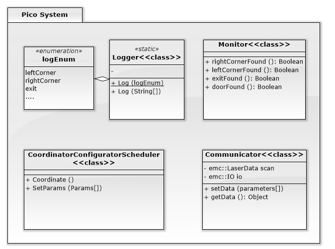
To satisfy
- The composition pattern
- High level code readability
the system was designed in a structured way based on classes. The figure above shows the system architecture with which the entire coding is made.
Corridor Challenge
Testing PICO
Some cool links
Info on git - https://training.github.com/kit/downloads/github-git-cheat-sheet.pdf, http://git-scm.com/ A Micromouse competition video - https://www.youtube.com/watch?v=bproY7G2t4o
