Mobile Robot Control 2021 Group 6: Difference between revisions
| Line 35: | Line 35: | ||
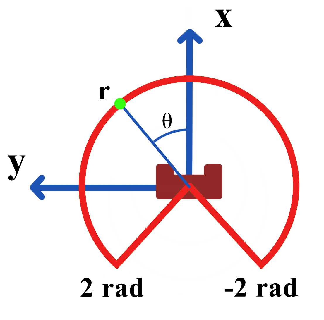
PICO acquires its data points via the laser range finder (LRF). The LRF outputs in one sweep 1000 data points, consisting of the distances (<math>r</math>) corresponding to particular angles (<math>\theta</math>), as shown in Figure 1. The first data point is at -2 rad and the last data point is at +2 rad. Invalid data points above 10 m and below 0.01 m are filtered out. The data points are then converted from polar coordinates to cartesian coordinates using the following geometric equations: | PICO acquires its data points via the laser range finder (LRF). The LRF outputs in one sweep 1000 data points, consisting of the distances (<math>r</math>) corresponding to particular angles (<math>\theta</math>), as shown in Figure 1. The first data point is at -2 rad and the last data point is at +2 rad. Invalid data points above 10 m and below 0.01 m are filtered out. The data points are then converted from polar coordinates to cartesian coordinates using the following geometric equations: | ||
<math>2x \times 4y \div 6z + 8 - \frac {y}{z^2} = 0</math> | <math>2x \times 4y \div 6z + 8 - \frac {y}{z^2} = 0</math> | ||
<math> | <math>y = r_i*\sin(-2 + \Delta \theta * i)</math> | ||
[[File:Pico_coordinates.png|300 px|thumb|right|Figure 1: The coordinate system used with the angular limits of the LRF.]] | [[File:Pico_coordinates.png|300 px|thumb|right|Figure 1: The coordinate system used with the angular limits of the LRF.]] | ||
Revision as of 20:17, 14 May 2021
Group Members
Stefan van der Palen - 1501054
Paul Munns - 1522795
Saray Bakker - 1002248
Liang Oei - 1522779
Boudewijn Kempers - 1398164
Walter MacAulay - 1632817
Design Document
The Design Document: media:MRC_Design_Document_Group6.pdf
Escape Room Competition
For the Escape room competition two version where build, a smarter robot and a back-up version where the robot follows the wall. For both cases a 20 Hz execution rate is used.
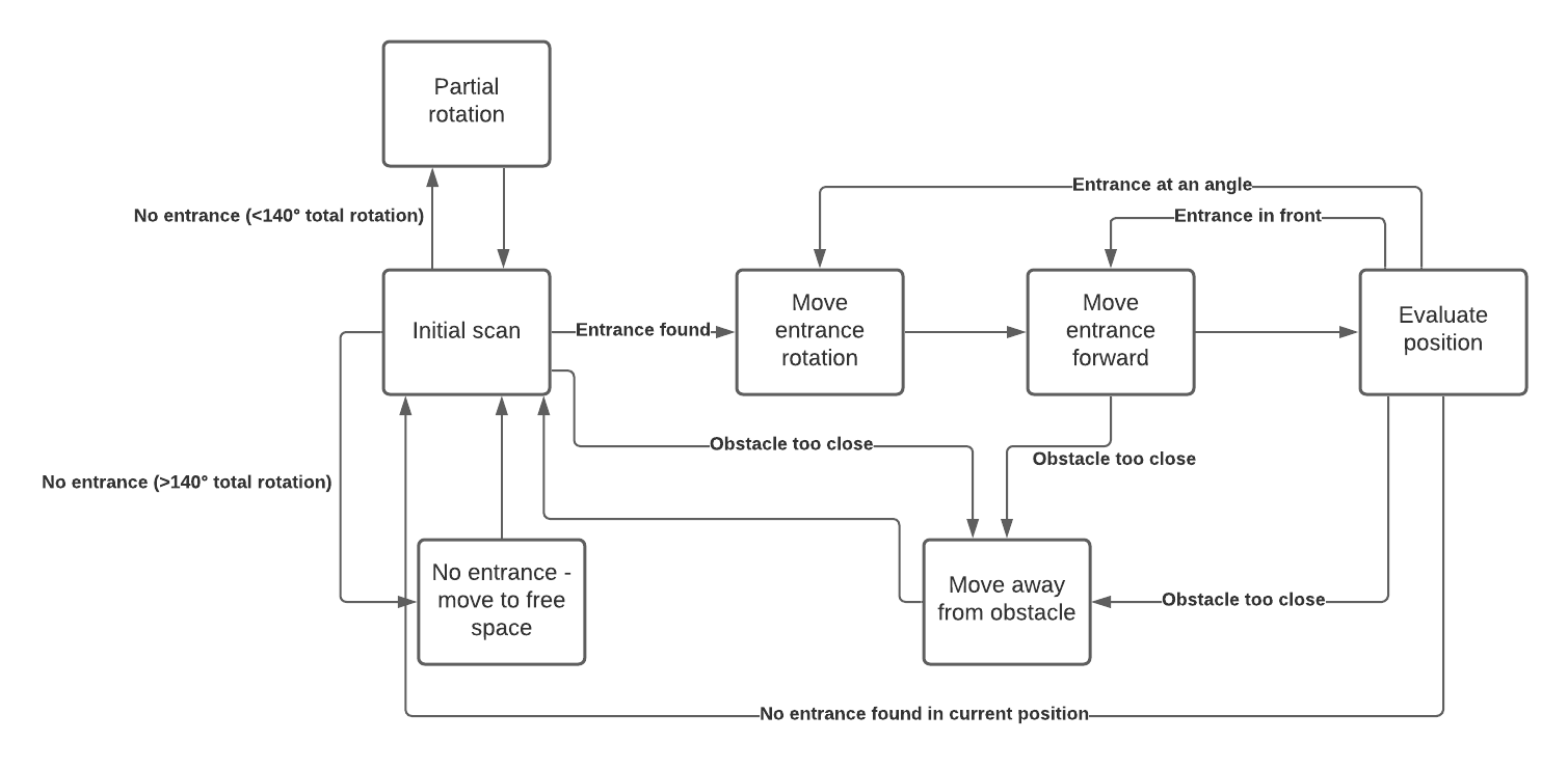
The general structure of the smarter robot is given below. First, an initial scan is performed to find the entrance of the hallway. If an entrance is found, PICO will receive a point where it can move towards via the states 'Move entrance rotation' and 'Move entrance forward'. How the exit is determined is explained in the section 'Line segments and entrance detection'. If no entrance is detected, PICO will perform a partial rotation of 30 degrees and start scanning again for an exit. When no entrance is found after performing a full scan of the room, it is likely that the entrance is not visible from the current position of the robot. In the state 'No entrance - move to free space', PICO will move forward towards a new spot and try to locate the entrance at the new position.
If an entrance is detected, PICO will rotate until it faces the entrance and move forward. Since it should be taken into account that PICO might indicate an exit where there is none, an evaluation is performed after a few steps. If the entrance is still in front of the robot, PICO keeps moving forward. If the entrance is not directly in front of PICO due to drift, a rotation is performed before moving forward again. It could be possible that a false exit was detected before or PICO has drifted too much to still find the exit. Then a new full room scan is performed.
PICO should avoid running into obstacles including static and dynamic objects. Therefore a function is designed that maintains a certain distance from all obstacles which is called 'bubbleRobot'. When PICO is too close to an obstacle, it will stop and move in the opposite direction. To avoid running into the obstacle again, the movement away from the obstacle is more than the distance to leave the bubble. When the robot has moved away from the obstacle, it will reevaluate its position.
Line Segmentation
Line detection from data points is a fundamental task in many fields of science and engineering. In the case of the mobile robot, line detection algorithm is the underlying cornerstone for feature extraction, such as wall, corner and entrance detection.
PICO acquires its data points via the laser range finder (LRF). The LRF outputs in one sweep 1000 data points, consisting of the distances ([math]\displaystyle{ r }[/math]) corresponding to particular angles ([math]\displaystyle{ \theta }[/math]), as shown in Figure 1. The first data point is at -2 rad and the last data point is at +2 rad. Invalid data points above 10 m and below 0.01 m are filtered out. The data points are then converted from polar coordinates to cartesian coordinates using the following geometric equations: [math]\displaystyle{ 2x \times 4y \div 6z + 8 - \frac {y}{z^2} = 0 }[/math] [math]\displaystyle{ y = r_i*\sin(-2 + \Delta \theta * i) }[/math]

Entrance Detection
Laser data can be quite noisy, which can result in a false detection of the entrance when just using one scan as input. Therefore a few scans after each other are performed. The median of the estimated angle and distance towards the entrance is used to plan the motion.
