PRE2019 3 Group4 SolidWorks Casing: Difference between revisions
No edit summary |
No edit summary |
||
| (8 intermediate revisions by the same user not shown) | |||
| Line 1: | Line 1: | ||
The casing that will be used for the final design has been made in SolidWorks. Due to the broad available literature regarding SolidWorks, this was the most viable option. The final design, and its subparts (case and lid), are depicted in the images on this page. | The casing that will be used for the final design has been made in SolidWorks. Due to the broad available literature regarding SolidWorks, this was the most viable option. The final design, and its subparts (case and lid), are depicted in the images on this page. | ||
In the final design, the dimensions L x W x H are much larger than the estimated dimensions for the crude approximation, namely being | In the final design, the dimensions L x W x H are much larger than the estimated dimensions for the crude approximation, namely being 271 x 160 x 76 mm. For the first sketch these dimensions were estimated on 120 x 40 x 50 mm. These larger dimensions are due to the fact that an external power supply has to be added that can deliver 5 V and 7 A. This large current is needed to drive the solenoids and to keep them pressed when they are operated by the user. Also the solenoids take much more place than estimated to reduce the total cost, since the tiny braille cells are quite expensive due to patents. If this product would be launched on the market, a more viable option to these large buttons has to be deliberated upon with a trade-off analysis between the largeness of a braille cell and the total cost associated with it, such that the product will still be available for a very broad public. | ||
For the casing itself, the left side features a small rectangular cutout where the on/off button will be placed. For the on/off button the decision has been made to apply a toggleable switch, such that it can only be interpreted as on or off. With its position on the top of the left side of the case, it can be felt immediately when the product is given to a blind person. Beneath this on/off button the external Meanwell 5 V 7 A power supply will be located. On the front of the casing there is a rectangular cutout for the input of the Meanwell power supply, namely being 230 V mains voltage. When all the connections are made for the 230 V mains voltage and the internal 5 V and 7 A, it is important to properly seal this cutout to avoid unnecessary risk for the user. The logo, showing the brand name 'Braillearn', is also depicted on the front side, with its braille-equivalent name placed directly underneath it. With the logo spanning over the entire front side of the casing, it is very easy to make a stylish product and to create a brand. Furthermore, on the right side of the case is a small rectangular cutout for the RPi voltage input for linking the RPi to ones computer via a micro-USB cable. Also the jack plug input for the external headphones is placed beneath the large circular cutout for the speaker, such that all sound-related items are on one side of the design for simplicity. | |||
Regarding the lid of the casing, there are two large circular cutouts that will feature the reset and next button of the design. With the reset button placed on the left and the next button on the right, minor inconveniences can be avoided, since 'next' is most of the time associated with a button the furthest to the right and 'reset' vice versa. In the middle of the lid are two small rectangular cutouts that will feature the two buttons to select the mode of the Braillearn. These modes are described in more detail in the implementation section of the main page. With these small cutouts placed in the center of the lid, it is easy to locate the small buttons on the entire lid. At last 12 circular cutouts are located symmetrically around the origin, which will feature the example braille (left) and the input braille (right) keyboards. | Regarding the lid of the casing, there are two large circular cutouts that will feature the reset and next button of the design. With the reset button placed on the left and the next button on the right, minor inconveniences can be avoided, since 'next' is most of the time associated with a button the furthest to the right and 'reset' vice versa. In the middle of the lid are two small rectangular cutouts that will feature the two buttons to select the mode of the Braillearn. These modes are described in more detail in the implementation section of the main page. With these small cutouts placed in the center of the lid, it is easy to locate the small buttons on the entire lid. At last 12 circular cutouts are located symmetrically around the origin, which will feature the example braille (left) and the input braille (right) keyboards. With the input placed on the right side together with the next button, it is possible to quickly type the input that is needed and to submit this specific input afterwards. | ||
After deliberation with the 3D printing contact, several changes had been made to the design. For example to increase the ease of the printing process, the angles at the bottom of the casing were changed to 45 degrees for the best printing result. Next to that, multiple inner layer walls have been added to increase the stability of the casing and to keep separate component sections apart from each other in the casing. At last, the add-ons that will indicate the braille read and input cells have been moved to a separate SolidWorks file to further increase the stability of the printing process, such that the printer can print on a large plane instead of two small area planes. These add-ons will be glued to the final design after the 3D printing process. | |||
The SolidWorks design files and screenshots are given in the following Google Drive map. [https://drive.google.com/open?id=1oMY24jnGP5E1mfy4_isxYkMmuCt8Lmx1] | |||
[[file:Case_Left.png|500px|thumb|The left side of the casing that will be used for the final product]] | [[file:Case_Left.png|500px|thumb|The left side of the casing that will be used for the final product]] | ||
[[file:Case_Right.png|500px|thumb|The right side of the casing that will be used for the final product]] | [[file:Case_Right.png|500px|thumb|The right side of the casing that will be used for the final product]] | ||
[[file:Case_Front.png|500px|thumb|The front side of the casing that will be used for the final product]] | |||
[[file:Case_Top.png|500px|thumb|The top of the casing that will be used for the final product]] | [[file:Case_Top.png|500px|thumb|The top of the casing that will be used for the final product]] | ||
[[file:Lid_Top.png|500px|thumb|The top of the lid that will be used for the final product]] | [[file:Lid_Top.png|500px|thumb|The top of the lid that will be used for the final product]] | ||
[[file:Lid_Top_Add_On.png|500px|thumb|The add-ons for the top of the lid that will be used for the final product]] | |||
[[file:Case_Final.png|500px|thumb|The casing in total that will be used for the final product]] | [[file:Case_Final.png|500px|thumb|The casing in total that will be used for the final product]] | ||
[[file:Case_Final_2.png|500px|thumb|The casing in total that will be used for the final product]] | [[file:Case_Final_2.png|500px|thumb|The casing in total that will be used for the final product]] | ||
Latest revision as of 12:35, 12 March 2020
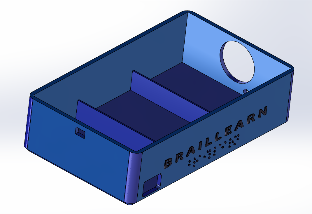
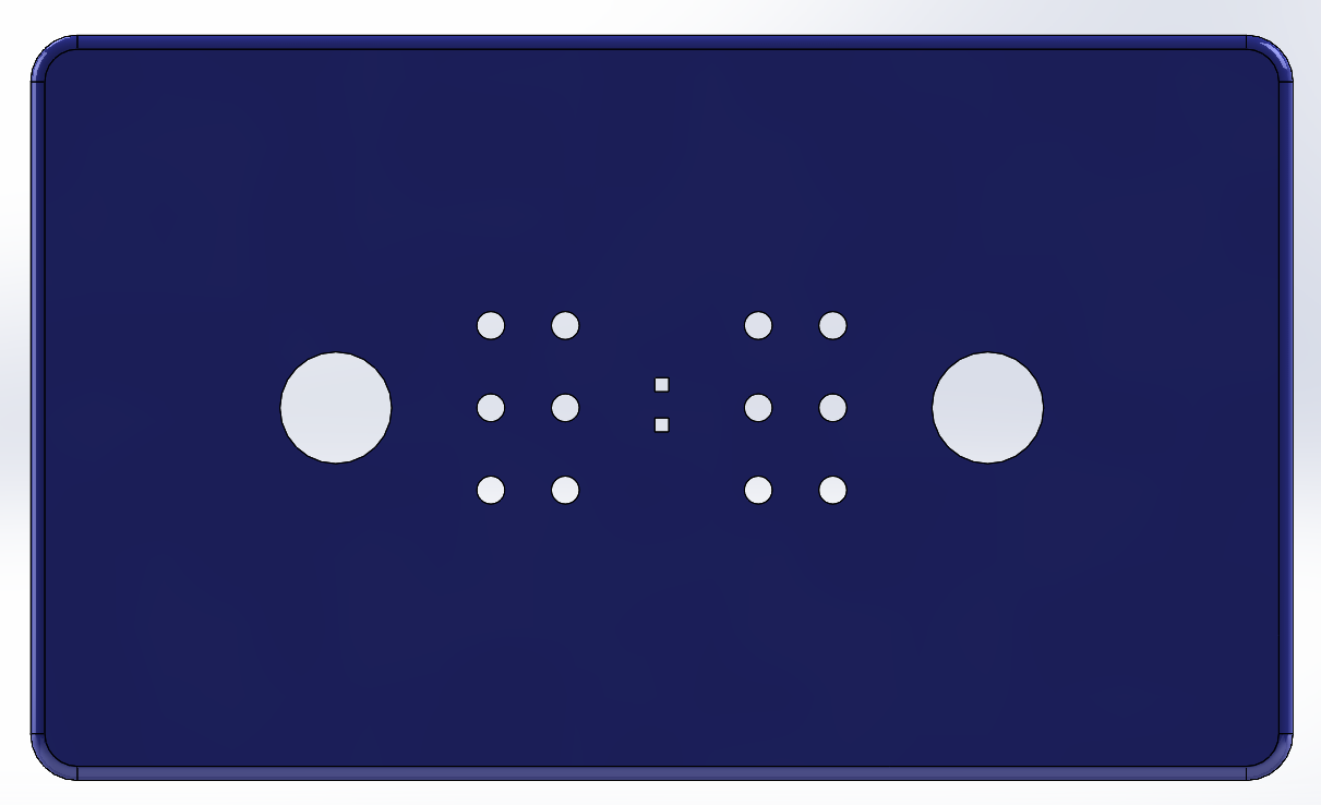
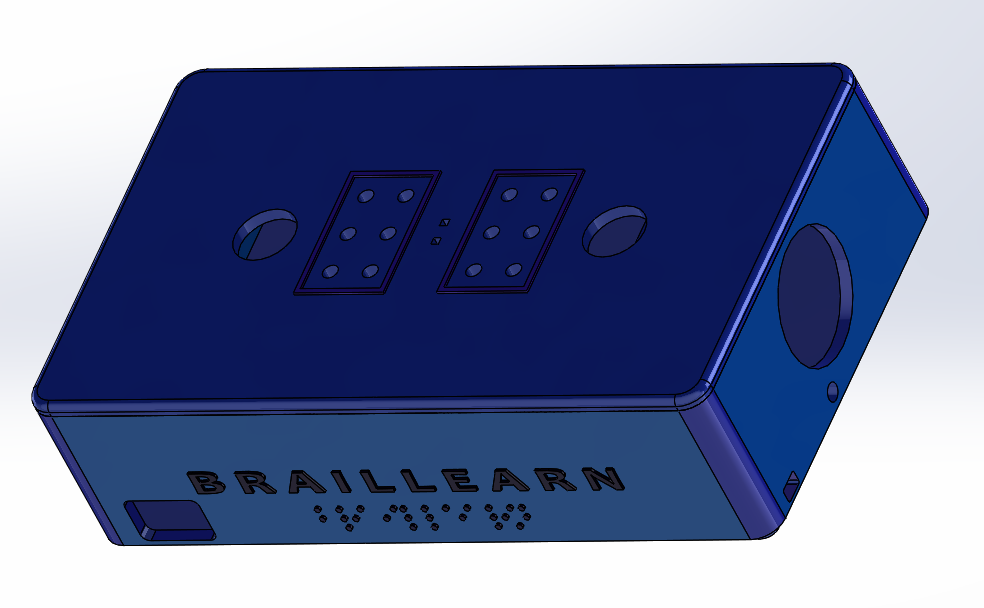
The casing that will be used for the final design has been made in SolidWorks. Due to the broad available literature regarding SolidWorks, this was the most viable option. The final design, and its subparts (case and lid), are depicted in the images on this page.
In the final design, the dimensions L x W x H are much larger than the estimated dimensions for the crude approximation, namely being 271 x 160 x 76 mm. For the first sketch these dimensions were estimated on 120 x 40 x 50 mm. These larger dimensions are due to the fact that an external power supply has to be added that can deliver 5 V and 7 A. This large current is needed to drive the solenoids and to keep them pressed when they are operated by the user. Also the solenoids take much more place than estimated to reduce the total cost, since the tiny braille cells are quite expensive due to patents. If this product would be launched on the market, a more viable option to these large buttons has to be deliberated upon with a trade-off analysis between the largeness of a braille cell and the total cost associated with it, such that the product will still be available for a very broad public.
For the casing itself, the left side features a small rectangular cutout where the on/off button will be placed. For the on/off button the decision has been made to apply a toggleable switch, such that it can only be interpreted as on or off. With its position on the top of the left side of the case, it can be felt immediately when the product is given to a blind person. Beneath this on/off button the external Meanwell 5 V 7 A power supply will be located. On the front of the casing there is a rectangular cutout for the input of the Meanwell power supply, namely being 230 V mains voltage. When all the connections are made for the 230 V mains voltage and the internal 5 V and 7 A, it is important to properly seal this cutout to avoid unnecessary risk for the user. The logo, showing the brand name 'Braillearn', is also depicted on the front side, with its braille-equivalent name placed directly underneath it. With the logo spanning over the entire front side of the casing, it is very easy to make a stylish product and to create a brand. Furthermore, on the right side of the case is a small rectangular cutout for the RPi voltage input for linking the RPi to ones computer via a micro-USB cable. Also the jack plug input for the external headphones is placed beneath the large circular cutout for the speaker, such that all sound-related items are on one side of the design for simplicity.
Regarding the lid of the casing, there are two large circular cutouts that will feature the reset and next button of the design. With the reset button placed on the left and the next button on the right, minor inconveniences can be avoided, since 'next' is most of the time associated with a button the furthest to the right and 'reset' vice versa. In the middle of the lid are two small rectangular cutouts that will feature the two buttons to select the mode of the Braillearn. These modes are described in more detail in the implementation section of the main page. With these small cutouts placed in the center of the lid, it is easy to locate the small buttons on the entire lid. At last 12 circular cutouts are located symmetrically around the origin, which will feature the example braille (left) and the input braille (right) keyboards. With the input placed on the right side together with the next button, it is possible to quickly type the input that is needed and to submit this specific input afterwards.
After deliberation with the 3D printing contact, several changes had been made to the design. For example to increase the ease of the printing process, the angles at the bottom of the casing were changed to 45 degrees for the best printing result. Next to that, multiple inner layer walls have been added to increase the stability of the casing and to keep separate component sections apart from each other in the casing. At last, the add-ons that will indicate the braille read and input cells have been moved to a separate SolidWorks file to further increase the stability of the printing process, such that the printer can print on a large plane instead of two small area planes. These add-ons will be glued to the final design after the 3D printing process.
The SolidWorks design files and screenshots are given in the following Google Drive map. [1]


