Viotar/Proof of concept: Difference between revisions
Jump to navigation
Jump to search
| (7 intermediate revisions by one other user not shown) | |||
| Line 37: | Line 37: | ||
| style="border:2px solid #00FF33; background-color:#CCFF99"| | | style="border:2px solid #00FF33; background-color:#CCFF99"| | ||
==The final | ==The final assembly== | ||
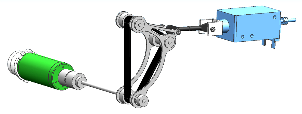
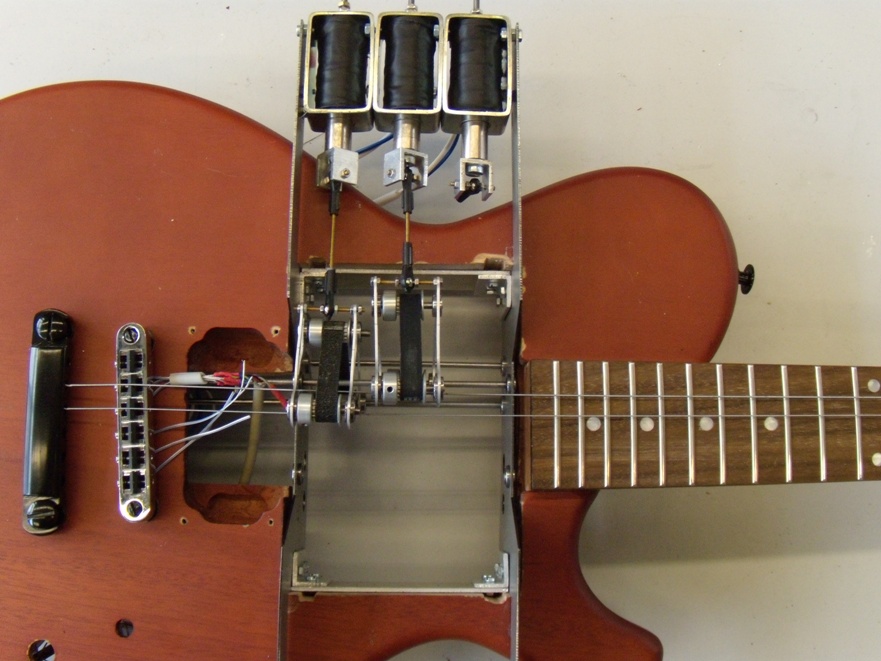
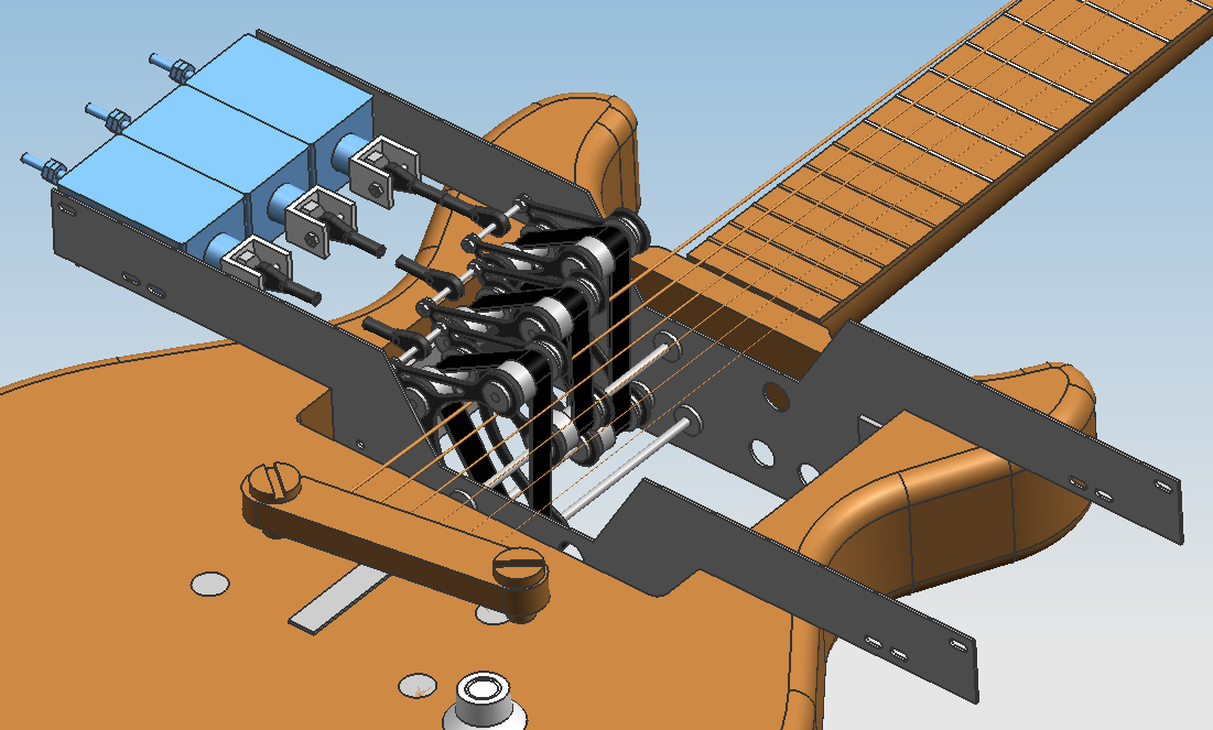
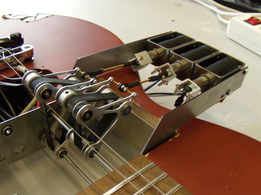
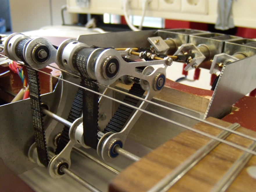
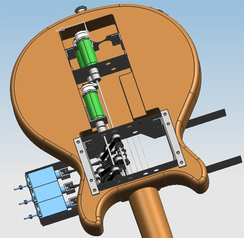
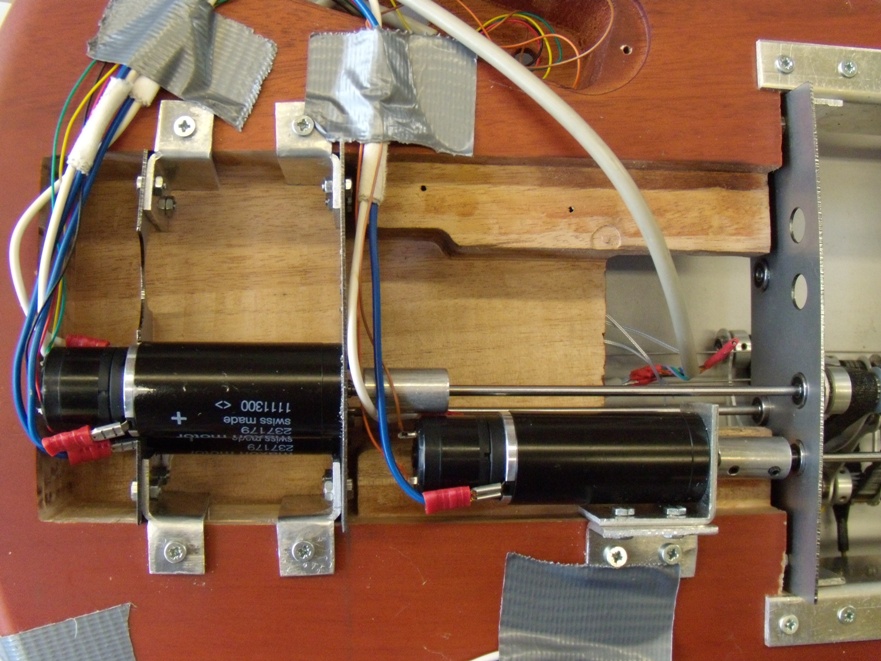
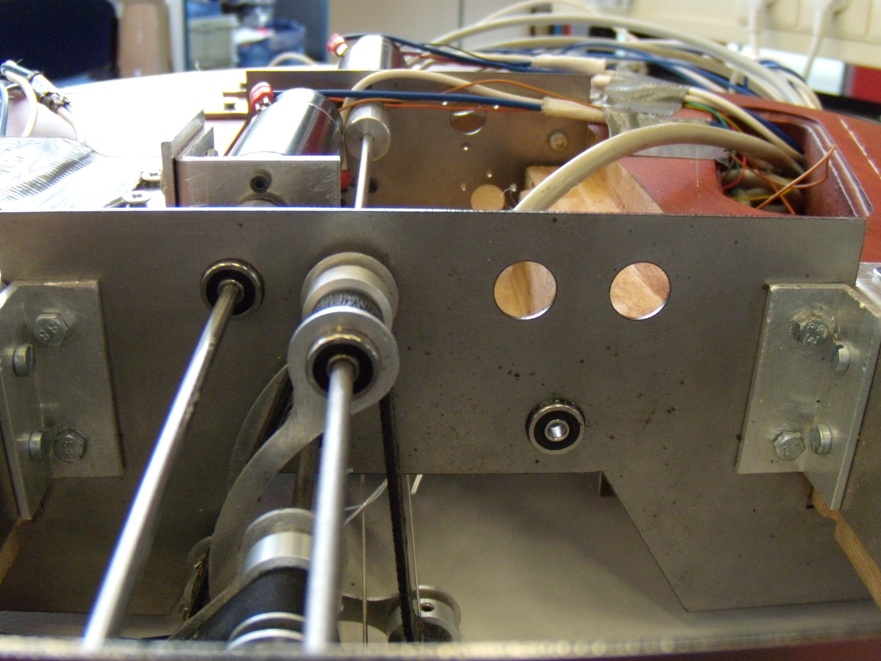
After the Viotar was completely designed in NX5 the actual ordering of the parts and the assembly was done. The design process is described on the Hardware design page, this page will show the final results after the assembly of the parts. Drawing every part and making the assembly in NX5 did take a lot of time and effort, but during the actual making of the Viotar this time and effort definitely helped us a lot. Because the assembly was already made in NX5 all the parts did fit perfectly when they arrived and making the Viotar in real life was quite easy. The figures below show the design of the complete assembly as it was made in NX5 and photographs of the actual assembly. From these photographs it can easily be seen that they are exactly the same, no changes had to be made in order for the assembly to fit. | |||
{| align=center padding=0 cellspacing=0 style="background:# | |||
{| align=center padding=0 cellspacing=0 style="background:#CCFF99" width="1215px" | |||
|- | |- | ||
| style="font-size:85%; border:1px solid #cccccc; padding:3px 3px 0px 3px" | | | style="font-size:85%; border:1px solid #cccccc; padding:3px 3px 0px 3px" | | ||
[[File:Design06img06.jpg|800px]] [[File:Viotar_001.jpg|400px]] | [[File:Design06img06.jpg|800px]] [[File:Viotar_001.jpg|400px]]<br/> | ||
Left: | Left: The complete assembly for the actuation of one string.<br/>Right: A top view of the Viotar completely assembled for actuating two string.<br/><br/> | ||
[[File:Design06img01.jpg|400px]] [[File:Viotar_002.jpg|400px]] [[File:Viotar_003.jpg|400px]]<br/> | |||
Left: The Solenoids and belts as they were designed in NX5.<br/>Middle and Right: The actual assembly of the solenoids and bowing belts.<br/><br/> | |||
[[File:Design06img02.jpg|400px]] [[File:Viotar_005.jpg|400px]] [[File:Viotar_006.jpg|400px]]<br/> | |||
Left: The bottom side of the Viotar, as it whas designed in NX5.<br/>Middle and Right: The bottom side of the Viotar when it whas actually assembled. | |||
|- | |- | ||
|} | |} | ||
<br/> | |||
One thing that probably draws the attention is the fact that the photographs only show the assembly for actuating two strings. This was not the intention but the funds that were available did not allow us to make the actuation for all six strings. The fact that we managed to assemble the Viotar exactly as we made it in NX5 does prove that it is technically possible to make the assembly where all six strings are actuated, only more funds have to be raised in order to do so. | |||
==Proof of concept== | |||
Latest revision as of 11:00, 28 March 2011
|
