PRE2018 4 Group6: Difference between revisions
| (68 intermediate revisions by 5 users not shown) | |||
| Line 28: | Line 28: | ||
=== Minutes === | === Minutes === | ||
Throughout the course the group will have official meetings. A summary (minute) of what has been said/achieved in every meeting will be made. These summaries can be found | Throughout the course the group will have official meetings. A summary (minute) of what has been said/achieved in every meeting will be made. These summaries can be found | ||
[[PRE2018_4_Group6_minutes|here]]. | [[PRE2018_4_Group6_minutes|here]]. This has been discontinued due to lazyness and for brevity. | ||
=== Agendas === | === Agendas === | ||
| Line 71: | Line 71: | ||
===Enterprise=== | ===Enterprise=== | ||
Rijkswaterstaat is a governmental group which is responsible for the maintenance of the roads. Roads are constructed and maintained from the taxes that are paid by Dutch citizens. For them it is necessary that the implementation of a smart is cost efficient. It should not have to cost more than it has to. Implementing an expensive smart road over a short distance is not very effective, and implementing one over a too long distance just gets very expensive. The right division has to be found. They also need the roads to be as simple as possible, for this would simplify the maintenance and construction of the roads (and its elements). The technology should not be too hard to maintain. | Rijkswaterstaat is a governmental group which is responsible for the maintenance of the roads. Roads are constructed and maintained from the taxes that are paid by Dutch citizens. For them it is necessary that the implementation of a smart road is cost efficient. It should not have to cost more than it has to. Implementing an expensive smart road over a short distance is not very effective, and implementing one over a too long distance just gets very expensive. The right division has to be found. They also need the roads to be as simple as possible, for this would simplify the maintenance and construction of the roads (and its elements). The technology should not be too hard to maintain. | ||
A different enterprise stakeholder are transport companies. These include both cargo transport, as well as public transport (e.g. buses & taxi's). The time spent on highways at which the traffic flows smoothly is minimized. In order to maximize their revenue, these enterprise therefore also require a smooth traffic flow on highways. | A different enterprise stakeholder are transport companies. These include both cargo transport, as well as public transport (e.g. buses & taxi's). The time spent on highways at which the traffic flows smoothly is minimized. In order to maximize their revenue, these enterprise therefore also require a smooth traffic flow on highways. | ||
| Line 79: | Line 79: | ||
The requirements from all of the stakeholders impose constraints on the design of the system which can turn the regular highway into an actual smart road. All of the user stakeholders, the environmental organizations and transport companies do not really impose any constraints on the design aside from the fact that road should not become less safe. The actual constraints arise from the government and Rijkswaterstaat. | The requirements from all of the stakeholders impose constraints on the design of the system which can turn the regular highway into an actual smart road. All of the user stakeholders, the environmental organizations and transport companies do not really impose any constraints on the design aside from the fact that road should not become less safe. The actual constraints arise from the government and Rijkswaterstaat. | ||
=== | ===The law=== | ||
* The Wegenverkeerswet regulates the traffic and infrastructure of the Netherlands. This law states that the minimum acceptable speed for motorized vehicles that would like to use the highway is 60 km/h, whereas the maximum acceptable speed is 130 km/h. The design we have chosen dynamically moves the barriers over the road. It would look like a standing wave on the highway, instead it should just be look upon as a barrier moving machines that picks up and places concrete barriers, but now it is fully automized. The propagation speed of the barrier should not be higher than the maximum speed of the slowest moving vehicles on the highways. It should therefore never exceed 60 km/h. | * The Wegenverkeerswet regulates the traffic and infrastructure of the Netherlands. This law states that the minimum acceptable speed for motorized vehicles that would like to use the highway is 60 km/h, whereas the maximum acceptable speed is 130 km/h. The design we have chosen dynamically moves the barriers over the road. It would look like a standing wave on the highway, instead it should just be look upon as a barrier moving machines that picks up and places concrete barriers, but now it is fully automized. The propagation speed of the barrier should not be higher than the maximum speed of the slowest moving vehicles on the highways. It should therefore never exceed 60 km/h. | ||
The speed at which the barriers changes from lane to lane (perpendicular to the direction in which the highway is traversed) mustn't be too high. Drivers of vehicles could easily get scared with a barrier moving towards them with a high speed, which causes dangerous situations. This transition should happen smoothly. | The speed at which the barriers changes from lane to lane (perpendicular to the direction in which the highway is traversed) mustn't be too high. Drivers of vehicles could easily get scared with a barrier moving towards them with a high speed, which causes dangerous situations. This transition should happen smoothly. | ||
| Line 85: | Line 85: | ||
*The second constraint arise from article 14 of the Wegenverkeerswet (https://wetten.overheid.nl/BWBR0001948/2017-09-01). This article states that each highway in the Netherlands should have a shoulder (berm). this could cause problem if extra lanes are added to solve the congestion problem, since in some cases there is not any space left for a shoulder. This constraint is pretty much always adhered to with the design we chose. The system divides the highway into two road going in opposite directions. No extra lanes would be added in this case, and therefore there will always be a shoulder at each side of the highway. This shoulder is, like all other roads, located right of most right lane for each direction of the highway. | *The second constraint arise from article 14 of the Wegenverkeerswet (https://wetten.overheid.nl/BWBR0001948/2017-09-01). This article states that each highway in the Netherlands should have a shoulder (berm). this could cause problem if extra lanes are added to solve the congestion problem, since in some cases there is not any space left for a shoulder. This constraint is pretty much always adhered to with the design we chose. The system divides the highway into two road going in opposite directions. No extra lanes would be added in this case, and therefore there will always be a shoulder at each side of the highway. This shoulder is, like all other roads, located right of most right lane for each direction of the highway. | ||
=== | ===Rijkswaterstaat=== | ||
Aside from the constraints that result from the requirements of the USE stakeholders we came up with, an actual representative of one of the stakeholders can give feedback and perhaps impose more constraints which we work with. | Aside from the constraints that result from the requirements of the USE stakeholders we came up with, an actual representative of one of the stakeholders can give feedback and perhaps impose more constraints which we work with. | ||
| Line 91: | Line 91: | ||
These constraints will get clearer after the interview with Rijkswaterstaat. | These constraints will get clearer after the interview with Rijkswaterstaat. | ||
=== | ===The location=== | ||
The location that has been used for our concept is the road between Boxtel and Best on the A2 in the Netherlands. This road is in agreement with our constraints. This is because of the amount of car driving with the right distribution. Also the amount of lanes and distance of the route aare in agreement. The length of 13.8 km makes it perfect for the change of roads with the lanes. The highway can be seen in the route [http://www.google.com/maps/dir/51.5139228,5.4033612/51.618149,5.3169475/@51.5644903,5.2076401,10.59z/data=!4m2!4m1!3e0 here]. | The location that has been used for our concept is the road between Boxtel and Best on the A2 in the Netherlands. This road is in agreement with our constraints. This is because of the amount of car driving with the right distribution. Also the amount of lanes and distance of the route aare in agreement. The length of 13.8 km makes it perfect for the change of roads with the lanes. The highway can be seen in the route [http://www.google.com/maps/dir/51.5139228,5.4033612/51.618149,5.3169475/@51.5644903,5.2076401,10.59z/data=!4m2!4m1!3e0 here]. | ||
| Line 182: | Line 182: | ||
Flexible lines are a promising solution. It is definetly one of the better solutions against traffic congestion, but it comes with its difficulties. If a solution to these difficulties has been found it will surely be the better solution out of all the ones previously mentioned. | Flexible lines are a promising solution. It is definetly one of the better solutions against traffic congestion, but it comes with its difficulties. If a solution to these difficulties has been found it will surely be the better solution out of all the ones previously mentioned. | ||
== Data Analysis == | |||
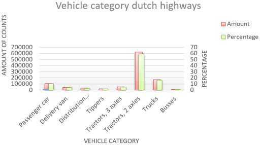
The data of the intensity and Average speed is received from the [https://dexter.ndwcloud.nu/opendata Site] of 'Nationale Databank Wegverkeersgegevens'. The data about the vehicle category is received from the [http://www.emissieregistratie.nl/erpubliek/documenten/Lucht%20(Air)/Verkeer%20en%20Vervoer%20(Transport)/Wegverkeer/TNO%20(2013)%20Beladingsgraden%20vrachtverkeer%20WiM.pdf site] of TNO. The data has been analysed and processed in the following file: [[File:Speed_Intensity_Category.zip]]. | |||
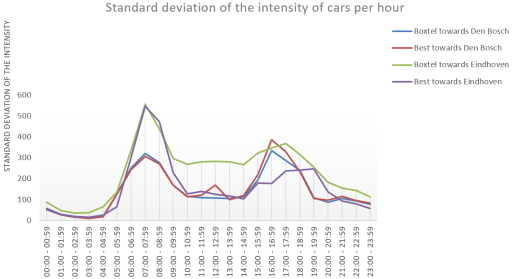
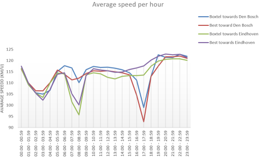
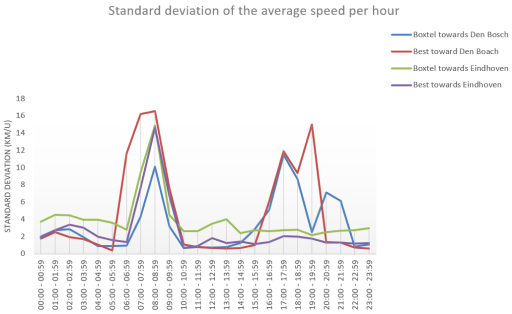
The data from four different places has been requested. Namely two in Best, one towards Den Bosch (51.5190323;5.3982506) and towards Eindhoven(51.5189078;5.3981406), and two in Boxtel, one towards Den Bosch (51.6182637;5.3169165) and towards Eindhoven (51.6180882;5.3167447). | |||
In these four places, all velocities and intensities has been searched up and selected per month. 12 Months in total beginning from 22-5-2018 till 21-5-2019. These data sets represent each Monday till Friday excluding the holidays. Therefor these data sets represents the same kind of information and is more reliable for our modelling. | |||
From these 12 months both the average is calculated as the standard deviation per hour. These are then plotted per measurement place over the hours. This has been done for the Intensity and the average speed. For the length of the cars passing the highway another method has been used. The results can be seen down below. | |||
===Intensity=== | |||
The intensity is plotted per hour for all four measurements points. Also the standard deviation is calculated. | |||
[[File:Intensity_of_cars_per_hour.png]] | |||
[[File:Standard_deviation_of_the_intensity_of_cars_per_hour.png]] | |||
===Average speed=== | |||
The average speed is also plotted per hour with the standard deviation. | |||
[[File:Average_speed_per_hour.png]] | |||
[[File:Standard_deviation_of_the_average_speed_per_hour.png]] | |||
===Vehicle category=== | |||
The kind of vehicles passing by is determined apart from the intensities, but both data sets give a representation of the highways in The Netherlands. | |||
[[File:Vehicle_category.png]] | |||
An additional vital piece of data that has been required is the theoretical value of the critical density. This concept is further explained in the section about the mathematical model and holds a value of approximately 131 vehicles per lane mile (MIT). | |||
==Survey Analysis== | |||
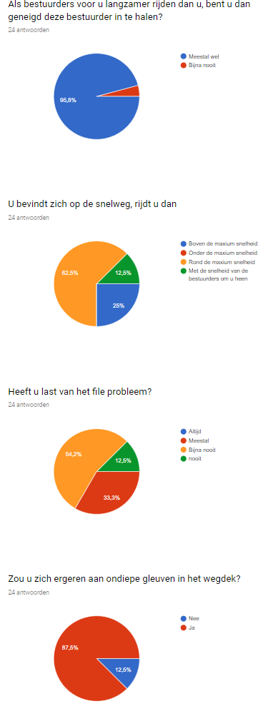
In order to get a little bit more familiar with the users we sent out a survey. This survey allows us to determine the relevance of our selected problem. We knew beforehand what kind of answers we were going to receive, as we are also part of the user stakeholders. The questions of the survey are rather trivial and they are answered by 24 recipients. One thing to note beforehand is that 24 recipients is not very representative of all the inhabitants of the Netherlands. The survey, and answers to the questions, in Dutch, are provided below. | |||
[[File:Knipsel.PNG]] | |||
Even though the amount of recipients of the survey is quite low, there is still some important information that can be extracted from the survey. As we expected, almost everyone gets frustrated from traffic congestion caused by slower moving vehicles. All of the recipients try to minimize congestion be driving at at least the maximum speed. Occasionally there are is a couple that follows the behaviour of other drivers on the road. This also has the effect to reduce congestion, provided that this speed is not substantially lower than the maximum speed. To our surprise, over half of the recipients has answered that they rarely deal with traffic jams due to congestion. A third has answered that traffic congestion often is a problem for them. We think that this remarkable result is a result of the small group of recipients of the survey. Lastly, almost all of the recipients agreed that small grooves in the road would be pretty annoying. This latter results has been used when designing the smart road, as we needed to keep the user satisfied. | |||
==The concept== | ==The concept== | ||
During the meeting on 17-05, we eliminated some potential solutions for the congestion problem. Neither carpool lanes, nor the stationary road barrier seemed like the most optimal solution for this problem. Instead, the latter two out of four have been chosen, | During the meeting on 17-05, we eliminated some potential solutions for the congestion problem. Neither carpool lanes, nor the stationary road barrier seemed like the most optimal solution for this problem. Instead, the latter two out of four have been chosen, the best of both solutions are combined to create what we believe will be the most optimal way to decrease traffic congestion. | ||
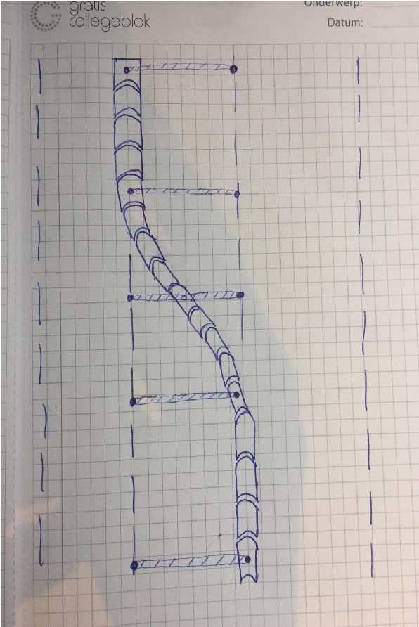
The design combines the concepts of the flexible lines and the movable barrier system. One flaw that was present in the flexible lines concept was how to actually draw the lines between the lanes. We figured that implementing the concrete barriers, the same ones as from the movable barrier system | The design combines the concepts of the flexible lines and the movable barrier system. One flaw that was present in the flexible lines concept was how to actually draw the lines between the lanes. We figured that implementing the concrete barriers, the same ones as from the movable barrier system could work out quite well. This would also mean that the big machine that moves the barriers would be obsolete. We wanted the barriers to move independently. The barriers, again with dimensions like such[https://imgur.com/a/g60vok1], would be placed on some sort of rails in between the lanes. A visualization of the concept can be found below. | ||
[[File:Schets slang.jpeg]] | [[File:Schets slang.jpeg]] | ||
| Line 193: | Line 228: | ||
Some parts of the barrier (pivots), would be able to move horizontally over the road, which would cause the other barriers, attached to these pivot barriers, to follow them. The barriers would sort of move like a snake in between the roads. After the pivot barriers move horizontally and have reached their destination, the barriers lock in place. | Some parts of the barrier (pivots), would be able to move horizontally over the road, which would cause the other barriers, attached to these pivot barriers, to follow them. The barriers would sort of move like a snake in between the roads. After the pivot barriers move horizontally and have reached their destination, the barriers lock in place. | ||
A concept like this is very dynamical, in the sense that it can be applied according to the situations on the road. Its application is not just limited to peak hours, but it can even be used to reduce congestion outside of them | A concept like this is very dynamical, in the sense that it can be applied according to the situations on the road. Its application is not just limited to peak hours, but it can even be used to reduce congestion outside of them when applied timely. It takes the best of both of our concepts and combines them to create the most optimal solution. It is very flexible, and it can be used much faster, and thus also more efficient than the big machine that would independently move the barriers, at a rather slow pace. | ||
This concept also comes with its constraints: | This concept also comes with its constraints: | ||
* The number of lanes for which this concept can be applied is at least 3. In this case it would only have one extra lane to divide between both sides of the road. The distribution of the lanes will be more optimal if there are more roads available which the system can be used. | * The number of lanes for which this concept can be applied is at least 3. In this case, it would only have one extra lane to divide between both sides of the road. The distribution of the lanes will be more optimal if there are more roads available which the system can be used. | ||
* The system needs to be powered. The concrete barriers | * The system needs to be powered. The concrete barriers cannot move by themselves. Since we no longer want them to be moved by a big machine, they need to be powered, and some movement mechanism has to be come up with. | ||
* The speed at which the barriers move must be below maximal value. When the speed at which the barriers move is too fast, other vehicles can be cut off, which could cause dangerous situations. | * The speed at which the barriers move must be below maximal value. When the speed at which the barriers move is too fast, other vehicles can be cut off, which could cause dangerous situations. | ||
*The barrier needs to be able to withstand the impulse of a vehicle that impacts on it. This means that it should remain standing, stationary and undamaged after potential collisions. | |||
===Design of the barrier blocks=== | |||
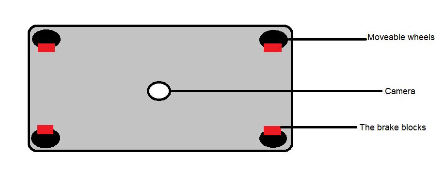
The moveable barrier will be divided into segments of concrete blocks (these blocks will have a width of 0.5m, the height of 0.99m and length 0.5m and will have a weight of 680 kg). In order to let the barrier moveable all the segments will be placed on four wheels (each in one corner). Every wheel will be mounted with brakes. These brakes need to be strong enough such that the barrier won’t move if a vehicle collided with the barrier. These brakes will prevent the barrier from moving when they shouldn’t move (in the case of a collision or a malfunction of the system). In order to keep the segments moving to the correct position, the motorised segments will have a camera. With the use of the camera the road will be scanned for recognised points (which are in this case the white stripes of the lanes). With the use of the cameras and the white strips, the segments are calibrated such that will be placed at the correct position on the road. In the figure below a bottom view of a random segment is showed. | |||
[[File:Bottom_view.jpeg]] | |||
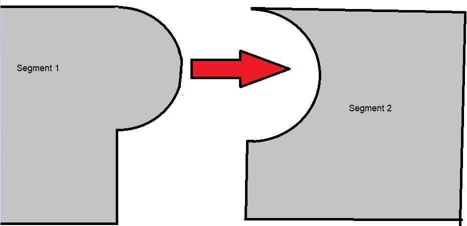
In order to let the barrier move like a snake or sling some of the segments will be mounted with a motor. Not every segment will be motorised (this is in order to keep the cost down). All the segments will be grouped into groups of 15, not motorised concrete blocks and 2 motorised blocks. The motorised segments will be placed at the front and the end of the group. The segments will be connected with each other in two ways. Firstly, every segment will have at on side a spherical fork and at the other and a bowl in which the spherical fork is placed. This coupling system makes that the barrier can move as a uniform sling. The coupling system can be seen in the figure below. | |||
[[File:Coupling system.jpeg]] | |||
The second connecting is made with a mobile cable in which the electrical wire is placed. The cable should be water prove, such that the electrical wire cannot be damaged. The cable should be flexible such that it can move along with the segments. The electrical wire is for powering the electrical motor in the motorised segments and for the cameras at the bottom. The cameras are only placed at the motorised segments (again to keep the cost low and they’re not needed at the no motorised parts). In order to keep the weight of the segments low, the inside of the segments is filled with foam. The electrical parts are placed parallel, such that when one motor fails the other segments keep working. | |||
==Ethics== | ==Ethics== | ||
| Line 203: | Line 250: | ||
In order to take the considerations of the users into account, ethical consideration is made. This is done such that by designing the smart road, the users' constraints and requirements are not forgotten. For the other stakeholders, it is possible to get contact and obtain their requirements and constraints. With the use of the coming ethical consideration (on the basis of the utilism and Kantism) it possible to view what is possible and what isn't possible in other to keep the users in mind. | In order to take the considerations of the users into account, ethical consideration is made. This is done such that by designing the smart road, the users' constraints and requirements are not forgotten. For the other stakeholders, it is possible to get contact and obtain their requirements and constraints. With the use of the coming ethical consideration (on the basis of the utilism and Kantism) it possible to view what is possible and what isn't possible in other to keep the users in mind. | ||
=== | ===Utilitarianism=== | ||
A short recap of utilism: in utilism, it is the goal to perform an action such that it leads to the happiness of most people. A short sidenote: the quality of happiness is also important in the consideration which action to do. In general, a utilitarian would want a road which is designed in such a way that most people who use the road the most often would like and be happy with this road. It is important to look at the most often users of the road, this is because this group of users are having to deal the most with the designed solution (think by these users of transport traffic, commuters etc.). For these stakeholders, it is important that the road user-friendly such that is pleasant to ride the road (no speedbumps or low-quality roads (like the Belgian roads). Secondly, it is important that it is clear how to uses the road (with respect to the designed smart road). If the road is unclear how to use, it would lead to people who get irritated or unhappy with the designed road. A utilitarian would disapprove this because it (in this case) does not lead to the most happiness for the most people. So when designing the smart road and the users are approached by a utilitarian way of thinking, it is important to keep in mind that the most important stakeholders are the users who use the road the most often and that the solution would lead to the most happiness of most people (an important: the most happiness in the group of the most often users). | A short recap of utilism: in utilism, it is the goal to perform an action such that it leads to the happiness of most people. A short sidenote: the quality of happiness is also important in the consideration which action to do. In general, a utilitarian would want a road which is designed in such a way that most people who use the road the most often would like and be happy with this road. It is important to look at the most often users of the road, this is because this group of users are having to deal the most with the designed solution (think by these users of transport traffic, commuters etc.). For these stakeholders, it is important that the road user-friendly such that is pleasant to ride the road (no speedbumps or low-quality roads (like the Belgian roads). Secondly, it is important that it is clear how to uses the road (with respect to the designed smart road). If the road is unclear how to use, it would lead to people who get irritated or unhappy with the designed road. A utilitarian would disapprove this because it (in this case) does not lead to the most happiness for the most people. So when designing the smart road and the users are approached by a utilitarian way of thinking, it is important to keep in mind that the most important stakeholders are the users who use the road the most often and that the solution would lead to the most happiness of most people (an important: the most happiness in the group of the most often users). | ||
| Line 222: | Line 269: | ||
===Conclusion=== | ===Conclusion=== | ||
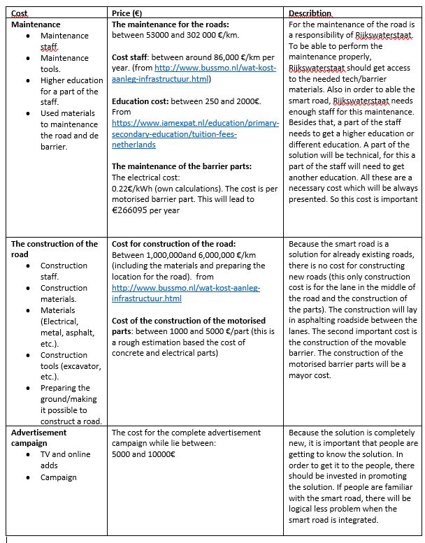
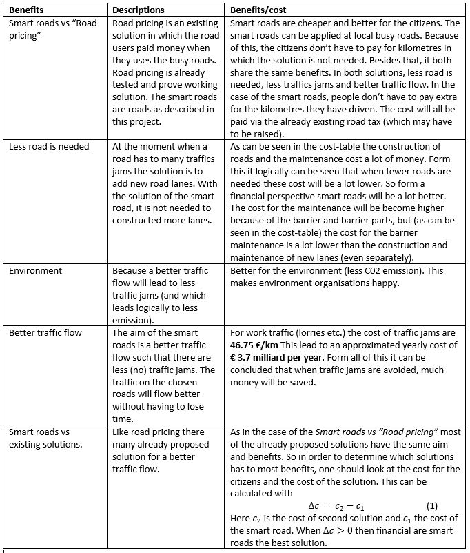
In conclusion of the ethical consideration, it can be concluded that virtue ethics is not useful to take into account by design the smart road. Virtue ethics does not necessarily lead to constraints of requirements form the stakeholders. It will display the virtue of road users like the speeding limit (from https://www.universiteitleiden.nl/binaries/content/assets/customsites/study-abroad-exchange-students/road_traffic_signs_and_regulations_jan_2013_uk.pdf) or how should I use the road. Form this, it won't become clear what the constraints would be, but form virtue ethics it is possible to determine some requirements road users needed. The needs/requirements and constraints of the users can be best explained with the use of the ethical consideration, where the Virtue (only the requirements), Utilitarian and Kant's ethics are combined. Here the Utilitarian is the most important view to use because it is the easiest to use, but also it gives the most disguised requirements and constraints for the user stakeholders. With the use of this ethical consideration, the link between the designed smart road and the road users is made. With this section, the user's stakeholders are explained and given a voice such that these stakeholders aren't ignored and are considered. With this, the designed road will be the best possible solution for all the stakeholders. When the utilitarian and deontological point of view is combined, a complete view of the requirements/constraints forms the user's point of view is given. When using deontology, the second Categorical Imperative is maybe an important rule to keep in mind. Form the first Categorical Imperative some standard constraints (which are still important) or more general rules occur. The second Categorical Imperative actual makes it really sure that users aren't ignored. | In conclusion of the ethical consideration, it can be concluded that virtue ethics is not useful to take into account by design the smart road. Virtue ethics does not necessarily lead to constraints of requirements form the stakeholders. It will display the virtue of road users like the speeding limit (from https://www.universiteitleiden.nl/binaries/content/assets/customsites/study-abroad-exchange-students/road_traffic_signs_and_regulations_jan_2013_uk.pdf) or how should I use the road. Form this, it won't become clear what the constraints would be, but form virtue ethics it is possible to determine some requirements road users needed. The needs/requirements and constraints of the users can be best explained with the use of the ethical consideration, where the Virtue (only the requirements), Utilitarian and Kant's ethics are combined. Here the Utilitarian is the most important view to use because it is the easiest to use, but also it gives the most disguised requirements and constraints for the user stakeholders. With the use of this ethical consideration, the link between the designed smart road and the road users is made. With this section, the user's stakeholders are explained and given a voice such that these stakeholders aren't ignored and are considered. With this, the designed road will be the best possible solution for all the stakeholders. When the utilitarian and deontological point of view is combined, a complete view of the requirements/constraints forms the user's point of view is given. When using deontology, the second Categorical Imperative is maybe an important rule to keep in mind. Form the first Categorical Imperative some standard constraints (which are still important) or more general rules occur. The second Categorical Imperative actual makes it really sure that users aren't ignored. At last a cost-benefit comparison is made which is given: | ||
[[File:Cost_table.JPEG]] | |||
[[File:PRE2018_4_Group6_Benefits-tabl.JPEG]] | |||
==Responsibility== | ==Responsibility== | ||
| Line 230: | Line 281: | ||
==Mathematical model== | ==Mathematical model== | ||
For the mathematical model, the real-life issue is required to be translated into the mathematical language. We would prefer to have the model to be as simple as possible. This could be accomplished by viewing the propagation direction the cars on the road to be represented by a piece of the real number line. Define the whole set of real numbers to be the road space. Then, create a twofold partition of the road space where we have one of the subspaces nonempty, closed, and bounded: called <math>\Delta x</math>. We let L denote the actual trace of the propagation direction in three-dimensional Euclidean space. The potential issue here is that L could trace a nonlinear path which might not be able to be mapped to our <math>\Delta x</math>. For <math>\Delta x</math> to be able to represent our road L we need the existence of the following mapping: [[File:Use_function.PNG]]. This is a bijective map which maps every point on L to a unique point on our partition and vice versa. If we also take L to be nonempty, closed and bounded, we can apply the theorem of Heine-Borel to show that these two curves are homeomorphic. This implies that the mapping exists and that the subspace of the road space is an accurate representation of our propagation trace of the road. Lastly, the property [[File:use fuction condition.PNG]] needs to be imposed on the function. Basically, this property ensures that for all points P that are in further along in the parametrization of L than point A (element in L), have a greater real value than the preimage of point A. | |||
Now that a model for the road has been constructed, math can be performed on said model. The main issue at hand is the formation of a traffic jam, which can be described by the car density approaching a certain 'critical level'. In the case of one lane, the car density can be denoted by <math>\rho</math>=n/<math>\Delta</math>x, where <math>n</math> is the number of cars present in the partition of the road <math>\Delta x</math>. | |||
Next, it is important to realize that the cars do not only take up their length l, but also the distance to the next car that follows. For the model, it is assumed that cars maintain a minimum distance from the car in front of them to prevent crashes. In total, the space an event takes up can be defined by s=d+l. Here, d is the distance between the front of a car and the back of the car proceeding it, s is the total defined space a car takes up. It can now be seen that the partition can also be written as [[File:USE 1 sum delta x.PNG]], where s-subscript-i denotes the spacing of the i-th car and N the total number of cars present in the partition. When this expression is substituted into the density equation we get that [[File:USE 2 sum first density equation.PNG]], where s-bar denotes the average spacing between cars. These equations allow for a relation between density and cars without having an explicit partition length dependence. | |||
This model can easily be extended to multiple lanes: [[File:USE 3 multiple lanes.PNG]], where K is the number of lanes and n-subscript-k the number of cars on the specific lane k. Additionally, we have [[File:USE 4 sum delta x multiple lanes.PNG]], where N subscript k is the total number of cars on a lane k and s-subscript-ik is the spacing possessed by the i-the car present on lane k. Now, the following formula can be constructed: | |||
[[File:USE 5 density derivation.PNG]] | |||
And hence: | |||
[[File:USE 6 Final multi lane density.PNG]] | |||
Lastly, here as demonstrated for single lane models, an equation for the critical density can be formulated: [[File:USE 7 critical density.PNG]]. Note that for multiple lanes, one simply has to use the equation representing the multiple lanes as stated above. This equation can be implemented into the model to determine when a road switch has to be made by the movable barrier. If the metric distance between the actual value approaches the critical value of a chosen variable, the system will be triggered to allow for a lane switch. This will decrease the road density of the specific road allowing for a decreased number of traffic jams. | |||
Now that a general description of the environment has been formulated in terms of mathematics, it can be applied to the computer simulation. From the data on our specific road as described earlier, we have numbers regarding the average amount of cars per hour with their corresponding speeds. These numbers are given for all 24 hours of the day for a variety of vehicle sizes and are taken over a years' time. The arrival of the cars in our partition, it can be viewed as a birth-death process for which we have the Poisson random variable. One should note one of the properties of Poisson distributions: [[File:USE 8 Poisson.PNG]] then the inter-arrival times in the interval [0,t] are independently and identically distributed as [[File:USE 9 Exponential.PNG]]. Using this probability distribution, a random number can be assigned to the difference in arrival times between cars in the computer simulation. Additionally, the cars are given a certain speed based on the data and maintain a finite variance over a sample size that is sufficiently large. Hence, according to the Central Limit Theorem, the vehicle speed distribution can be modeled by means of a Gaussian distribution: [[File:USE 10 Gaussian.PNG]]. With this information, the simulation keeps track of the spacing between cars and as a result also the average spacing per lane. Should the average spacing get close to the reciprocal of the critical density as described by the equations above, then the program will allow for a change of lanes by means of the moving barrier. The program will perform such based on past data and predictions to prevent the critical state from being reached and hence preventing traffic jams to occur. | |||
== Simulation == | == Simulation == | ||
The simulation will be made using the [https://unity.com/ Unity3D] software package. This software package will allow for relatively easy 3D simulations using ready-made models. It also includes physics simulations and scriptable interfaces.[https://github.com/Yannicked/USE-road-simulation] | The simulation will be made using the [https://unity.com/ Unity3D] software package. This software package will allow for relatively easy 3D simulations using ready-made models. It also includes physics simulations and scriptable interfaces.[https://github.com/Yannicked/USE-road-simulation] | ||
The simulation will simulate our proposed solution to the A2 traffic problem. It will, therefore, consist of 7 lanes, with a middle lane which can change direction. | |||
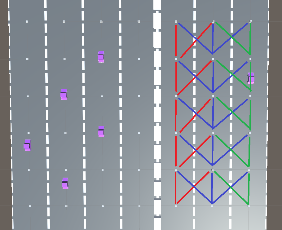
To create a simpler environment for the computer model, the environment has been defined with the use of nodes. These nodes are linked together, and these links describe possible paths for cars to drive on. A car can travel between nodes based on its own code. Every car will run the same code with minor (randomised) changes with regard to speed, braking time and takeover rates. An image of the node based system can be seen here: | |||
[[File:PRE2018_4_Group6_simulation_nodes.png]] | |||
The nodes are represented with white dots, and paths between them are represented with the colors red, green and blue. | |||
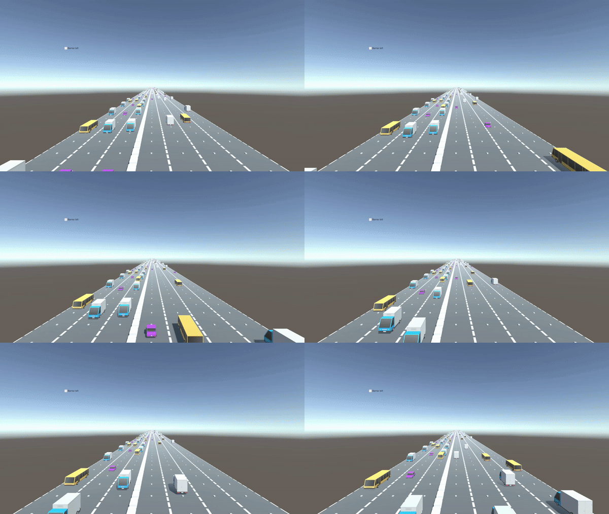
The simulation shown below is based on top of the mathematical research and data analytics which has been done using this project. | |||
The eventual simulation shows that the proposed solution is able to resolve congestions on one side of the road. | |||
[[File:PRE2018_4_Group6_simulation_anim.gif]] | |||
Some difficulties that have arisen from the simulation: | |||
* Drivers who do not have any experience with the proposed solution might be a little overwhelmed by the solution. | |||
* | * There are minor safety issues that have to be researched further. | ||
Successes that were proven by the simulation: | |||
* | * Is able to effectively adapt to overcome a congested roadside. | ||
* Most cars do not have any difficulty using the new technology. | |||
== References == | ==Conclusion== | ||
All in all, the design is beneficial to all major stakeholders. Additionally, no major ethical issues arise as a result of the design that prohibit the continuation of the project. Moreover, maintenance costs required to keep the device running are minimal at a constant cost of 24 euros per hour. Lastly, this project as a whole is not significantly more expensive than other potential solutions to the traffic problem. | |||
For our chosen road, it would have sufficed to simply only keep the device running during rush hours. This means that this solution would not be the most optimal for this specific road. However, we would suspect that this solution is extremely convenient for roads for which it is unrealizable to add more roads and which suddenly over-used. This over-usage could be caused by several factors such as for example new job opportunities for which the road in question needs to be crossed. Specific types of roads that come to mind are roads in the form of tunnels (especially through mountains) and bridges. | |||
==Discussion== | |||
*The concept is only tested on a specific segment. In following up research it should be advisable to the concept on other highways in the Netherlands. Form the project it does not become clear if the concept will work in the rest of the Netherlands. The following up research could include the simulation (or some improvements/add-ons on the simulation) from which a better result can be made. Secondly, it would be advisable to make real measurements about the traffic flow. With the use of a prototype, it would become possible to make measurements of the improvement of the traffic flow. With the use of the above-mentioned measurements, the results of this project can be improved. | |||
*It can be read in the conclusion that theoretical concept will work. From the results of the project, it does not become clear if the concept is able to be realised. It would be advisable to make a working prototype and measurements to obtain a conclusion if the concept is realisable. | |||
*The data represents only a small selection of the total time time. Only the most optimal settings were chosen by neglecting the weekends and holidays. The data which is chosen does gives a good representations of the real world. Especially when the standard deviation is taken into account. | |||
== References== | |||
1. Bielli, M., Ambrosino, G., & Boero, M. (1994). Artificial Intelligence Application in Traffic. Retrieved 4 mei 2019, van https://books.google.nl/books?hl=en&lr=&id=3cEEdaHrykAC&oi=fnd&pg=PA3&dq=artificial+intelligence+in+traffic&ots=0qYOXTFD1B&sig=akDTYf3nqHL0U26K8-rPSvZnP6k&redir_esc=y#v=onepage&q=artificial%20intelligence%20in%20traffic&f=false | 1. Bielli, M., Ambrosino, G., & Boero, M. (1994). Artificial Intelligence Application in Traffic. Retrieved 4 mei 2019, van https://books.google.nl/books?hl=en&lr=&id=3cEEdaHrykAC&oi=fnd&pg=PA3&dq=artificial+intelligence+in+traffic&ots=0qYOXTFD1B&sig=akDTYf3nqHL0U26K8-rPSvZnP6k&redir_esc=y#v=onepage&q=artificial%20intelligence%20in%20traffic&f=false | ||
| Line 282: | Line 378: | ||
11. Wang C., David B., Chalon R. (2014, 1-3 May). Dynamic road lane management: A smart city application. Retrieved 5 May 2019, from https://ieeexplore.ieee.org/document/6864085 | 11. Wang C., David B., Chalon R. (2014, 1-3 May). Dynamic road lane management: A smart city application. Retrieved 5 May 2019, from https://ieeexplore.ieee.org/document/6864085 | ||
This paper tries to create a good data vitalization related to in-city data collection and their appropriate diffusion to city actors (private and professional) and their services (applications). This is a important subject for a SMART CITY with important fields like ubiquitous computing (UC), ambient intelligence (AmI), connected vehicles (CV), and new styles of User Interfaces. They will go into further detail about a precise and specific context of a dynamic lane allocation system. | |||
12. Hausknecht M.m, Au T., Stone P., Fajardo D., Waller T. (2011, 5-7 Oct.). Dynamic lane reversal in traffic management. Retrieved 5 May 2019, from https://ieeexplore.ieee.org/document/6082932 | 12. Hausknecht M.m, Au T., Stone P., Fajardo D., Waller T. (2011, 5-7 Oct.). Dynamic lane reversal in traffic management. Retrieved 5 May 2019, from https://ieeexplore.ieee.org/document/6082932 | ||
This paper proposes a framework for dynamic lane reversal in which the lane directionality is updated quickly and automatically in response to instantaneous traffic conditions recorded by traffic sensors. They analyzed the conditions under which dynamic lane reversal is effective and propose an integer linear programming formulation and a bi-level programming formulation to compute the optimal lane reversal configuration that maximizes the traffic flow. In the experiments, active contraflow increases network efficiency by 72%. | |||
13. Amditis A., Bimpas M., Thomaidis G., Netto M. (2010, 8 July). A Situation-Adaptive Lane-Keeping Support System: Overview of the SAFELANE Approach. Retrieved 5 May 2019, form https://ieeexplore.ieee.org/document/5504223 | 13. Amditis A., Bimpas M., Thomaidis G., Netto M. (2010, 8 July). A Situation-Adaptive Lane-Keeping Support System: Overview of the SAFELANE Approach. Retrieved 5 May 2019, form https://ieeexplore.ieee.org/document/5504223 | ||
This paper gives an overview of a support system for an autonomous situation-adaptive road solution. The driver can be warned or corrected through suited actuators that are coupled to control strategies. The input to the system comes from cameras, which are supplemented by active sensors (such as radar and laser scanners) and vehicle dynamic data, digital road maps, and precise vehicle-positioning data. | |||
14. Chen Y., Krumm J. (n.d.). Probabilistic Modeling of Traffic Lanes from GPS Traces. Retrieved 5 May 2019 | 14. Chen Y., Krumm J. (n.d.). Probabilistic Modeling of Traffic Lanes from GPS Traces. Retrieved 5 May 2019 | ||
Useful information regarding this article is about computation of number and locations of driving lanes on a road. | |||
15. Yi R. (2016, 23 Jan). A Probability-Based Model of Traffic Flow. Retrieved 5 May 2019 | 15. Yi R. (2016, 23 Jan). A Probability-Based Model of Traffic Flow. Retrieved 5 May 2019 | ||
This article provides an introduction to the probabilities behind traffic flow theory both micro- and macroscopically. | |||
16. Calvert S.C., Taale H., Snelder M., Hoogendoorn S.P., (2012, June). Probability in traffic: a challenge for modelling. Retrieved 5 May 2019 | 16. Calvert S.C., Taale H., Snelder M., Hoogendoorn S.P., (2012, June). Probability in traffic: a challenge for modelling. Retrieved 5 May 2019 | ||
This article discusses the importance of a well defined and sufficiently developed model before one should start | |||
simulations regarding traffic flow. | |||
17. Caprani C., (2005, 10 Jan). Probalistic analysis of highway bridge traffic loading. Retrieved 5 May 2019 | 17. Caprani C., (2005, 10 Jan). Probalistic analysis of highway bridge traffic loading. Retrieved 5 May 2019 | ||
For our interest, this article goes in depth of development of new methods and statistical analysis. It also discusses | |||
potential solutions and reasons as to why they could not work. | |||
18. Li J., Gong S., Xiang T. (n.d.). Global Behaviour Inference using Probabilistic Latent Semantic Analysis. Retrieved 5 May 2019 | 18. Li J., Gong S., Xiang T. (n.d.). Global Behaviour Inference using Probabilistic Latent Semantic Analysis. Retrieved 5 May 2019 | ||
This article gives a very rigorous explanation to the mathematics that goes into constructing a model that intends to | |||
describe traffic flow mathematically. Both mathematical and computer analysis techniques have been discussed. | |||
19. Summala, Heikki. (2000). Brake Reaction Times and Driver Behavior Analysis. Transportation Human Factors. 2. 217-226. 10.1207/STHF0203_2. Retrieved 11 May 2019 from https://www.researchgate.net/publication/233039156_Brake_Reaction_Times_and_Driver_Behavior_Analysis | 19. Summala, Heikki. (2000). Brake Reaction Times and Driver Behavior Analysis. Transportation Human Factors. 2. 217-226. 10.1207/STHF0203_2. Retrieved 11 May 2019 from https://www.researchgate.net/publication/233039156_Brake_Reaction_Times_and_Driver_Behavior_Analysis | ||
In this article about driver brake reaction time (RTs) the writer rightly criticizes attempts to seek a canonical brake RT, and proposes to determine expected brake RT for specific situations. However, based on his analysis, he presents a series of values for expected, unexpected, and surprise situations that appear to generalize over a variety of different driver tasks and traffic situations without sufficient concern for urgency or criticality of the situations. | |||
20. Olson, P. L., & Sivak, M. (1986). Perception-Response Time to Unexpected Roadway Hazards. Human Factors, 28(1), 91–96. https://doi.org/10.1177/001872088602800110 | 20. Olson, P. L., & Sivak, M. (1986). Perception-Response Time to Unexpected Roadway Hazards. Human Factors, 28(1), 91–96. https://doi.org/10.1177/001872088602800110 | ||
This is another article about the driver analysis. It reflects on the perception-response (PR) time, the time from the first sighting of an obstacle until the driver applies the brakes, is an important component of stopping sight distance. In this study they measured the PR time of unalerted subjects to an obstacle in their lane encountered while cresting a hill. | |||
21. Kown, J., Varaiya, P. (2008). Effectiveness of California's High Occupancy Vehicle (HOV) system. Retrieved 10 May 2019 from https://www.researchgate.net/publication/222817805_Effectiveness_of_California's_High_Occupancy_Vehicle_HOV_system | 21. Kown, J., Varaiya, P. (2008). Effectiveness of California's High Occupancy Vehicle (HOV) system. Retrieved 10 May 2019 from https://www.researchgate.net/publication/222817805_Effectiveness_of_California's_High_Occupancy_Vehicle_HOV_system | ||
This article is about another technique of stopping traffic jams in the peak hours. The effectiveness of California’s 1171 mile High Occupancy Vehicle (HOV) system is assessed using peak hour traffic data from 700+ loop detector stations over many months. 7 conclusions in total were drawn on its performance. | |||
22. MIT, (n.d.). FLOW, SPEED, and DENSITY. Retrieved 20 May 2019 from | |||
https://lost-contact.mit.edu/afs/eos.ncsu.edu/info/ce400_info/www2/flow1.html | |||
This article gives a basis of concepts which aid in the understanding of a mathematical model of traffic flow. As the title suggests, the main concepts that are discussed are traffic flow, speed, and density. | |||
23. Cottrell, B.H. (1993), [https://rosap.ntl.bts.gov/view/dot/19352 Evaluation of a movable barrier concrete system]. | |||
This report reviews the cost, safety, and effectiveness of a movable barrier system used on highways. This system is not used for our specific use case (creating a flexible and reconfigurable road) but is used for road maintenance. The report analyses specific traffic accidents involving this system, as well as the advantages and disadvantages of the system overall. Eventually, the report states that the system performs adequately in the use case as described in the report. | |||
24. Satterfield, C. (2001)[https://www.fhwa.dot.gov/publications/publicroads/01julaug/workzone.cfm Moveable Barrier Solves Work-Zone Dilemma]. | |||
This article describes a movable barrier system used temporarily during the renovation of a bridge. In this instance three lanes are used, where the middle lane is used based on traffic needs. It also highlights the advantages and disadvantages of this and other types of systems. | |||
Latest revision as of 19:50, 24 June 2019
Group members
| Name | Student ID | Department |
|---|---|---|
| Tom Vredenbregt | 1221775 | Applied Physics |
| Jur Kappé | 1252895 | Applied Physics |
| Jannes van Poppelen | 1238120 | Applied Physics |
| Yannick de Jong | 1250663 | Applied Physics |
| Thom Smits | 1227659 | Applied Physics |
Organizational Matters
Task division & Planning
A planning has been made which we are supposed to stick to during the project. In this planning most of the things we have defined to be important/crucial for this project are mentioned. Aside from work on the wiki page, which everyone will do, the tasks are mostly divided amongst the group. The main focusses of the group are:
- Yannick: The simulation and making the solution smart.
- Thom: Analysis of the USE stakeholders, ethics.
- Tom: Mathemathics of the solution and creating of the model.
- Jur: Finding data, and analysing it, helping out Yannick.
- Jannes: Responsibility, Law, analysis use stakeholders.
Minutes
Throughout the course the group will have official meetings. A summary (minute) of what has been said/achieved in every meeting will be made. These summaries can be found here. This has been discontinued due to lazyness and for brevity.
Agendas
Like the minutes, the agendas made by the chair will be published. The agendas for the meetings can be found here.
Interview
We will try to interview do an interview with someone from Rijkswaterstaat, so that we can present our ideas and receive feedback for our idea. The interview questions can be found and the minutes of the interview can be seen in here.
Problem statement
The implementation of smart traffic lights in big cities reduces the travel time substantially. Whilst this makes the traffic flow more efficiently in the cities, a different solution has to be found to improve the traffic flow on highways. The ever increasing amount of traffic jams during the peak hours in the Netherlands(https://www.anwb.nl/verkeer/nieuws/nederland/2019/april/lichte-filegroei-in-eerste-kwartaal) is a call to arms to find solutions to this time-consuming phenomenon known as traffic congestion. One of these solutions is the routing of navigation systems that changes based on the activity on the highways. Traffic jams would be avoided by rerouting the navigation to go around the traffic jams, should it be the faster alternative. Of course, this solution is one of many, and it will contribute minimally on its own to the general problem. A different potential solution could be to simply add more lanes to each highway. Not only would this be very excessive outside of the peak hours, but it also would not be very cost- nor time efficient. For this reason, we propose to look for a solution in which we would optimize and change the current highways to a state in which it can, in fact, improve traffic flow in general. This solution we are proposing is the so-called "smart road". These lanes will adapt dynamically to the activity of both sides of the highway, as will be clarified visually later on. During morning peak hours, lanes highways towards big cities are usually very busy, whereas the lanes on the opposite side aren't that busy at all. Being able to distribute the lanes such that both sides would have a sufficient amount of lanes would benefit the traffic flow. The opposite directions would apply for evening peak hours. This solution would not only improve the traffic flow on highways during peak hours, but it would serve as a basis for the traffic flow outside of the peak hours. Coincidentally, this would also substantially reduce the emission that cars produce in traffic jams by continuously stopping and driving off. Central to this problem would be to research the question: Is the introduction of "smart roads" on the Dutch highways a viable solution to traffic congestion on Dutch highways?
Approach
Producing an actual prototype for a smart road in 8 weeks seems rather unlikely. Instead, the problem will be tackled by literature analysis, as well as a simulation of a smart road using a mathematically developed model. The final product for the project would, therefore, be a combination of a report about the literature analysis, together with the analyzed simulation of the smart road.
The literature analysis will include the USE aspects of the selected problem and an analysis of the present state of smart roads. In-depth analyses for user, society and enterprise stakeholders will be made. Since smart roads are designed to accommodate the users' needs, the focus will be on the user, its needs, and how to satisfy them.
The simulation of the smart road will be constructed using a mathematical model. Central in this mathematical model is a constructed norm which determines the orientation of the smart road. This norm is based on lane occupation on each side of the highway, as well as the time of the day to account for the peak hours. Whenever this norm is exceeded, the smart road will change in such a way that this norm is no longer exceeded. There is a couple of things that need to be accounted for in the simulation. One of which is the possibility of accidentally ending up on the wrong side of the highway as a result of the smart road adapting to its surroundings.
USE Stakeholders
The road which we chose to tackle is the A2 highway. The A2 is one of the busiest highways of the Netherlands and therefore would be a great road to try and optimize. It extends all the way from Maastricht to Amsterdam, with big cities like Eindhoven and Utrecht on its route. Analysing the entirety of this road would therefore be a big challenge, so instead a smaller part of the highway is chosen. Since this is a big highway, there are a couple of stakeholder involved. In this section these stakeholders will be analysed.
User
User stakeholders are by far the most important stakeholders out of all three of them. We had the idea to reduce traffic congestion on busy highways, which focuses on improving the experience of people driving on the chosen highway. Probably one of the biggest causes of congestion is due to the people travelling from their home to their work, and vice versa. On mornings and evenings of working days the highways are extremely packed. The morning peak hours are usually between 7:00 - 9:00 due to commuters going to work, whereas evening peak hours are usually between 17:00 - 19:00, due to the commuters travelling back home. The implementation of a smart just to account for the peak hours would be an extremely expensive solution, and there would be much cheaper alternatives. Instead smart roads should implemented to improve traffic flow even outside of the peak hours. This would give rise to new stakeholders to be analysed.
Pretty much all day long, traffic due to transport (trucks which move cargo) actively use the highways. These trucks are moving rather slow compared to regular traffic, since they usually drive around 80-90 km/h. Due to this slow speed they can cause congestion, especially when one truck decides to overtake another. The implementation of smart roads should also help improve conditions for this kind of traffic.
Like cargo transport, public transport is also a factor to be taken into consideration. This group consists mainly of buses, most of which drive according to a schedule. These schedules can be taken into consideration, but this is a tedious task. Due to the low presence of public transport on highways, they are not our main focus.
Yet another group of users are those who traverse the highways whenever they are going on vacation. This group can be divided in two subgroups. The first one is considered 'heavy' vacation traffic. This group contains all the people travelling with a caravan or motorhomes. Both of these are not allowed to drive faster than 80 km/h in the Netherlands, which is a substantial difference from the maximum allowed speed on Dutch highways. Buses are often also used in order to reach the vacation destination, and they also considered 'heavy' vacation traffic, but they coincide a bit with public transportation. The only difference between these is the frequency of their deployment. These vacation buses are most often used in vacation periods. The remaining group of traffic travels in regular vehicles. This group of users easily contributes to traffic congestion in vacation periods. Vacation periods are planned and thus a rough estimation of a lane distribution can be made in advance.
Emergency services are also considered to be a stakeholder for this problem. They hugely benefit from good traffic flow on the road, which makes their destinations more accessible. Traffic congestion is quite a problem for emergency services. Often no space can be made in between lanes such that the emergency vehicle can not pass. They however can use the emergency lane if it is accessible.
The last group of stakeholders to be considered are the drivers who use the highways for their own purpose. This group often avoids peak hours, and their presence is unlikely to cause congestion.
These users all come with their requirements, which have to be satisfied in order to create an efficient solution to traffic congestion. Commuters need well-maintained roads with sufficient capacity such that no traffic jams will occur during peak hours. The group who traverse highways during the vacation periods has a similar requirement. For them it is even more important that this is the case during the vacation periods. The other stakeholders have the same requirement. Traffic flows needs to be optimized, but this has to be the case throughout the entire day. All the stakeholders have the same requirements, but they have to be satisfied at different times of the day. For this reason a system that can dynamically change the lane distribution at different times of the day could be a good approach to minimize traffic congestion.
Society
There is only a couple of society stakeholders which play a role in the problem. The first of which are environmental organizations. These organizations are often involved in keeping the planet 'green'. They are not a supporter of keeping on adding extra lanes to the highways. Another concern they have is the emission of gasses by cars on the highways. Especially on congested roads this emission is high, since the vehicle have to drive off and stop the entire time. Their requirements can easily be fulfilled by the introduction of a system which can dynamically redistribute the lanes.
Another society stakeholder is the government. They are responsible for decisions made regarding the highways. They would like to keep the users of the road contempt. For them it is necessary that the roads are as optimized as possible.
Enterprise
Rijkswaterstaat is a governmental group which is responsible for the maintenance of the roads. Roads are constructed and maintained from the taxes that are paid by Dutch citizens. For them it is necessary that the implementation of a smart road is cost efficient. It should not have to cost more than it has to. Implementing an expensive smart road over a short distance is not very effective, and implementing one over a too long distance just gets very expensive. The right division has to be found. They also need the roads to be as simple as possible, for this would simplify the maintenance and construction of the roads (and its elements). The technology should not be too hard to maintain.
A different enterprise stakeholder are transport companies. These include both cargo transport, as well as public transport (e.g. buses & taxi's). The time spent on highways at which the traffic flows smoothly is minimized. In order to maximize their revenue, these enterprise therefore also require a smooth traffic flow on highways.
Constraints
The requirements from all of the stakeholders impose constraints on the design of the system which can turn the regular highway into an actual smart road. All of the user stakeholders, the environmental organizations and transport companies do not really impose any constraints on the design aside from the fact that road should not become less safe. The actual constraints arise from the government and Rijkswaterstaat.
The law
- The Wegenverkeerswet regulates the traffic and infrastructure of the Netherlands. This law states that the minimum acceptable speed for motorized vehicles that would like to use the highway is 60 km/h, whereas the maximum acceptable speed is 130 km/h. The design we have chosen dynamically moves the barriers over the road. It would look like a standing wave on the highway, instead it should just be look upon as a barrier moving machines that picks up and places concrete barriers, but now it is fully automized. The propagation speed of the barrier should not be higher than the maximum speed of the slowest moving vehicles on the highways. It should therefore never exceed 60 km/h.
The speed at which the barriers changes from lane to lane (perpendicular to the direction in which the highway is traversed) mustn't be too high. Drivers of vehicles could easily get scared with a barrier moving towards them with a high speed, which causes dangerous situations. This transition should happen smoothly.
- The second constraint arise from article 14 of the Wegenverkeerswet (https://wetten.overheid.nl/BWBR0001948/2017-09-01). This article states that each highway in the Netherlands should have a shoulder (berm). this could cause problem if extra lanes are added to solve the congestion problem, since in some cases there is not any space left for a shoulder. This constraint is pretty much always adhered to with the design we chose. The system divides the highway into two road going in opposite directions. No extra lanes would be added in this case, and therefore there will always be a shoulder at each side of the highway. This shoulder is, like all other roads, located right of most right lane for each direction of the highway.
Rijkswaterstaat
Aside from the constraints that result from the requirements of the USE stakeholders we came up with, an actual representative of one of the stakeholders can give feedback and perhaps impose more constraints which we work with. The interview questions can be found and the minutes of the interview can be found here. These constraints will get clearer after the interview with Rijkswaterstaat.
The location
The location that has been used for our concept is the road between Boxtel and Best on the A2 in the Netherlands. This road is in agreement with our constraints. This is because of the amount of car driving with the right distribution. Also the amount of lanes and distance of the route aare in agreement. The length of 13.8 km makes it perfect for the change of roads with the lanes. The highway can be seen in the route here.
Datasets of both in the lane towards Eindhoven (best) as towards 's-Hertogenbosch (boxtel) has been found on both locations. This makes four datasets in total which can be analysed.
Driver analysis
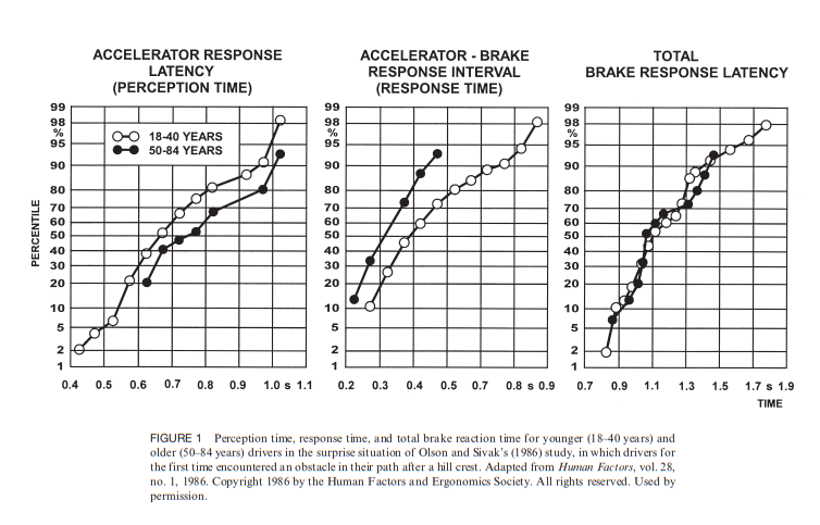
To simulate a road with traffic, a general idea of a basic human driver has to be implemented in code. In this simulation, it is assumed that everybody has an average response time with a slight (random) deviation each time. This response time is set to 1.4 seconds which is the 90th percentile according to this figure:
The random deviation that is taken is between -0.3 and 0.3 seconds, resulting in a final response time between 1.1 and 1.9 seconds
Tackling congestion
Several concepts could be implemented to improve traffic flow on highways. Some are dynamic, meaning that the lane division of the road will change with the amount of vehicles on each side of the road, whereas other are stationary, thus will not the change the lane division, and don't exhibit any kind of element a smart road would have. Several of these concepts will be analysed below. This analysis will provide a basis for the quality of each concept (to what extent the concept actually solves the problem). Moreover, it will also demonstrate that our selected option is the most viable one around. One thing to note considering the problem is that adding more and more lanes on either side of the road is not a solution. This would be quite an expensive and environmental irresponsible alternative, which is not desired.
Carpool lanes
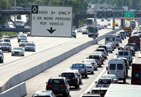
Carpool lanes (also sometimes called HOV-lanes) have already been around for a long time. They originate from the United States and Canada, but have also been present in Europe for quite a while (A1 Highway Netherlands, 1993). Their purpose is to minimize traffic congestion by allowing an extra lane for cars having multiple passengers. With the introduction of carpool lanes was also the intention to reduce the distance travelled by vehicles and thus minimize air pollution. It does not change the lane distribution, but instead adds an extra lane. It therefore would be a stationary solution to the main problem.
Figure ... Current day carpool lane on a busy interstate in the United States.
Since it has been around for quite some time we will not have to speculate about its effictiveness. The introduction of carpool lanes in the United States was said to reduce traffic congestion, but to what extent is this actually the case? Analysis of traffic data obtained in California disproves the claim [21]. Whilst this is just one example, it certainly is not the only one. First and probably most crucial is the fact that carpool lanes are heavily underutilized. Traffic flow and lane capacity during peak hours(the amount of vehicles passing a detector per hour per lane) is substantially lower than what is promoted. California Department of Transportation consider the traffic flow to be 1650 vehicles per hour per lane, but 80% of the samples are a marginable amount below this. So much less vehicles drive on carpool lanes compared to regular lanes. Furthermore, travel time that is saved by utilizing carpool lanes is rather small.
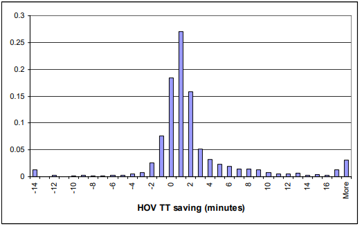
Figure ... Probabilty distribution of HOV travel time savings over a 10-mile route.
As can be seen from the figure above, the time save is minimal. The mean time saved is only 1.7, which is not so desirable as it will bare have an impact. A more desirable time save would be anywhere between five and ten minutes. However, the probability for the time save to be greater than 4 minutes is only 0.19, which is not that promising. On top of that, the small time save obtained by carpool does not encourage others to start carpooling. The analysis also concludes that the reduction of traffic congestion by the carpool lanes is almost negligible if regular lanes are allowed to be loaded with cars.
Carpool lanes therefore a rather poor solution to traffic congestion. They are merely usuable during the peak hours, as they lose their purpose outside of them, whenever it is not busy on the highways. Carpool lanes are a rather costly investment that would reduce congestion minimally and therefore would definetly not be the most optimal way to tackle the problem.
Stationary road barrier (slagboom-ish)
A different approach to reducing traffic congestion could be a stationary road barrier on each side of the road. Eventhough the barrier itself would be stationary, it will still have dynamic elements. Its implimentation is being experimented with in the United States already (apparently. bron + plaatje zoeken ). This system works well because of one lane that is in the middle of both sides of the road. This lane can be made available for either side whenever it is necessary to do so. Think for example about its use during peak hours. The extra available lane that is provided by this system for the direction in which it is necessary could improve traffic flow to such an extent that it will prevent any traffic jams.
(hier schets van systeem toevoegen)
This system (assuming one long extra lane) could theoretically also work in both directions of the road, just as carpool lanes do, but there is just one lane available. The edge this system has on carpool lanes is that it only requires the availability of one extra lane, instead of two lanes, which will reduce its cost substantially. Like carpool lanes, its most optimal use would be during peak hours, when it is quite busy on the roads. This system can also be used outside of the peak hours. It is not the most optimal, however. As only one side of the road can use the extra available lane at the time, the transition of the driving direction on the extra lane will not be the smoothest. To do this, first the lane has to be closed off for the side of the road it is made available for. Following that, the entiterity has to be cleared. Only after that has been done, the barrier for the other side can be opened. This process is quite time consuming, and thus is not the most optimal.
One way this could be solved would be to divide the lane into parts. This would allow for both directions to utilize the lane at the same time, at different locations. Eventhough the problem of transitioning is still there, the time it takes could be substantially reduced, which would allow for a more efficient traffic flow.
This system certainly can be a viable solution to the problem. It has the possibility to prevent traffic jams (or at least minimize the length of traffic jams), during and even outside of the peak hours. For the latter still a smooth way of transitioning has to be come up with but it certainly has potential. While it would be a better solution than carpool lanes, it still is not the most optimal one.
Movable barrier system
Movable barrier systems are a very promising dynamical solution to lane management on highways. These barriers are designed in such a way that they increase the capacity on the road by using the existing lanes and redistributing them, all whilst minimizing traffic congestion. This system is similar to the stationary barrier in the sense that both sides of the road can utilize the same lane, but at different times. Both sides of the road are seperated by a movable line of concrete barriers. These barriers can be moved in such a way that an extra lane will be made available to the side which needs it.
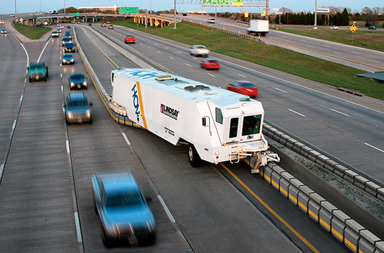
Figure... A barrier moving machine in action.
Currently, the only way to move these barriers is by using big machinery. The barriers are T-shaped concrete blocks, which are linked together. The machine then lifts the barriers up from the road, and passes them through its conveyor part.
The conveyor part can transfer up to 7.3 meter of barrier at once. When the part of the barrier is at the desired location, the barrier is gently placed on the road, such that it will not get damaged.
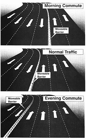
Instead of just having one lane to divide between both sides of the roads, this system can be used much more freely, as shown below.
Figure... Visualisation of the freedom of the barrier movement system. Credit: Rob Bain (http://www.robbain.com/Moveable%20Barrier.pdf)
In the picture, three different lane distributions can be seen, depending on the time of the day. The barrier can be moved in such a way that it accomodates both directions of the road. Starting the redistribution timely can completely prevent any traffic congestion during peak hours. For this to work, the road needs to have a lot of lanes. An example of such a road would be the A2 between Utrecht and Amsterdam. The system could also be applied outside of peak hours to improve the traffic flow. Since the behaviour on the road is hard to predict, the speed of the machine matters a lot.
If instead of big machines, this barrier system could be automated, it could also be applied over much longer distances, and it would happen much faster. Automation of the barrier system will cut the time it takes to redistribute the lane tremendously. Since the movable barrier system has not been introduced for a long time, automation will be a long term goal in the future and thus might take a while.
The movable barrier system has a lot of potential. When the system is used on time for the bigger highways it can seriously improve traffic flow. The only drawback it has from being actively used is the amount of time it takes to move the barriers. As of now, this process is rather slow, but once it speeds up, this system can be a good solution to traffic congestion.
Flexible lines
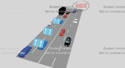
A somewhat similar solution to the movable barriers is using flexible lines. These are lines that can be changed from straight to broken lines, and vice versa, to indicate the lane distribution of the road. A straight line would indicate where the travelling directions are seperated, and broken lines would be used to indicate where the lanes are seperated from eachother, just like what is currently the case, too. A visualisation can be seen below.
Figure ... Visualisation of a road with flexible lines. The effect of the flexible lines can not yet be seen.
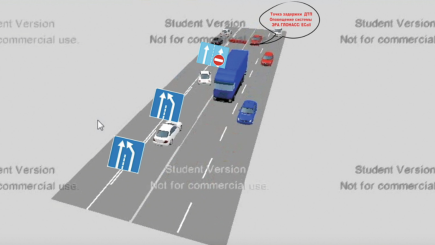
A system like this will be superiour to the movable barrier system in a lot of ways. The time it takes to move the lines is substantially lower than the time it takes to move the barriers. This would already solve one of the problems that the movable barrier had. The short time it will take to the redistribute the lane makes the flexible lines very flexible. One instance this could be used is to timely indicated any obstacles on the road for example.
Figure ... Visualisation of a road which had its lines changed in order to redistribute the lanes.
Since the presence of the obstacle can be detected on time, the lines can be changed in such a way that the car can avoid it on time, thus preventing any possible congestion.
Just like all other mentioned systems, the flexible line system can be used to redistribute the lane division during the peak hours, to prevent any congestion and to improve the traffic flow. Even outside of the peak hours this system can be used to improve traffic flow at areas where it needs improvement.
The introduction of a system as such does come with its disadvantages. The barrier system had a barrier two seperate both the directions of travelling traffic. Since this system can redistribute the road into any configuration, the travelling directions can not be seperated but by a line. This ofcourse is rather dangerous on a road where vehicles move with high speeds. A different issue is to determine what the lines will be made of. It needs to be something which does not take a long time to change. Concrete barriers will not work. One possibility could be using lights. This again would impose some difficulties. Using lights would only work whenever it is dark outside. A different alternative would have to be found during the day, which still passes all constraints.
Flexible lines are a promising solution. It is definetly one of the better solutions against traffic congestion, but it comes with its difficulties. If a solution to these difficulties has been found it will surely be the better solution out of all the ones previously mentioned.
Data Analysis
The data of the intensity and Average speed is received from the Site of 'Nationale Databank Wegverkeersgegevens'. The data about the vehicle category is received from the site of TNO. The data has been analysed and processed in the following file: File:Speed Intensity Category.zip.
The data from four different places has been requested. Namely two in Best, one towards Den Bosch (51.5190323;5.3982506) and towards Eindhoven(51.5189078;5.3981406), and two in Boxtel, one towards Den Bosch (51.6182637;5.3169165) and towards Eindhoven (51.6180882;5.3167447).
In these four places, all velocities and intensities has been searched up and selected per month. 12 Months in total beginning from 22-5-2018 till 21-5-2019. These data sets represent each Monday till Friday excluding the holidays. Therefor these data sets represents the same kind of information and is more reliable for our modelling.
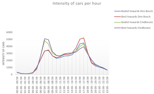
From these 12 months both the average is calculated as the standard deviation per hour. These are then plotted per measurement place over the hours. This has been done for the Intensity and the average speed. For the length of the cars passing the highway another method has been used. The results can be seen down below.
Intensity
The intensity is plotted per hour for all four measurements points. Also the standard deviation is calculated.
Average speed
The average speed is also plotted per hour with the standard deviation.
Vehicle category
The kind of vehicles passing by is determined apart from the intensities, but both data sets give a representation of the highways in The Netherlands.
An additional vital piece of data that has been required is the theoretical value of the critical density. This concept is further explained in the section about the mathematical model and holds a value of approximately 131 vehicles per lane mile (MIT).
Survey Analysis
In order to get a little bit more familiar with the users we sent out a survey. This survey allows us to determine the relevance of our selected problem. We knew beforehand what kind of answers we were going to receive, as we are also part of the user stakeholders. The questions of the survey are rather trivial and they are answered by 24 recipients. One thing to note beforehand is that 24 recipients is not very representative of all the inhabitants of the Netherlands. The survey, and answers to the questions, in Dutch, are provided below.
Even though the amount of recipients of the survey is quite low, there is still some important information that can be extracted from the survey. As we expected, almost everyone gets frustrated from traffic congestion caused by slower moving vehicles. All of the recipients try to minimize congestion be driving at at least the maximum speed. Occasionally there are is a couple that follows the behaviour of other drivers on the road. This also has the effect to reduce congestion, provided that this speed is not substantially lower than the maximum speed. To our surprise, over half of the recipients has answered that they rarely deal with traffic jams due to congestion. A third has answered that traffic congestion often is a problem for them. We think that this remarkable result is a result of the small group of recipients of the survey. Lastly, almost all of the recipients agreed that small grooves in the road would be pretty annoying. This latter results has been used when designing the smart road, as we needed to keep the user satisfied.
The concept
During the meeting on 17-05, we eliminated some potential solutions for the congestion problem. Neither carpool lanes, nor the stationary road barrier seemed like the most optimal solution for this problem. Instead, the latter two out of four have been chosen, the best of both solutions are combined to create what we believe will be the most optimal way to decrease traffic congestion.
The design combines the concepts of the flexible lines and the movable barrier system. One flaw that was present in the flexible lines concept was how to actually draw the lines between the lanes. We figured that implementing the concrete barriers, the same ones as from the movable barrier system could work out quite well. This would also mean that the big machine that moves the barriers would be obsolete. We wanted the barriers to move independently. The barriers, again with dimensions like such[1], would be placed on some sort of rails in between the lanes. A visualization of the concept can be found below.
Some parts of the barrier (pivots), would be able to move horizontally over the road, which would cause the other barriers, attached to these pivot barriers, to follow them. The barriers would sort of move like a snake in between the roads. After the pivot barriers move horizontally and have reached their destination, the barriers lock in place.
A concept like this is very dynamical, in the sense that it can be applied according to the situations on the road. Its application is not just limited to peak hours, but it can even be used to reduce congestion outside of them when applied timely. It takes the best of both of our concepts and combines them to create the most optimal solution. It is very flexible, and it can be used much faster, and thus also more efficient than the big machine that would independently move the barriers, at a rather slow pace. This concept also comes with its constraints:
- The number of lanes for which this concept can be applied is at least 3. In this case, it would only have one extra lane to divide between both sides of the road. The distribution of the lanes will be more optimal if there are more roads available which the system can be used.
- The system needs to be powered. The concrete barriers cannot move by themselves. Since we no longer want them to be moved by a big machine, they need to be powered, and some movement mechanism has to be come up with.
- The speed at which the barriers move must be below maximal value. When the speed at which the barriers move is too fast, other vehicles can be cut off, which could cause dangerous situations.
- The barrier needs to be able to withstand the impulse of a vehicle that impacts on it. This means that it should remain standing, stationary and undamaged after potential collisions.
Design of the barrier blocks
The moveable barrier will be divided into segments of concrete blocks (these blocks will have a width of 0.5m, the height of 0.99m and length 0.5m and will have a weight of 680 kg). In order to let the barrier moveable all the segments will be placed on four wheels (each in one corner). Every wheel will be mounted with brakes. These brakes need to be strong enough such that the barrier won’t move if a vehicle collided with the barrier. These brakes will prevent the barrier from moving when they shouldn’t move (in the case of a collision or a malfunction of the system). In order to keep the segments moving to the correct position, the motorised segments will have a camera. With the use of the camera the road will be scanned for recognised points (which are in this case the white stripes of the lanes). With the use of the cameras and the white strips, the segments are calibrated such that will be placed at the correct position on the road. In the figure below a bottom view of a random segment is showed.
In order to let the barrier move like a snake or sling some of the segments will be mounted with a motor. Not every segment will be motorised (this is in order to keep the cost down). All the segments will be grouped into groups of 15, not motorised concrete blocks and 2 motorised blocks. The motorised segments will be placed at the front and the end of the group. The segments will be connected with each other in two ways. Firstly, every segment will have at on side a spherical fork and at the other and a bowl in which the spherical fork is placed. This coupling system makes that the barrier can move as a uniform sling. The coupling system can be seen in the figure below.
The second connecting is made with a mobile cable in which the electrical wire is placed. The cable should be water prove, such that the electrical wire cannot be damaged. The cable should be flexible such that it can move along with the segments. The electrical wire is for powering the electrical motor in the motorised segments and for the cameras at the bottom. The cameras are only placed at the motorised segments (again to keep the cost low and they’re not needed at the no motorised parts). In order to keep the weight of the segments low, the inside of the segments is filled with foam. The electrical parts are placed parallel, such that when one motor fails the other segments keep working.
Ethics
Ethical consideration
In order to take the considerations of the users into account, ethical consideration is made. This is done such that by designing the smart road, the users' constraints and requirements are not forgotten. For the other stakeholders, it is possible to get contact and obtain their requirements and constraints. With the use of the coming ethical consideration (on the basis of the utilism and Kantism) it possible to view what is possible and what isn't possible in other to keep the users in mind.
Utilitarianism
A short recap of utilism: in utilism, it is the goal to perform an action such that it leads to the happiness of most people. A short sidenote: the quality of happiness is also important in the consideration which action to do. In general, a utilitarian would want a road which is designed in such a way that most people who use the road the most often would like and be happy with this road. It is important to look at the most often users of the road, this is because this group of users are having to deal the most with the designed solution (think by these users of transport traffic, commuters etc.). For these stakeholders, it is important that the road user-friendly such that is pleasant to ride the road (no speedbumps or low-quality roads (like the Belgian roads). Secondly, it is important that it is clear how to uses the road (with respect to the designed smart road). If the road is unclear how to use, it would lead to people who get irritated or unhappy with the designed road. A utilitarian would disapprove this because it (in this case) does not lead to the most happiness for the most people. So when designing the smart road and the users are approached by a utilitarian way of thinking, it is important to keep in mind that the most important stakeholders are the users who use the road the most often and that the solution would lead to the most happiness of most people (an important: the most happiness in the group of the most often users).
Deontology
The first rule of deontology is that when something is bad it will always be bad even when the results/outcoming is good. To apply this rule it is important to determine what is bad. this can be a tricky job. But this ethical consideration is made such that the users will get a voice and the project/design is linked to the needs/requirements/constraints of the users. With this said, the determination of what is bad becomes a lot easier. Here what is bad is determined as what is bad or unpleased for the users. So as an example, when the road is altered in such a way that it brings down the comfortableness of the road for the users it can be seen as bad. So bumps, rails, bad quality, etc. which will bring down the comfortableness of the road can be seen, form a deontology point of view, can be seen as bad. So it does not matter if the results (better traffic flow or a better road) is good, the way to achieve this is bad so the result will also be bad. In the theorem of deontology, Kantianism is an important theorem. This consisted of three laws (or Categorical Imperative) which are (from https://en.wikipedia.org/wiki/Kantianism):
- Act only according to that maxim whereby you can at the same time will that it should become an universal law
- Act in such a way that you treat humanity, whether in your own person or in the person of any other, never merely as a means to an end, but always at the same time as an end.
- Therefore, every rational being must so act as if he were through his maxim always a legislating member in the universal kingdom of ends.
When these 3 rules are applied to the designed solution, the requirements/constraints of the users are taken into account of the problem. Form the first Categorical Imperative it becomes clear that some law can be set up in advance. The first Categorical Imperative mostly gives more general constraints. It is important to take these general constraints into account by the design of the solution. Which these general constraints it is most likely to obtain a solution which leads to the satisfaction of the most users (which is also what an utilitarian wants to obtain). Some of these rules/constraints are:
- Everbody wants a comfortable/good road so form this it follows that: it can be an universal law that all roads should be comfortable and form a good quality.
- Every designed solution should be designed in such a way that solution is safe for the stakeholders.
- Form the second named rule/constrain it follows that the designed solution should be easy to use.
Form the second Categorical Imperative also some constraints on the solution occur. Form an engineering point of view the easiest and most efficient solution is seen as the best solution. But in some cases, this will lead to interference with the second Categorical Imperative. The dynamical road (smart road) can be designed the most efficient when the barrier is placed on rails and is moved in such a way. But this is in conflict with the second Categorical Imperative, the comfortableness of the road has much to suffer from this solution. Here humans are not taken as a goal, but a tool to obtain the best possible traffic flow which is a conflict with the second Categorical Imperative. Also, in other solutions in which the users are not set as the goal but as a tool to obtain the best possible traffic flow.
Conclusion
In conclusion of the ethical consideration, it can be concluded that virtue ethics is not useful to take into account by design the smart road. Virtue ethics does not necessarily lead to constraints of requirements form the stakeholders. It will display the virtue of road users like the speeding limit (from https://www.universiteitleiden.nl/binaries/content/assets/customsites/study-abroad-exchange-students/road_traffic_signs_and_regulations_jan_2013_uk.pdf) or how should I use the road. Form this, it won't become clear what the constraints would be, but form virtue ethics it is possible to determine some requirements road users needed. The needs/requirements and constraints of the users can be best explained with the use of the ethical consideration, where the Virtue (only the requirements), Utilitarian and Kant's ethics are combined. Here the Utilitarian is the most important view to use because it is the easiest to use, but also it gives the most disguised requirements and constraints for the user stakeholders. With the use of this ethical consideration, the link between the designed smart road and the road users is made. With this section, the user's stakeholders are explained and given a voice such that these stakeholders aren't ignored and are considered. With this, the designed road will be the best possible solution for all the stakeholders. When the utilitarian and deontological point of view is combined, a complete view of the requirements/constraints forms the user's point of view is given. When using deontology, the second Categorical Imperative is maybe an important rule to keep in mind. Form the first Categorical Imperative some standard constraints (which are still important) or more general rules occur. The second Categorical Imperative actual makes it really sure that users aren't ignored. At last a cost-benefit comparison is made which is given:
Responsibility
In case any accidents happens it is of crucial to know what party is responsible. Like is the cast in most cases, it all depends on the circumstances under which the accident happens. Rijkswaterstaat is responsible for its roads. Implementation of the smart roads means that the responsibility lies with them, in most cases. If the software controlling the barrier malfunctions or if any part of the barrier is malfunctioning, then Rijkswaterstaat is fully responsible. These two cases are only possible if the maintenance, which is done by Rijkswaterstaat, is very poor. Should either of these two be the case then the option to disable the entire barrier should be available. In practice this means that someone would put the barriers on handbrake. They should no longer be able to move, so that even more dangerous situations can be prevented. This would also work if the barrier is in the middle of transitioning between lanes. Due to the design of the barrier, cars can still go around it like how they normally would, but now the barrier is just stationary. This could cause a bit of trouble if the barrier remains stationary for a long time. Suppose the lanes of the road are distributed in a way that is inefficient during the peak hours. Since the emergency button is pushed, someone from Rijkswaterstaat has to fix the barrier. This could be a time consuming process, and if this does not happen fast enough then traffic congestion is inevitable. As mentioned before, the responsibility does not always lie with Rijkswaterstaat. In case of any unpredictable accident, such as a vehicle deliberately driving into the barrier. Rijkswaterstaat can not account for actions like such and therefore should not be responsible.
Mathematical model
For the mathematical model, the real-life issue is required to be translated into the mathematical language. We would prefer to have the model to be as simple as possible. This could be accomplished by viewing the propagation direction the cars on the road to be represented by a piece of the real number line. Define the whole set of real numbers to be the road space. Then, create a twofold partition of the road space where we have one of the subspaces nonempty, closed, and bounded: called [math]\displaystyle{ \Delta x }[/math]. We let L denote the actual trace of the propagation direction in three-dimensional Euclidean space. The potential issue here is that L could trace a nonlinear path which might not be able to be mapped to our [math]\displaystyle{ \Delta x }[/math]. For [math]\displaystyle{ \Delta x }[/math] to be able to represent our road L we need the existence of the following mapping: . This is a bijective map which maps every point on L to a unique point on our partition and vice versa. If we also take L to be nonempty, closed and bounded, we can apply the theorem of Heine-Borel to show that these two curves are homeomorphic. This implies that the mapping exists and that the subspace of the road space is an accurate representation of our propagation trace of the road. Lastly, the property
needs to be imposed on the function. Basically, this property ensures that for all points P that are in further along in the parametrization of L than point A (element in L), have a greater real value than the preimage of point A.
Now that a model for the road has been constructed, math can be performed on said model. The main issue at hand is the formation of a traffic jam, which can be described by the car density approaching a certain 'critical level'. In the case of one lane, the car density can be denoted by [math]\displaystyle{ \rho }[/math]=n/[math]\displaystyle{ \Delta }[/math]x, where [math]\displaystyle{ n }[/math] is the number of cars present in the partition of the road [math]\displaystyle{ \Delta x }[/math].
Next, it is important to realize that the cars do not only take up their length l, but also the distance to the next car that follows. For the model, it is assumed that cars maintain a minimum distance from the car in front of them to prevent crashes. In total, the space an event takes up can be defined by s=d+l. Here, d is the distance between the front of a car and the back of the car proceeding it, s is the total defined space a car takes up. It can now be seen that the partition can also be written as , where s-subscript-i denotes the spacing of the i-th car and N the total number of cars present in the partition. When this expression is substituted into the density equation we get that
, where s-bar denotes the average spacing between cars. These equations allow for a relation between density and cars without having an explicit partition length dependence.
This model can easily be extended to multiple lanes: 

And hence:
Lastly, here as demonstrated for single lane models, an equation for the critical density can be formulated: 
Now that a general description of the environment has been formulated in terms of mathematics, it can be applied to the computer simulation. From the data on our specific road as described earlier, we have numbers regarding the average amount of cars per hour with their corresponding speeds. These numbers are given for all 24 hours of the day for a variety of vehicle sizes and are taken over a years' time. The arrival of the cars in our partition, it can be viewed as a birth-death process for which we have the Poisson random variable. One should note one of the properties of Poisson distributions: then the inter-arrival times in the interval [0,t] are independently and identically distributed as
. Using this probability distribution, a random number can be assigned to the difference in arrival times between cars in the computer simulation. Additionally, the cars are given a certain speed based on the data and maintain a finite variance over a sample size that is sufficiently large. Hence, according to the Central Limit Theorem, the vehicle speed distribution can be modeled by means of a Gaussian distribution:
. With this information, the simulation keeps track of the spacing between cars and as a result also the average spacing per lane. Should the average spacing get close to the reciprocal of the critical density as described by the equations above, then the program will allow for a change of lanes by means of the moving barrier. The program will perform such based on past data and predictions to prevent the critical state from being reached and hence preventing traffic jams to occur.
Simulation
The simulation will be made using the Unity3D software package. This software package will allow for relatively easy 3D simulations using ready-made models. It also includes physics simulations and scriptable interfaces.[2] The simulation will simulate our proposed solution to the A2 traffic problem. It will, therefore, consist of 7 lanes, with a middle lane which can change direction. To create a simpler environment for the computer model, the environment has been defined with the use of nodes. These nodes are linked together, and these links describe possible paths for cars to drive on. A car can travel between nodes based on its own code. Every car will run the same code with minor (randomised) changes with regard to speed, braking time and takeover rates. An image of the node based system can be seen here:
The nodes are represented with white dots, and paths between them are represented with the colors red, green and blue.
The simulation shown below is based on top of the mathematical research and data analytics which has been done using this project.
The eventual simulation shows that the proposed solution is able to resolve congestions on one side of the road.
Some difficulties that have arisen from the simulation:
- Drivers who do not have any experience with the proposed solution might be a little overwhelmed by the solution.
- There are minor safety issues that have to be researched further.
Successes that were proven by the simulation:
- Is able to effectively adapt to overcome a congested roadside.
- Most cars do not have any difficulty using the new technology.
Conclusion
All in all, the design is beneficial to all major stakeholders. Additionally, no major ethical issues arise as a result of the design that prohibit the continuation of the project. Moreover, maintenance costs required to keep the device running are minimal at a constant cost of 24 euros per hour. Lastly, this project as a whole is not significantly more expensive than other potential solutions to the traffic problem. For our chosen road, it would have sufficed to simply only keep the device running during rush hours. This means that this solution would not be the most optimal for this specific road. However, we would suspect that this solution is extremely convenient for roads for which it is unrealizable to add more roads and which suddenly over-used. This over-usage could be caused by several factors such as for example new job opportunities for which the road in question needs to be crossed. Specific types of roads that come to mind are roads in the form of tunnels (especially through mountains) and bridges.
Discussion
- The concept is only tested on a specific segment. In following up research it should be advisable to the concept on other highways in the Netherlands. Form the project it does not become clear if the concept will work in the rest of the Netherlands. The following up research could include the simulation (or some improvements/add-ons on the simulation) from which a better result can be made. Secondly, it would be advisable to make real measurements about the traffic flow. With the use of a prototype, it would become possible to make measurements of the improvement of the traffic flow. With the use of the above-mentioned measurements, the results of this project can be improved.
- It can be read in the conclusion that theoretical concept will work. From the results of the project, it does not become clear if the concept is able to be realised. It would be advisable to make a working prototype and measurements to obtain a conclusion if the concept is realisable.
- The data represents only a small selection of the total time time. Only the most optimal settings were chosen by neglecting the weekends and holidays. The data which is chosen does gives a good representations of the real world. Especially when the standard deviation is taken into account.
References
1. Bielli, M., Ambrosino, G., & Boero, M. (1994). Artificial Intelligence Application in Traffic. Retrieved 4 mei 2019, van https://books.google.nl/books?hl=en&lr=&id=3cEEdaHrykAC&oi=fnd&pg=PA3&dq=artificial+intelligence+in+traffic&ots=0qYOXTFD1B&sig=akDTYf3nqHL0U26K8-rPSvZnP6k&redir_esc=y#v=onepage&q=artificial%20intelligence%20in%20traffic&f=false
This Article provides information about the development and the applications of AI in traffic and transport. All difficulties of discerning the role and worth of the AI techniques are discussed. The algorithm provides solutions in the area's from traffic control, logistics and highway management.
2. Li, L., Lv, Y., & Wang, F. (2016a, 10 Juli). Traffic signal timing via deep reinforcement learning - IEEE Journals & Magazine. Retrieved 4 mei 2019, from https://ieeexplore.ieee.org/abstract/document/7508798
In this paper the author writes about a set of algorithms to designs signal timing plans via deep reinforcement learning. This approach is usefull in order to set up a deep neural network which can learn from the sampled traffic state/control input and the corresponding traffic system performance output. Using this most idealized network the best signal timing policies can be decided. in this paper provides possible benefits of this approach and will discuss the relation between the already existing approaches.
3. Contreras, S., Kachroo, P., & Agarwal, S. (2016, 1 maart). Observability and Sensor Placement Problem on Highway Segments: A Traffic Dynamics-Based Approach - IEEE Journals & Magazine. Retrieved 4 mei 2019, from https://ieeexplore.ieee.org/abstract/document/7317783
This source is about ways to collect data of the road as efficient as possible using sensors. This data may then be used to reduce traffic congestion. The sensors has to maximize the information collected and minimize monetary cost. This journal will talk about the observability problem in terms of sensor placement and then present a method for comparing different scenario's for different sensor placement.
4. Satyanarayana, M. (1970, 1 January). Intelligent Traffic System to Reduce Waiting Time at Traffic Signals f. Retrieved 4 mei 2019, from https://link.springer.com/chapter/10.1007/978-981-10-7868-2_28
The research of this conference paper is about how to control the traffic issues in developing countries as India. The enormous amount of cars adding each day plus the path of emergency service vehicles are a hugh problem in the countries. This papar will provide better solutions for these two problems based in the latest technology called the Internet of Things.
5. NDW (z.d.). Documenten - Nationale Databank Wegverkeersgegevens. Retrieved 4 mei 2019, from https://www.ndw.nu/documenten/nl/
A Database from the "National Databank Wegverkeersgegevens" with information about the dutch roadways. With for example the measuring locations, travel times, speeds and intensities of the cars.
6. NDW, C. B. S. (2018, 1 maart). CBS Statline. Retrieved 4 mei 2019, from https://opendata.cbs.nl/#/CBS/nl/navigatieScherm/zoeken?searchKeywords=*&page=1&theme%5B%5D=422
This cite provides several databases related to the traffic flows and important data about the users driving behavior. It also has an important database for which kind of traffic is on the road.
7. Walraven, E. (2016, 1 June). Traffic flow optimization: A reinforcement learning approach. Retrieved 4 mei 2019, from https://www.sciencedirect.com/science/article/abs/pii/S0952197616000038
Traffic congestion causes important problems such as delays, increased fuel consumption and pollution. This paper will provide a way to formulate any traffic problem as a Markov Decision Process. From that a Q-learning algorithm will learn a policy dictating the maximum driving speed such that traffic congestion is reduced. This solution will not only take into account the existing approaches, but it will also take traffic predictions into account. And as a final point the author will show you using a simulation experiment that the predicted optimal speed limits will help reducing the traffic congestion.
8. Nguyen T. (2018, 16-19 Sept.). Ahead of the Curb: Smart Roads. Retrieved 5 May 2019, from https://ieeexplore.ieee.org/document/8656667
This article tries to improve the road quality using Big Data, new technology and on-demand information. Two ideas 'Smart Road technology' and 'Dynamic Road Markings' will be explored in order to revolutionize these roads by creating an on-demand system adjesting lanes to any vehicle, bike or pedestrian traffic. The quality will be improved on points as mobility, sustainability, safety and accessibility.
9. El-Wakeel A., Li J., Rahman M. (2017, 14-16 Nov). Monitoring road surface anomalies towards dynamic road mapping for future smart cities. Retrieved 5 May 2019, from https://ieeexplore.ieee.org/document/8309076
The development of Smart Cities aims to transform city infrastructures and services through the use of information and communication technologies. One aspect of Smart City applications is the demand for more efficient and safe transportation systems. Specifically, road anomalies are some of the challenges that contribute to the increase in vehicle damage and decrease in driver safety. This paper proposes a road surface condition monitoring system that utilizes low cost MEMS acceleration sensors and GPS receivers within a tablet to detect and localize road surface anomalies.
10. Arbi Z., Belkahla O., Sbai M.K. (2017, 17-19 Feb). A multi-agent system for monitoring and regulating road traffic in a smart city. Retrieved 5 May 2019, from https://ieeexplore.ieee.org/document/8071843
This paper designs a multi-agent system to monitor road traffic in a smart city and dynamically adjust, in a distributed manner, traffic lights duration to traffic densities at different road sections. This will done in order to minimize both locally and globally waiting times by the anticipating abilities of modern agents and their communication abilities.
11. Wang C., David B., Chalon R. (2014, 1-3 May). Dynamic road lane management: A smart city application. Retrieved 5 May 2019, from https://ieeexplore.ieee.org/document/6864085
This paper tries to create a good data vitalization related to in-city data collection and their appropriate diffusion to city actors (private and professional) and their services (applications). This is a important subject for a SMART CITY with important fields like ubiquitous computing (UC), ambient intelligence (AmI), connected vehicles (CV), and new styles of User Interfaces. They will go into further detail about a precise and specific context of a dynamic lane allocation system.
12. Hausknecht M.m, Au T., Stone P., Fajardo D., Waller T. (2011, 5-7 Oct.). Dynamic lane reversal in traffic management. Retrieved 5 May 2019, from https://ieeexplore.ieee.org/document/6082932
This paper proposes a framework for dynamic lane reversal in which the lane directionality is updated quickly and automatically in response to instantaneous traffic conditions recorded by traffic sensors. They analyzed the conditions under which dynamic lane reversal is effective and propose an integer linear programming formulation and a bi-level programming formulation to compute the optimal lane reversal configuration that maximizes the traffic flow. In the experiments, active contraflow increases network efficiency by 72%.
13. Amditis A., Bimpas M., Thomaidis G., Netto M. (2010, 8 July). A Situation-Adaptive Lane-Keeping Support System: Overview of the SAFELANE Approach. Retrieved 5 May 2019, form https://ieeexplore.ieee.org/document/5504223
This paper gives an overview of a support system for an autonomous situation-adaptive road solution. The driver can be warned or corrected through suited actuators that are coupled to control strategies. The input to the system comes from cameras, which are supplemented by active sensors (such as radar and laser scanners) and vehicle dynamic data, digital road maps, and precise vehicle-positioning data.
14. Chen Y., Krumm J. (n.d.). Probabilistic Modeling of Traffic Lanes from GPS Traces. Retrieved 5 May 2019
Useful information regarding this article is about computation of number and locations of driving lanes on a road.
15. Yi R. (2016, 23 Jan). A Probability-Based Model of Traffic Flow. Retrieved 5 May 2019
This article provides an introduction to the probabilities behind traffic flow theory both micro- and macroscopically.
16. Calvert S.C., Taale H., Snelder M., Hoogendoorn S.P., (2012, June). Probability in traffic: a challenge for modelling. Retrieved 5 May 2019
This article discusses the importance of a well defined and sufficiently developed model before one should start
simulations regarding traffic flow.
17. Caprani C., (2005, 10 Jan). Probalistic analysis of highway bridge traffic loading. Retrieved 5 May 2019
For our interest, this article goes in depth of development of new methods and statistical analysis. It also discusses
potential solutions and reasons as to why they could not work.
18. Li J., Gong S., Xiang T. (n.d.). Global Behaviour Inference using Probabilistic Latent Semantic Analysis. Retrieved 5 May 2019
This article gives a very rigorous explanation to the mathematics that goes into constructing a model that intends to describe traffic flow mathematically. Both mathematical and computer analysis techniques have been discussed.
19. Summala, Heikki. (2000). Brake Reaction Times and Driver Behavior Analysis. Transportation Human Factors. 2. 217-226. 10.1207/STHF0203_2. Retrieved 11 May 2019 from https://www.researchgate.net/publication/233039156_Brake_Reaction_Times_and_Driver_Behavior_Analysis
In this article about driver brake reaction time (RTs) the writer rightly criticizes attempts to seek a canonical brake RT, and proposes to determine expected brake RT for specific situations. However, based on his analysis, he presents a series of values for expected, unexpected, and surprise situations that appear to generalize over a variety of different driver tasks and traffic situations without sufficient concern for urgency or criticality of the situations.
20. Olson, P. L., & Sivak, M. (1986). Perception-Response Time to Unexpected Roadway Hazards. Human Factors, 28(1), 91–96. https://doi.org/10.1177/001872088602800110
This is another article about the driver analysis. It reflects on the perception-response (PR) time, the time from the first sighting of an obstacle until the driver applies the brakes, is an important component of stopping sight distance. In this study they measured the PR time of unalerted subjects to an obstacle in their lane encountered while cresting a hill.
21. Kown, J., Varaiya, P. (2008). Effectiveness of California's High Occupancy Vehicle (HOV) system. Retrieved 10 May 2019 from https://www.researchgate.net/publication/222817805_Effectiveness_of_California's_High_Occupancy_Vehicle_HOV_system
This article is about another technique of stopping traffic jams in the peak hours. The effectiveness of California’s 1171 mile High Occupancy Vehicle (HOV) system is assessed using peak hour traffic data from 700+ loop detector stations over many months. 7 conclusions in total were drawn on its performance.
22. MIT, (n.d.). FLOW, SPEED, and DENSITY. Retrieved 20 May 2019 from https://lost-contact.mit.edu/afs/eos.ncsu.edu/info/ce400_info/www2/flow1.html
This article gives a basis of concepts which aid in the understanding of a mathematical model of traffic flow. As the title suggests, the main concepts that are discussed are traffic flow, speed, and density.
23. Cottrell, B.H. (1993), Evaluation of a movable barrier concrete system.
This report reviews the cost, safety, and effectiveness of a movable barrier system used on highways. This system is not used for our specific use case (creating a flexible and reconfigurable road) but is used for road maintenance. The report analyses specific traffic accidents involving this system, as well as the advantages and disadvantages of the system overall. Eventually, the report states that the system performs adequately in the use case as described in the report.
24. Satterfield, C. (2001)Moveable Barrier Solves Work-Zone Dilemma.
This article describes a movable barrier system used temporarily during the renovation of a bridge. In this instance three lanes are used, where the middle lane is used based on traffic needs. It also highlights the advantages and disadvantages of this and other types of systems.
