Embedded Motion Control 2011: Difference between revisions
| (20 intermediate revisions by 2 users not shown) | |||
| Line 1: | Line 1: | ||
<div align="center"> | |||
<font size="5">Guide towards the assignment</font><br /> | |||
<font size="4">'Mission to Mars'</font> | |||
</div> | |||
[[File:Emc-000.jpg|center|thumb|350px]] | |||
---- | |||
=Introduction= | =Introduction= | ||
{{:Embedded_Motion_Control/Introduction}} | |||
=Goal= | |||
{{:Embedded_Motion_Control/Goal}} | |||
=Hardware= | |||
{{:Embedded_Motion_Control/Hardware}} | |||
=Installation= | =Installation= | ||
{{:Embedded_Motion_Control/Ubuntu_Installation}} | |||
<!-- | |||
Old XP installation | |||
{{:Embedded_Motion_Control/Lego_Mindstorms_Installation}} | |||
--> | |||
=Libraries= | =Libraries= | ||
{{:Embedded_Motion_Control/Libraries}} | |||
=Earth Station= | |||
{{:Embedded_Motion_Control/Earth_Station}} | |||
=Additional information= | |||
{{:Embedded_Motion_Control/Additional_information}} | |||
== | =Group Blogs= | ||
{{:Embedded_Motion_Control/Group_Blogs}} | |||
= | =References= | ||
<references/> | |||
Latest revision as of 10:22, 18 April 2012
Guide towards the assignment
'Mission to Mars'
Introduction
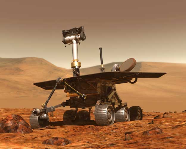
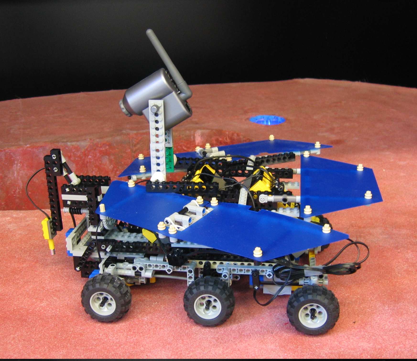
An important question scientists are eager to answer is whether there exists water on the planet Mars. If water is present, perhaps also life is possible on the red planet. In 1997, the first NASA probe landed on Mars. In January 2004, two Mars exploration rovers landed on the Martian globe [1]. The golf cart-sized rovers were autonomous, robotic dune buggies that carried their own science, power and communications equipment. Since January 2004, several experiments and measurements have been performed which indicate that water had been around on the planet for a while. In August 2005, a third exploration rover was sent to Mars, this rover will join Mars Global Surveyor and Odyssey in their exploration of the planet. In the upcoming years, more inquisitive spacecrafts will follow them to investigate Mars, perhaps solving the mystery of what happened to the planet’s water and preparing for the arrival of the ultimate scientific explorers: humans [1]. In the Dynamics and Control Laboratory (WH -1.13) a reproduction of the Mars exploration rover is present. This reproduction is made out of LEGO, especially using LEGO Mindstorms, as shown in Fig. 1.1. The Mars-rover is equipped with two programmable interfaces (LEGO RCX 2.0), a camera, three light sensors, two motors, two encoders and a temperature sensor.
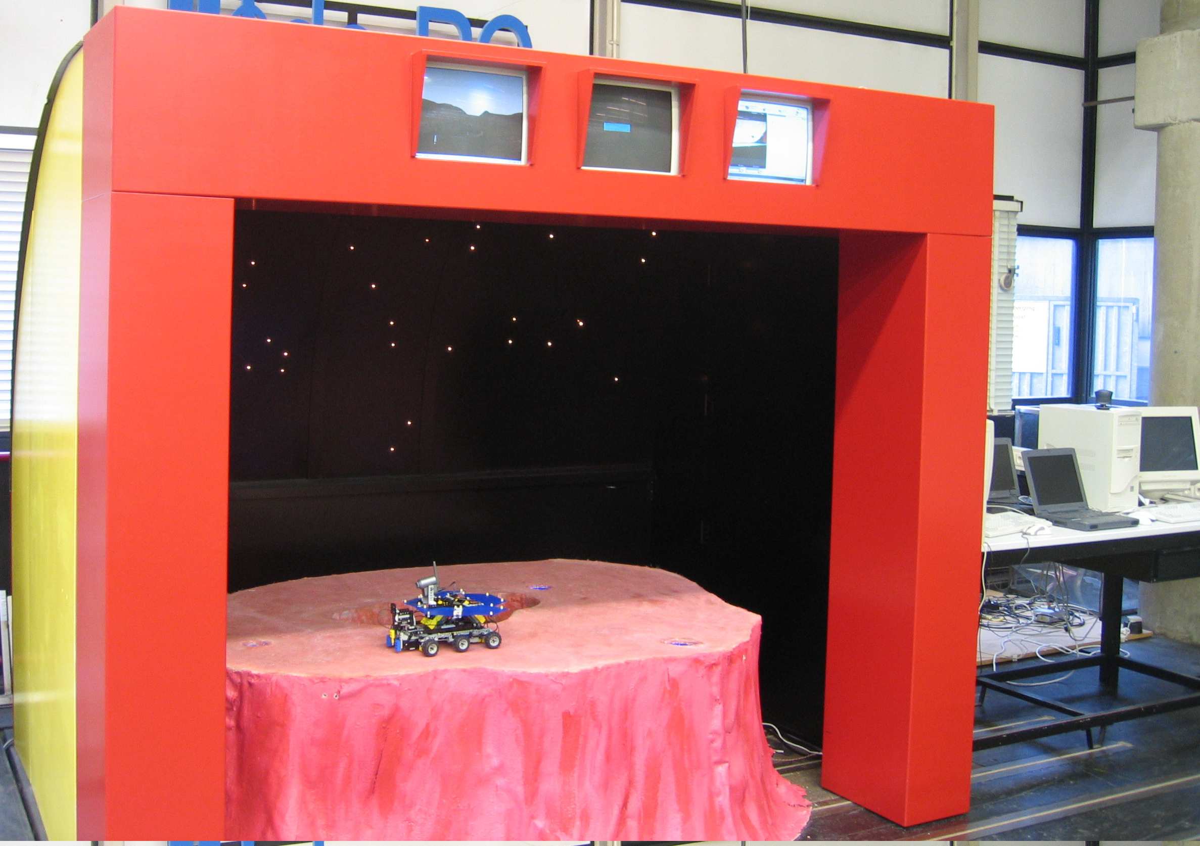
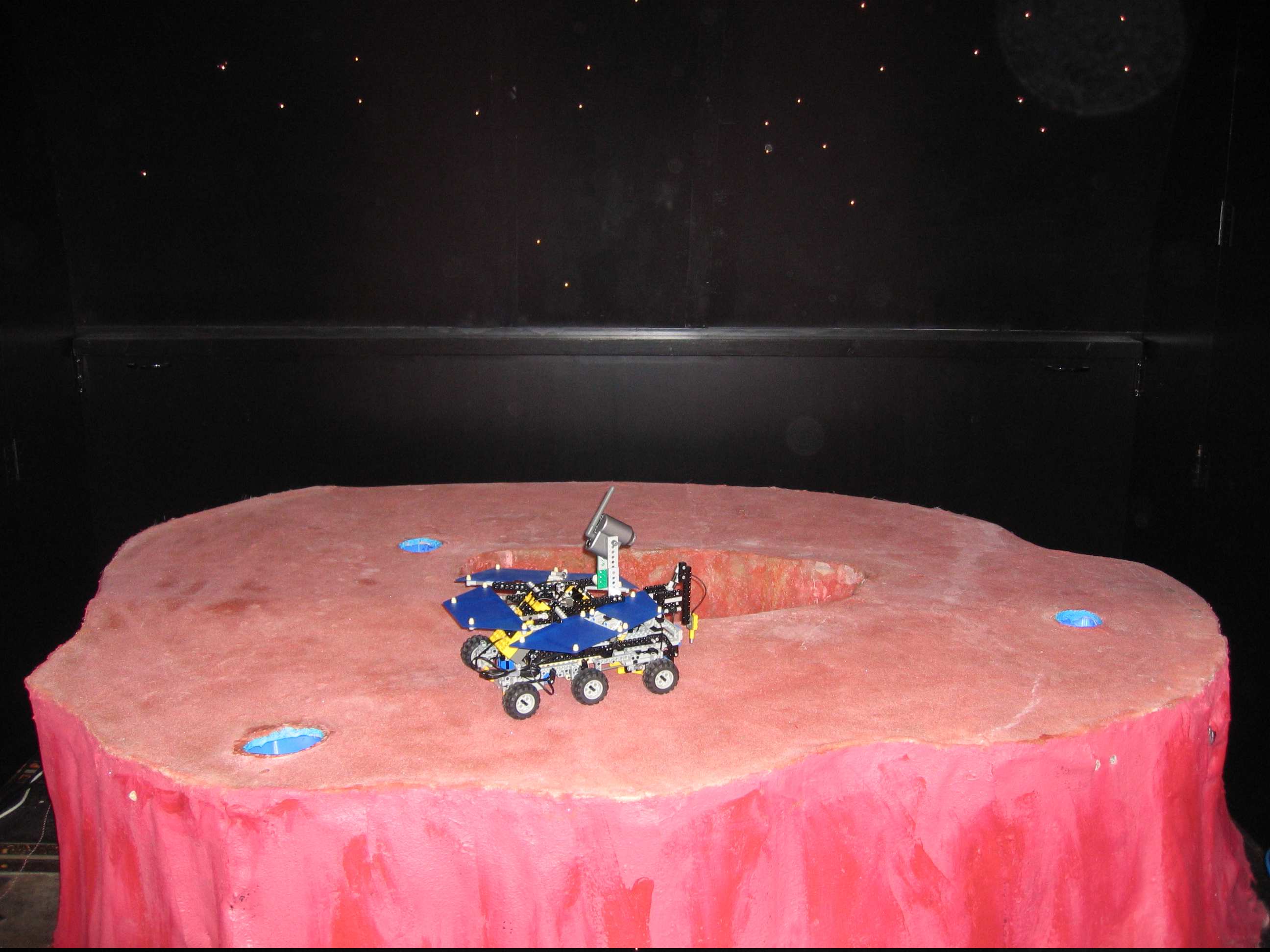
The LEGO Mars-rover is located on a Mars landscape containing three lakes as shown in Fig. 1.2. Now it has been established that water existed on Mars, the next mission is to find the locations of this water and to discover its properties. In this course this is done by determining the temperature of the water in the three lakes of the landscape. However, no software is present on the programmable interfaces of the Mars-rover. This software has to be designed and developed during the course in order to complete the mission. The earth computer can upload programs to the programmable interfaces of the Mars-rover. The interfaces can send and receive data to and from the earth computer. The programs are written in C using the BrickOS environment.
The course will consist of lectures and workshops which will introduce you in the interesting world of embedded motion control. The mission will be performed by groups of 4 people which will be assigned a group tutor. Each group will have weekly meetings with the tutor regarding questions about the mission. Four weeks after the beginning of the course each group will present their software design to the other groups. At the end of the course a final contest will be held where all groups have to perform the mission. Every group also has to deliver a website-as-report, which describes the complete embedded motion design, including an evaluation of the obtained results.
Goal
The general setting of the Mars-mission has been described in the introduction. The overall goal of the Mars-mission can be described as
- Program the Mars-rover in order to find out if there exists water on Mars. If water is found perform measurements to find out its state.
A description which is more applicable to the course and the setup as shown in Fig. 2.1 is
- Write software for the Mars-rover such that it finds the three lakes, measures the temperature of the water and sends the outcome to the earth computer.
This goal can be divided into several subgoals
- Getting familiar with the LEGO working environment.
- Learn the C programming language.
- Design of the software architecture.
- Programming of the mission software.
- Completion of the mission.
At the end of the course the Mars-mission will be performed by all groups in a final contest.
Hardware
In this chapter the different LEGO parts are discussed in more detail.
RCX
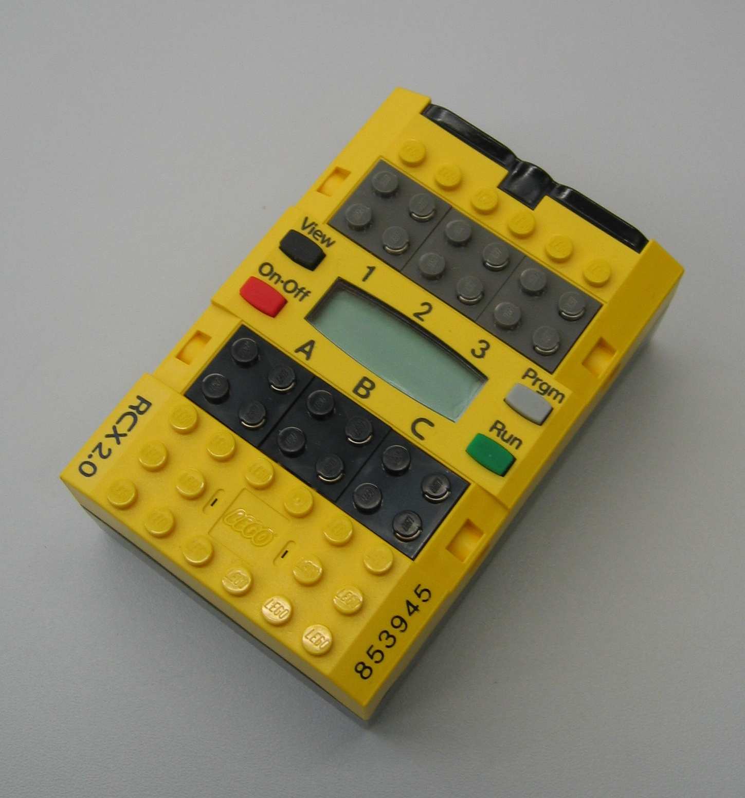
The RCX contains a CPU, display, memory, three actuator output ports and three sensor input ports. The output ports (A, B and C) can be operated in three modes: on, off or floating. When an output is turned on, it can run either in a forward or reverse direction. The output power level can be adjusted using pulse width modulation (PWM). The sensor ports (1, 2 and 3) can be used for both passive and active (powered) sensors. What kind of sensor is used has to be told to the RCX by a program. For each sensor, the sensor type and sensor mode have to be configured. The sensor type defines the interaction. The sensor mode determines the interpretation of the sensor values. The LCD can display four-digit signed numbers, single-digit unsigned numbers and special indicators. The RCX can communicate with a computer or another RCX through infrared. The RCX is powered by six AA batteries.
Temperature sensor
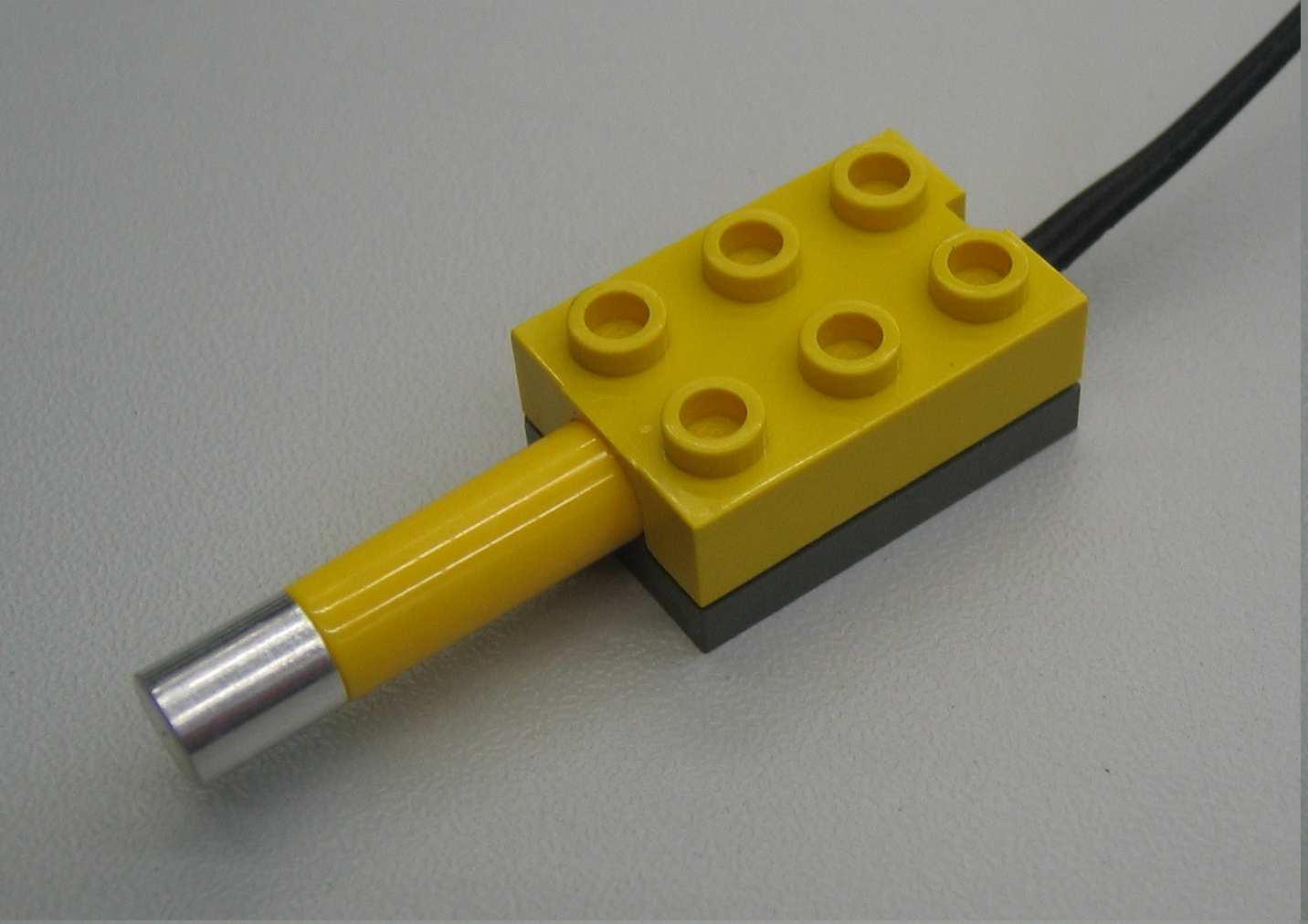
The LEGO temperature sensor measures using a thermistor (temperature sensitive resistor), i.e. the resistance of the thermistor changes with temperature. The resistance is measured by a circuit and converted to a temperature. It is a passive analog sensor. The temperature sensor is calibrated from -20° Celsius to +50° Celsius. The RCX can read and display the temperature in either Fahrenheit or Celsius.
Light sensor
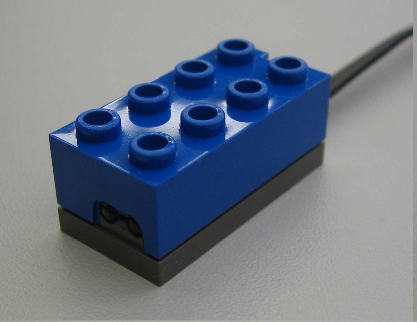
The light sensor is an active sensor used to detect the amount of lightness and darkness. When the sensor is pointed at a surface, it reads the amount of reflected light. A light surface or a bright light results in a higher value than a black surface or shadowed object. It can also respond to blinking objects. The light sensor both emits and detects light. Therefore it can measure the amount of light in a room or the reflected amount of light from a surface. The light sensor can be used for line detection, edge detection or light/dark seeking purposes. In this course the light sensor will be used for edge detection.
Rotation sensor
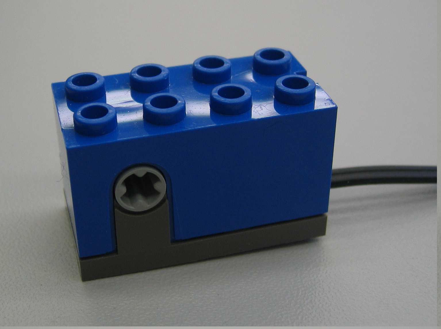
The rotation sensor measures rotation with a resolution of 16 increments per revolution. The sensor uses two light diodes and an encoder disc with 4 slots which results in a quadrature signal with the mentioned resolution of 16 inc/rev. The resolution can be altered by applying a transmission between the motor and the rotation sensor. The maximum working speed of the rotation sensor equals 500 RPM. Note that at very low or very high speeds it is possible that counts are missed.
Motor
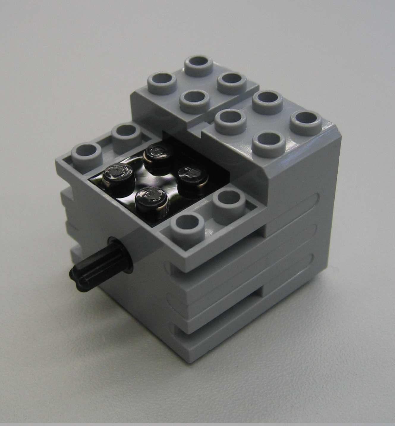
The motor has an internal five-stages gear reduction to increase the torque and a weight of 28 g. If no load is attached to the motor, the rotational speed equals 340 RPM and the no-load current equals 3.5 mA [2]. The rotation speed of the motor is proportional to the voltage applied to it. The stall torque (locked motor axle shaft) of the motor equals 5.5 Ncm, the stall current equals 340 mA. Despite of the presence of an internal thermistor, avoid long stall periods in order to prevent overheating of the motor [2].
USB IR tower
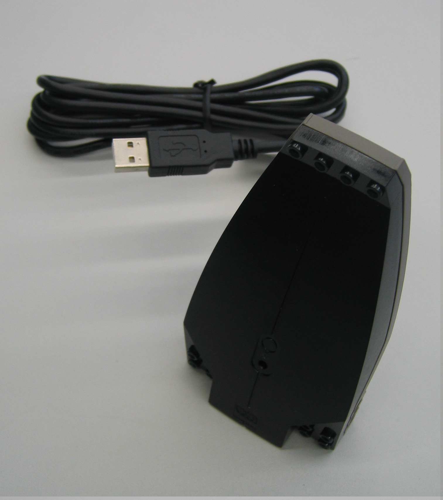
The RCX communicates to a computer through IR light. To receive the signals from the RCX, the USB IR tower can be used. For computers which already have an IR port, still the tower has to be used. Most standard IR ports use IrDA for communication, while the RCX uses a simpler proprietary protocol. The IR tower programs can be used to download control programs to the RCX and to upload data to the computer. The IR tower and the RCX must face each other to establish communication.
Connecting wire
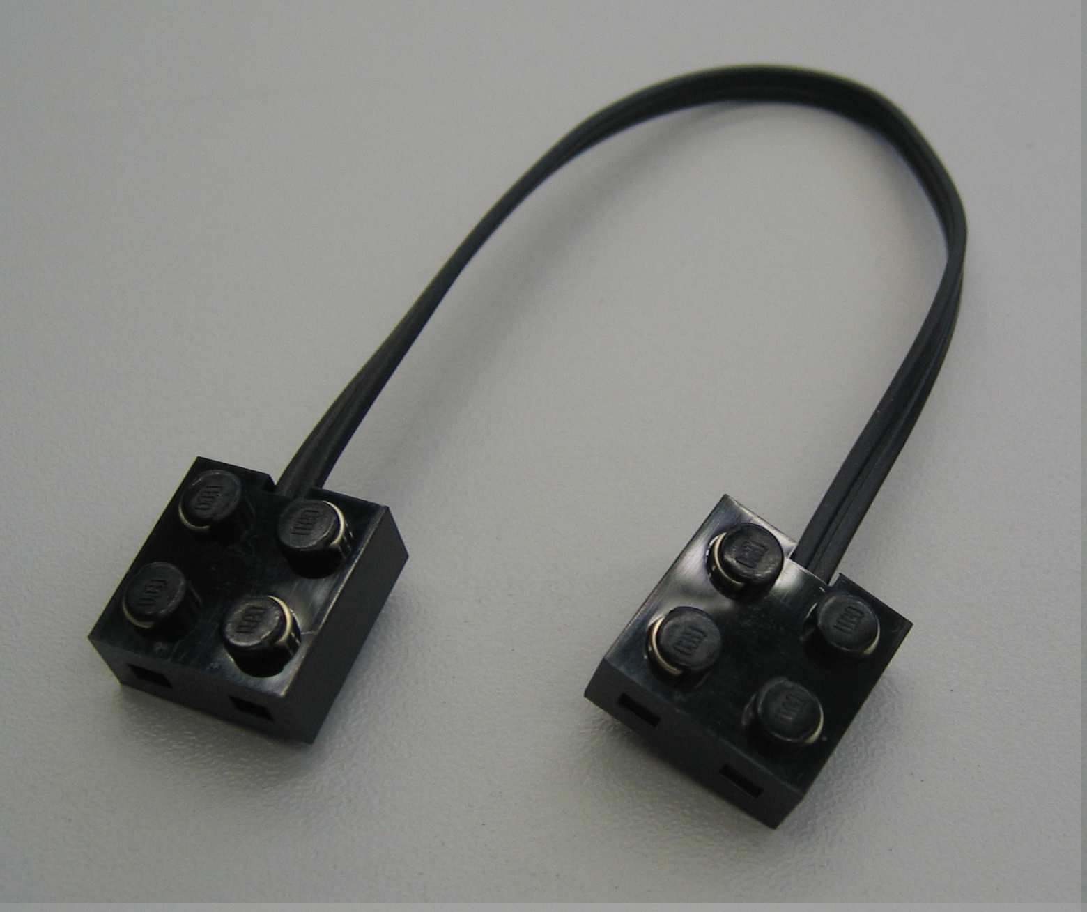
The connecting wire can be used to connect the motor to the RCX or to extend the connection wires of the various LEGO parts. No specific orientation of the connectors is required.
Installation
This document describes how to the install the necessary and sufficient software to start programming your own RCX from LEGO Mindstorms to control your Marslander. After reading this small manual, you should be able to run your own program on the RCX.
Installing Ubuntu 10.04 LTS
Ubuntu can be installed according 2 methods
- Using an USB stick.
- Using the hard drive.
For both methods the most recent installation instructions can be found on http://www.ubuntu.com/desktop/get-ubuntu/download. Make sure that you download the appropriate architecture ie. 32 or 64-bit. Creating a dual-boot system, ie. installing Ubuntu on the hard drive is the most convenient. When installing Ubuntu on an USB stick make sure to use some persistence/extra space during the install such that information is still there after a reboot.
If you installed Ubuntu on an USB stick you have to make sure that your notebook will boot from the USB stick. This can be edited in the BIOS or for most notebooks during the booting process, F9 can be pressed to select the USB drive.
Installing the packages
Download the packages
First the following packages need to be downloaded
- brickos 32-bit, 64-bit.
- binutils-h8300-hms 32-bit, 64-bit.
- gcc-h83000-hms 32-bit, 64-bit.
- brickos-doc Download.
The main page can be found at http://packages.ubuntu.com/hardy/brickos.
Installing the packages
After all the files are download the installation is as easy as in Windows.
- Double-click the package.
- Click
install package. - After the package is installed it can be closed.
Now a directory can be created for the project files for example /home/ubuntu/emc. Note that the /home/<user> is the same as the user directory in Windows.
Open the terminal, this can be found in Applications->Accessoires->Terminal. In the terminal do the following
ubuntu@ubuntu~$: cd ~
ubuntu@ubuntu~$: mkdir emc
ubuntu@ubuntu~$: cd emc
ubuntu@ubuntu~$: cp -r /usr/share/doc/brickos/examples/demo demo
The first line changes the directory (cd) to the home folder. Then the directory emc is created. Finally the demo directory is copied from the documentation directory.
Installing the USB IR tower
First plug in the USB IR tower. To make sure you have permission to use the tower type in the terminal
ubuntu@ubuntu:~$ sudo chmod 666 /dev/usb/legousbtower0
You may test the tower with a simple
ubuntu@ubuntu:~$ echo test > /dev/usb/legousbtower0
The green LED on the tower should light for a second.
Now everything is ready to use.
REMARK: Do not put your computer on standby (hibernate not tested). It seems that a program, compiled by a computer that was waked from standby is causing the brick to crash. To avoid this just turn off your computer instead of standby/hibernate.
Putting a kernel into the RCX
In order for the RCX to be able to run your programs, it needs to be provided with dedicated firmware. The RCX is equipped with a ROM chip on which the standard Mindstorms firmware is stored. Every time the RCX loses power (e.g. when changing batteries), the firmware which was running on the RCX is replaced by this standard firmware. Therefore, every time the RCX has lost power, the dedicated firmware has to be installed again.
N.B.: If there is already a kernel running on the RCX (not the original one), then this one has to be deleted before a new one can be transferred to it. This can be done by pushing the Prgm button immediately after you push the On-Off button to swith the RCX off (this may take some practice).
To install the firmware for BrickOS, power on your RCX, open the terminal and type
ubuntu@ubuntu:~$ firmdl3 --tty=/dev/usb/legousbtower0 /usr/lib/brickos/brickOS.srec
Now the kernel is being transferred to the RCX and when this is finished, your RCX is ready to be programmed with your own programs.
Downloading your program to the RCX
The programming language used to control the RCX is C. Suppose you wrote a program in C to display "hello world" on the LCD of the RCX. This simple file helloworld.c can be found in the demo directory ~/emc/demo. In order to compile this code we use the command make. This command uses the Makefile already present in the same directory. Therefore, all your C-code should be put into that directory. To compile type
ubuntu@ubuntu:~/emc/demo$ make helloworld.lx
This will start the compilation process and delivers (amongst others) the file helloworld.lx. This is the actual program that will run on the RCX. To download it to the RCX, type
ubuntu@ubuntu:~/emc/demo$ dll --tty=/dev/usb/legousbtower0 helloworld.lx -p1
where the option -pX is used to specify the program number on the RCX, here number 1 (there is room for 7 different programs, hence X is in the range 1 to 7). The program is now loaded on the RCX and by hitting the run button, the text hello world will be displayed on the screen.
If you want the tty part out in the future you may define a local variable by typing
export RCXTTY=/dev/usb/legousbtower0
However when opening a new terminal the local variable does not exist anymore. Therefore it might be convenient to add the line to your .bashrc. Do this by typing
ubuntu@ubuntu:~$ gedit ~/.bashrc
The application gedit will now open, add the line add the bottom of the file, save and close.
Now a second program which plays sound (sound.c) can be compiled and downloaded to the RCX by typing
ubuntu@ubuntu:~/emc/demo$ make sound.lx
ubuntu@ubuntu:~/emc/demo$ dll sound.lx -p3
You can now switch between these two programs (1 & 3) using the Prgm button on the RCX.
Libraries
In this chapter the libraries processing of the vision information are described and needed for communication. The startup procedure of the earth computer is also included in this chapter.
Video processing on the earth station
To navigate through the unknown mars landscape, vision information plays an important role. By using vision information, the positions of the lakes are determined which are in the field of view. This information can be used as input to determine the trajectory of the mars-lander. Due to the limited onboard computational power of the Mars-lander, the main part of localizing the lakes is done by video processing on the earth-computer. The video processing is based on both color and dimensions of the lakes in the captured images. The centers of the lakes is determined in terms of pixels and linked to the sender which communicates with the Mars-rover. Fig. 5.1 roughly represents the structure of the image processing. Especially if unexpected output is given by the vision system, it can be useful to roughly understand the main steps of the vision module.

The main steps will be described shortly in the remainder of this section.
- Acquisition: The image is acquired by the standard acquisition block of Matlab which can run at several sample frequencies. The output of the camera is given as three matrices: Red, Green and Blue, where each matrix exists of 240 × 320 pixels. It has to be emphasized that the pixels are numbered starting in the left-upper corner as indicated in Fig. 5.2.
- Color segmentation: Due to the distinct colors of the mars landscape, the objects in the mars environment can be separated based on color information. Every pixel has three [R,G,B] color values between 0 and 255 (short int). This could be interpreted as a location in the 3-D RGB color space. By defining bounds in the color-space, one is able to test for a certain color. To be robust for lightning conditions, these bound are chosen rather loosely. One should keep in mind that all objects in the background which appear more or less blue could disturb the image processing as they may appear as possible lakes.
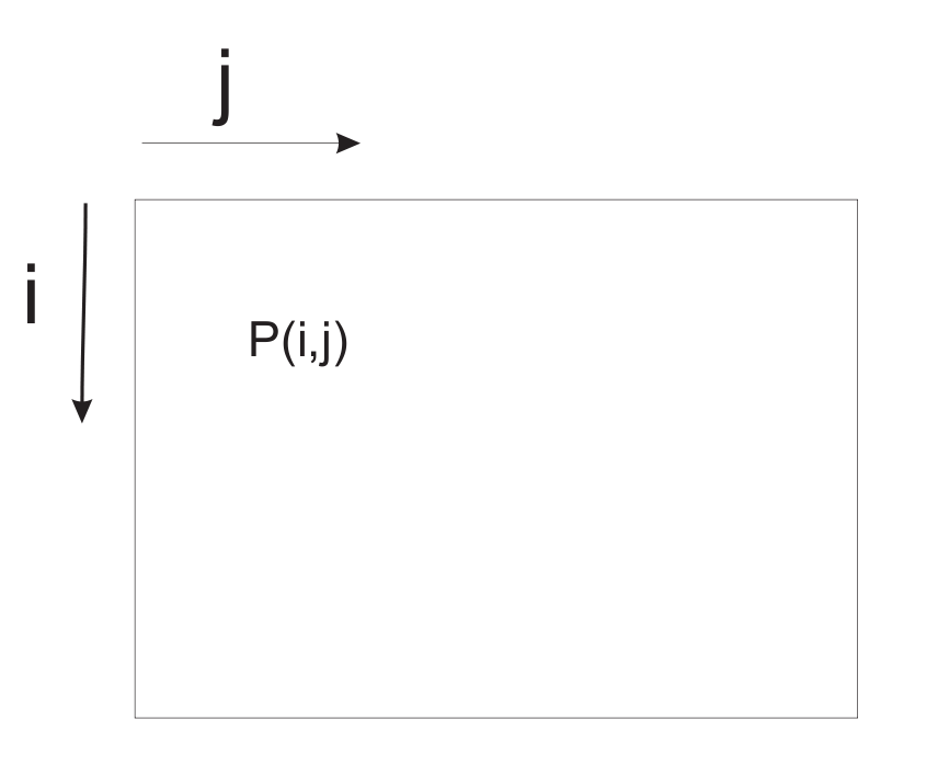
Figure 5.2: Definition of pixel numbering - Blob-analysis and selection: Blob-analysis is used to search for regions of dense blue pixels. The outer bounding box of the blobs and its center are given as output. Since a high number of candidate blobs can be given as output, also a geometric check is performed based on the relation between the height and the length of the blob in relation to the distance. This check is based on geometric relations where the dimensions of the lakes are transformed into a height and width in the image of the camera. The angle of the camera with respect to the ground is one of the key parameters in this relation. In order to perform well, the angle of the camera with respect to the ground should be set properly. Fig. 5.3 depicts how the angle of the camera should be set. The candidate blobs that fulfil the conditions are given as output for the positions of the lakes and are given to the infrared sender. The structure is as follows: [math]\displaystyle{ \begin{bmatrix} \text{row } i \text{ of first lake}, & \text{row } i \text{ of second lake}, & \text{row } i \text{ of third lake} \\ \text{column } j \text{ of first lake}, & \text{column } j \text{ of second lake}, & \text{column } j \text{ of third lake} \end{bmatrix}. }[/math]
- Most of the time only one lake is found, or two in rare cases. If the corresponding lake is not found, zero is given as output for the second and for the third lake respectively.
Starting the earth computer
The earth computer can be started in the following steps.
- Convince yourself from the fact that the camera is powered on and the camera receiver is connected to the pc.
- Start the program GrandTec Walkguard from the start menu. If the camera is connected properly, the camera image appears. Since the color segmentation proces depends heavily on the settings of the camera, these parameters have to be set. In the program GrandTec Walkguard, go to the Tab:
Video. Set the following values:- Brightness: 149
- Contrast: 174
- Saturation: 191
- Hue: 143
- Note that these values are a guideline. Since the values depend on lighting conditions some can deviate from these values. It is possible that the setting of the camera parameters has to be repeated if the camera has been disconnected from the power-plug.
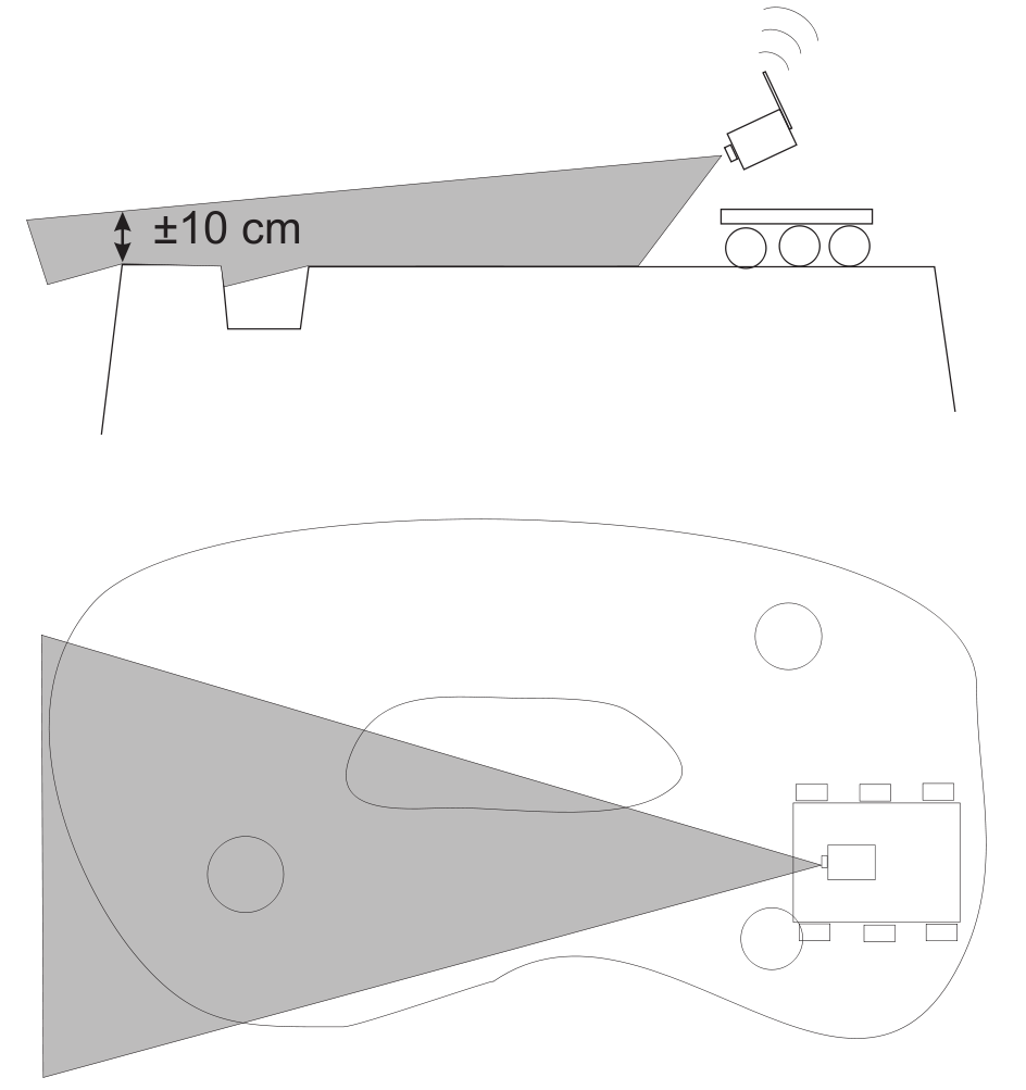
Figure 5.3: Setting the angle of the camera
- In order to properly check the geometry of the lakes, the camera should have the right angle with respect to the underground (see Fig. 5.3). Adjust the angle of the camera according to this figure. Exit the program GrandTec Walkguard.
- Color calibration (not needed, or done by tutors).
- Start Matlab and go to the directory
D:\MC\vision. Open the Simulink model filecommunication_and_vision_with_viewers.mdl. In order to guarantee best performance, the priority of Matlab can be increased. Press:Ctrl+Alt+Del, go toTask Manager,processes, right-click matlab.exe. Go toSet Priorityand setReal-time. Note that several Simulink schemes are available. If problems occur which could be due to the vision processing: one could chose to run the program:vision_with_viewerto get
more info about the color-classification. Start the Simulink scheme.
Communication
LegOS Network Protocol (LNP), which is included in the BrickOS Kernel, allows for communication between BrickOS powered robots and host computers. The communication is realized by the infrared ports. Therefore, first of all make sure that there are no obstacles between two communicating RCX bricks to prevent communication errors. For the purpose of this course there have been made adjustments and modifications in order to make the communication between RCX bricks and between RCX bricks and the host computer a lot easier.
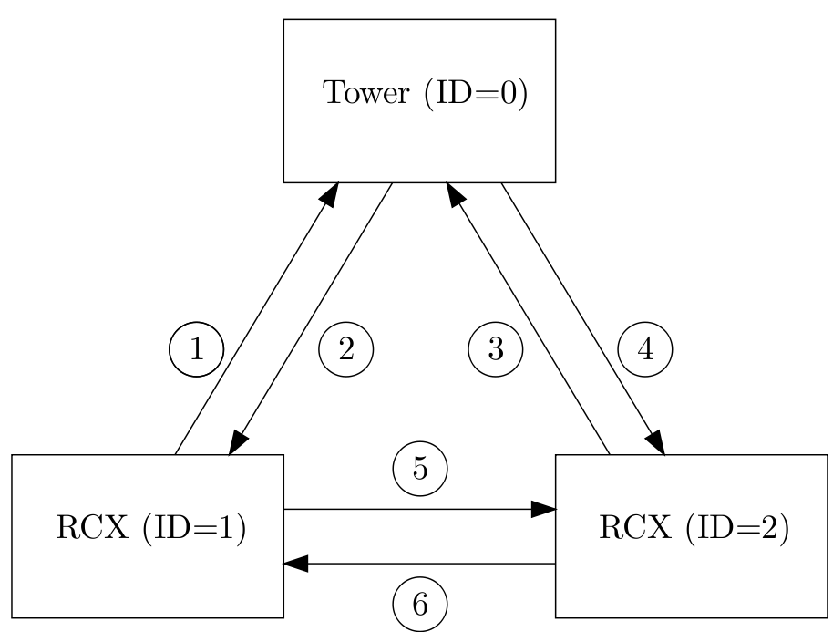
A possible configuration of a communication setup is depicted in Fig. 5.4. It contains two RCX bricks and one host computer equipped with the Lego USB Tower. Each client has its own iden- tification number. The host computer is identified by ID = 0. The two RCX bricks are identified by ID = 1 and ID = 2. In the main C-file this ID should be defined, for example
#define ID 1
for RCX brick one. Next, the C-file com.c should be included using
#include "com.c".
Make sure that you first define the ID before you include com.c. The C-file com.c is makes it possible to send and receive integers or arrays of integers. The main functions in this file are called com_send and read_from_ir. The source code of the C-file com.c can be found here by choosing Lets Talk. The corresponding lecture can be found under the subsection Lecture Slides
com_send
The main function to send integers is com_send.
Syntax
int com_send(int IDs, int IDr, int message_type, int *message)
Arguments
IDs:The ID of the sender IDr:The ID of the receiver message_type:The message type message:Pointer to an integer or an array of integers
Description
Call com_send to send an integer from the sender with ID = IDs to the receiver with ID = IDr. The message that has been send has a message type. There are seven message types: 1 to 7. Each message type is coupled to a global variable:
- Message type 1:
TRIGGER1(integer) - Message type 2:
TRIGGER2(integer) - Message type 3:
TRIGGER3(integer) - Message type 4:
TRIGGER4(integer) - Message type 5:
TRIGGER5(integer) - Message type 6:
TEMPERATURE(integer) - Message type 7:
COORDINATES(array of 6 integers)
These global variables can be read in all your functions, for example by calling TRIGGER1. Sending an integer with message type 1 will result in the adjustment of the global variable TRIGGER1 at the receiver side.
Examples
/* declare and initalize a */
int a = 1;
/* examples of sending messages */
com_send(1,0,7,&a);
com_send(2,0,7,&a);
com_send(1,2,1,&a);
com_send(2,1,1,&a);
The communication in the example correspond with line 1,3, 5 and 6 respectively. A description of the communication lines is shown in Fig. 5.4. At communication line 1, the RCX with ID = 1 asks the coordinates from ”earth”. The coordinates are returned at communication line 2 and are stored in the variable COORDINATES. At communication line 3 RCX with ID = 2 asks the coordinates from ”earth”. The coordinates are returned at communication line 4 and are stored in the variable COORDINATES. The coordinates correspond to the pixel numbering of Fig. 5.2. To read the coordinates simple call COORDINATES[0] for the first coordinate, which is the i-coordinate of the lake that is most nearby. An i-coordinates of 0 means that the center of this lake is seen at the top of screen of the camera. An i-coordinate of 240 means that the center of this lake is seen at the bottom of the screen of the camera. COORDINATES[1] is the j-coordinate of the lake that is most nearby. An j-coordinate of 0 means that the center of this lake is seen at outer left side of the screen of the camera. An j-coordinate of 320 means that the lake is seen at the outer right side of the screen of camera. So the screen can be compared with a matrix with a size of 240 × 320. The element (0,0) is the upper left element of the screen / matrix. The element (240,320) is the bottom right element. A lake is found when the following relations are satisfies 0 < i-coordinate < 240 and 0 < j-coordinate < 320. COORDINATES[2] and COORDINATES[3] represent the i- and j-coordinates of the second lake. Finally COORDINATES[4] and COORDINATES[5] represent the i- and j-coordinates of the lake that is located most far away. At communication line 5, the RCX with ID = 1 sends TRIGGER1=1 to RCX with ID = 2. The opposite is the case at communication line 6.
read_from_ir
To use the function read_from_ir, a thread (see [3], page 169) should be started. The task of this
thread is to constantly detect whether or not a message is received at the infrared port. If a message
is received, the variables TRIGGER1, TRIGGER2, TRIGGER3, TRIGGER4, TRIGGER5, TEMPERATURE
and COORDINATES are adjusted depending on the message type. To start the thread, first define
the thread identification like
/* declare thread id for read_from_ir_thread */
tid_t read_from_ir_thread;
To start the thread your main file should look like:
/* begin main */
int main(int argc, char *argv[]) {
	/* initialize communication port */
	lnp_integrity_set_handler(port_handler);
	/* set ir range to "far" */
	lnp_logical_range(1);
	/* initialize semaphore for communication */
	sem_init(sem_com, 0, 1);
	/* start read_from_ir thread */
	read_from_ir_thread = execi(&read_from_ir,0,0,PRIO_NORMAL,DEFAULT_STACK_SIZE);
	/* return 0 */
	return 0;
/* end main */
}
In the function lnp_integrity_set_handler the porthandler is defined. If a message is received, the porthandler defines what to do with this message. The function lnp_logical_range is used to set the infrared range of the RCX brick to ”far” in order to communicate over a long range (± 5 m). To prevent that two or more threads are writing the variables TRIGGER1, TRIGGER2, TRIGGER3, TRIGGER4, TRIGGER5, TEMPERATURE, COORDINATES at the same time, semaphores are used (see [4], chapter 6). For example, if another RCX brick is sending a message to adjust the variable TRIGGER1 and a thread running on this RCX brick is adjusting the variable TRIGGER1 at the same time. The function sem_init(sem_com) initializes the semaphore sem_com to one. So if you want to change one of the variables TRIGGER1, TRIGGER2, TRIGGER3, TRIGGER4, TRIGGER5, TEMPERATURE, COORDINATES, semaphores should used. Therefore you cannot simply write
TRIGGER=0;
but instead it should be
sem_wait(sem_com);
TRIGGER=0;
sem_post(sem_com);
Earth Station
The following is tested on Windows XP and Matlab R2007a (Martijn Maassen).
The CD can be obtained here.
Usage for tutors only! Everything is already installed for the Embedded Motion Control course.
Installation earth computer
- Open autorun.exe from cd and install the following
- Install Grand WalkGuard Ver. 1.9.
- Install Grand Remote Camera Ver. 1.9.
- USB Driver Installation.
- Connect camera to computer.
- Open Start Menu->Programs->GrandTec->Grand WalkGuard->WalkGuard.
- Adjust the settings according to here.
- Close WalkGuard program.
- Connect Lego IR tower USB, do not let Windows automatically install driver but use drivers from the IR_Tower_USB folder on the CD.
- Copy the matlab vision files; copy the folder
EMCfrom the CD to the D-drive on the computer (D:\EMC). Stick to this location becausecom_host.cincludesD:EMC_Communication_Host\rcxdll. - Run
D:\EMC\Vision\Vision Driver\WINXP2k\DPInst.exeand install the driver. - Open Matlab, go to
D:\EMC\Visionand runmex_all_files.m(mex files will be created). - Open the Simulink file
vision_and_communication_with_viewers.mdland run it. If an error occurs during opening of the Simulink file, try to remove the camera (USB) before starting the Simulink file. Plug in the camera and then try to run the Simulink file again.
Additional information
Tips and tricks
- When experimenting with the additional mars-rovers, the RCX from the experimental kit can be used to fulfil the role of the earth computer.
- First make a sketch of the software architecture on paper before writing the actual code.
- Make a clear distinction between the sample rates of the different software parts and thoroughly consider on which RCX they are implemented.
- If operations fail, printing error code to the LCD can help to debug the program.
- In order to compile the written C-programs into .lx-files, all C-code should be put into the directory where the
Makefileis present, i.e.~/emc/demo. - To prevent the system from crashing it is necessary to insert a stop thread in the program in which all other threads are killed.
- Avoid the use of
while(1), usewhile(!shutdown_requested())instead. - Make sure that variables do not overflow, for example keep an integer smaller than 32767 (see [1, page 187])
- The lake may not be visible when standing right in front of it.
- To get wireless internet at the TU/e go here
- Dropbox is a nice application/service to share the code.
- Please make sure that when booting ubuntu from a usb-drive, you do NOT put the system on standby or hibernate! There have been several persons for whom this led to an un-bootable ubuntu drive.
Common Issues
Please add any more known issues to this list!
- My brick doesn't behave as expected / hangs / or won't stop
- Shutdown the brick by taking one of it's batteries out. Press the on/off button once to make sure the power is lost and put the battery back in again. Now you have to reload the firmware and improve your programming skills ;)
- Uploading new firmware fails every time
- Before uploading new firmware, take out one of the batteries. Press the on/off button once to make sure the power is lost and put the battery back in again. Now you have to reload the firmware.
- When running my program, the man starts running but the program does nothing at all. When pressing run again the brick stops, but my program does nothing.
- This probably has to do something with the memory of the brick. Especially when one or more large programs are present on the brick, this symptom occurs. When testing larger programs, make sure to use only one program slot and overwrite your program every time.
- When trying to upload a program, the infrared icon flashes fast and the upload fails
- Make sure there is no direct sunlight shining into the brick and/or tower. Also try switching the brick on and off and start uploading again.
Application Programming Interface
The API can be downloaded here
Building plan
The building plan can be downloaded here
Lecture slides / Workshops
EMC_Workshop_Sense_And_Act.pdf
EMC_Workshop_Lets_Talk.pdf
EMC_Course_Multitasking_Synchronisation.pdf
Group Blogs
Year 2011
Group 01 - Visit Blog - Bart, Maarten, Stijn, Swan
Group 02 - Visit Blog - Serhat, Sergiy, Sultan, George, Robin
Group 03 - Visit Blog - Ron, Peter, Albert, Jan
Group 04 - Visit Blog - Dennis, Jos, Micha, Matthijs, John
Group 05 - Visit Blog Arjo, Jordan, Ferry, Lazlo
Group 06 - Visit Blog - Bernadette, Arne, Geert-Jan, Erik, Freek
Group 07 - Visit Blog - Rob, Rene, Rico, Pave, Nick
Group 08 - Visit Blog - Juan Camilo, Muhammad, Faran Ahmed, Handian, Haixu
Group 09 - Visit Blog - Edward, Marcel, Rene, Mirjam, Jacqueline
References
- ↑ 1.0 1.1 Editor: Dennis Armstrong NASA Official: Brian Dunbar. Demystifying Mars. National Aeronautics and Space Administration (NASA). http://www.nasa.gov/missions/highlights/demystifying_mars_1.html.
- ↑ 2.0 2.1 Philippe Hurbain. Philo’s Home Page: LEGO Mindstorms. http://philohome.com/.
- ↑ D. Baum, M. Gasperi, R. Hempel, and L. Villa. Extreme MINDSTORMS. Apress, 2000. ISBN 1-893115-84-4.
- ↑ Q. Li and C. Yao. Real-Time Concepts for Embedded Systems. CMP Books, 2003. ISBN 1-57820-124-1.