Retake Embedded Motion Control 2018 Nr2: Difference between revisions
| (55 intermediate revisions by the same user not shown) | |||
| Line 1: | Line 1: | ||
= Student = | |||
{| border="1" cellpadding="5" cellspacing="1" style="float:center;" | |||
! TU/e Number | |||
! Name | |||
! E-mail | |||
|- | |||
| 1036818 | |||
| Rokesh Gajapathy | |||
| r.gajapathy@student.tue.nl | |||
|- | |||
|} | |||
= Introduction and Problem Definition = | = Introduction and Problem Definition = | ||
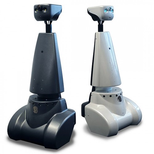
[[File:Gostai-Jazz-500x500.jpg|thumb|left|Figure 1: PICO]] | [[File:Gostai-Jazz-500x500.jpg|thumb|left|Figure 1: PICO]] | ||
| Line 11: | Line 24: | ||
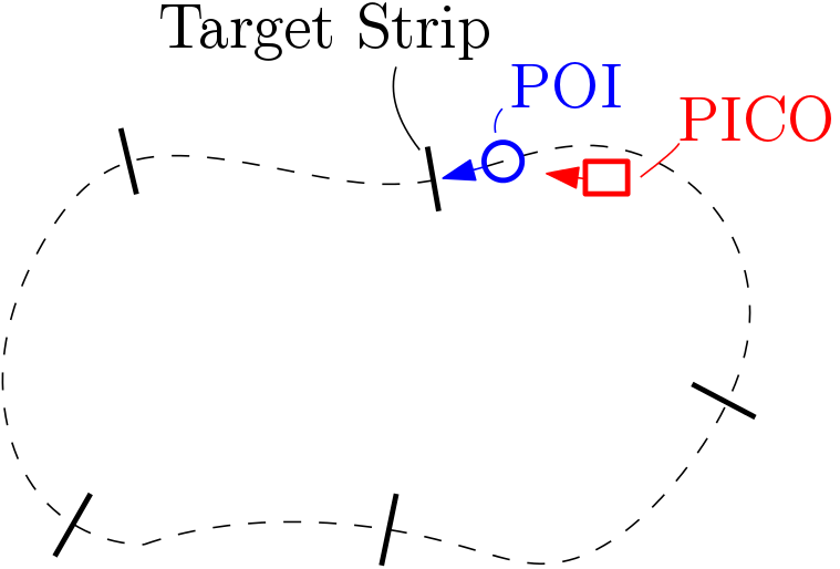
[[File:Path.png|size=small|thumb|400px||center|Figure 3: A sketch of the setup. The pre-defined path is indicated by the dashed lines, the target strips by the black lines perpendicular to the pre-defined path, the POI that follows the pre-defined path in blue, and PICO in red.]] | [[File:Path.png|size=small|thumb|400px||center|Figure 3: A sketch of the setup. The pre-defined path is indicated by the dashed lines, the target strips by the black lines perpendicular to the pre-defined path, the POI that follows the pre-defined path in blue, and PICO in red.]] | ||
= | |||
{| border="1" cellpadding="5" cellspacing="1" style="float: | = Initial Design = | ||
! | |||
! | The initial design section gives an overview of the various design decisions taken to achieve the desired results. The requirements for completing the task with available resources is defined followed by the state machine and finally functional components required to achieve the state machine defined. | ||
! | |||
== Available Resources == | |||
PICO is a robot with a holonomic base which can move in <math>(x,y,\theta)</math> directions. It consist of encoders which provides the odometery data and a Laser Range Finder (LRF) which provides an array of laser points with its ranges respectively. The output to the PICO is in terms of velocity <math>(\dot{x},\dot{y},\dot{\theta})</math> through the EMC environment. | |||
{| border="1" cellpadding="5" cellspacing="1" style="float:center;" | |||
! Specification | |||
! Value | |||
! Unit | |||
|- | |||
|Detectable Distance | |||
|''0.01'' to ''10'' | |||
|meters [m] | |||
|- | |||
|Scanning Angle | |||
|''-2'' to ''2'' | |||
|radians [rad] | |||
|- | |||
|Angular Resolution | |||
|''0.004004'' | |||
|radians [rad] | |||
|- | |||
|Distance between POI and PICO | |||
|''0.4'' | |||
|meters [m] | |||
|- | |||
|Speed of POI | |||
|''0.5'' | |||
|meter/second [m/s] | |||
|- | |- | ||
| | |Width of target strip | ||
| | |''1'' | ||
| | |meter [m] | ||
|- | |- | ||
|} | |} | ||
< | == Design Decisions == | ||
From the available resources and problem definition important design decisions are taken as follows: | |||
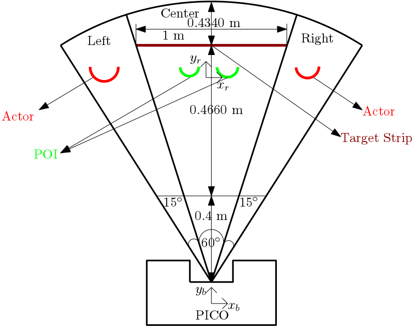
1. The maximum detectable distance and scanning angle is constrained to 1.3 m and 90 degree respectively because the length of the target strip is 1 m, a equilateral triangle is drawn with respect to LRF center which is 60 degree for center, 15 degrees for left and degree right respectively. | |||
2. The reference frame <math>(x_r,y_r)</math> and base frame <math>(x_b,y_b)</math> is defined as POI and PICO respectively. Since PICO need to follow the POI (i.e) go forward or rotate with respect to the POI. | |||
3. The PICO moves at a speed of 0.5 m/s and rotates at 2 rad/s because the POI walks at speed of 0.5 m/s. | |||
4. Stopping distance is 0.4 m (i.e) if the distance between POI and PICO less than 0.4 m PICO stops obtained from the problem statement | |||
5. The delectable sensor range is split into three components left,center and right to tackle the disturbances (i.e) Actors. | |||
[[File:follow_me_1.png|center|size=large|thumb|600px|Figure 4: PICO Design Decisions]] | |||
== Requirements == | |||
{| border="1" cellpadding="5" cellspacing="1" style="float: | {| border="1" cellpadding="5" cellspacing="1" style="float:center;" | ||
! Function | ! Function | ||
! | ! Action | ||
! Validation | ! Validation | ||
|- | |- | ||
| | | Identify the POI (reference frame) | ||
| | | Two legs are identified which is close to PICO (base frame) | ||
| | | Visualize using lase range points, see | ||
|- | |- | ||
| | | Follow the POI | ||
| | | Follow the POI at a distance of 0.4 m at a speed of 0.5 m/s | ||
| | | Walk straight in-front of the PICO | ||
|- | |- | ||
| Rotate with respect to POI | |||
| Base frame (PICO) rotates with respect to the reference frame (POI) at 2 rad/s | |||
| Walk right and left side in-front of the PICO | |||
|- | |||
| Stop when POI stops | |||
| PICO stops when the distance between POI and PICO less than 0.4 m | |||
| Stop while walking in-front of PICO | |||
|- | |||
| Stop when POI stops | |||
| PICO stops when the distance between POI and PICO less than 0.4 m | |||
| Stop while walking in-front of PICO | |||
|- | |||
| Do not follow the Actors | |||
| Scanning Angle is constrained to 60 degree and if legs are identified in the right or left side of the PICO, it follows the one in center. | |||
| Actors walk on the side of the robot not in between the PICO and POI | |||
|- | |- | ||
|} | |} | ||
== Finite State Machine == | |||
[[File:Stateflow_followme.PNG|center|size=large|thumb|800px|Figure 5: State Flow Diagram]] | |||
== Software Architecture == | |||
The '''Task Software Architecture''' is preferred to achieve the goal of following the POI with actors in the environment because this architecture handles both continuous and discrete events. This architecture consist of the following components: | |||
<b> Perception (Continuous): </b> | |||
The perception class obtains the laser range data from the world model class and process the laser data in order to find the POI position in real-time. And also to find the actors who move around the PICO. | |||
<b> Monitoring (Discrete): </b> | |||
The monitoring class obtains the perception output from the world model and defines the present state of the robot. The monitoring states here are POI not found, POI found, Actor in left and Actor in right. | |||
<b> Plan (Discrete): </b> | |||
The plan class obtains the monitoring output states from the world model class and defines the next action to be taken by the PICO. The plan states are Stop and Follow POI | |||
<b> Control(Continuous): </b> | |||
The control actions obtains the plan state output from the world model class and provides the velocity command to each co-ordinate respectively, such as stop, move forward, rotate right and rotate left | |||
<b> World Model: </b> | |||
The world model consist of all the states and continuous variables which is obtained from perception, monitoring, plan and control functions at every iteration. | |||
The complete cycle runs at the rate of 20 Hz (i.e) every iteration occurs at every 50 milliseconds once. | |||
= Implementation = | |||
The software architecture defined in the previous section is realized with the help of C++ programming language. | |||
The main program consist of classes and subprograms whose functions are explained briefly as follow: | |||
'''World Model: ''' | |||
*The world model class initialized with EMC environment Input and Output object which is laser and odometery data. | |||
*The data types and variables for the input and output of perception(monitoring) and (plan)control programs is initialized in world model class. | |||
*The data for each cycle is stored and retrieved from the world model. | |||
'''Perception (Monitoring):''' | |||
*The perception class is initialized using world model object. | |||
*In the perception, angle of each LRF data point is found. This is implemented as a function see the [https://gitlab.tue.nl/EMC2018/EMC_Retake02/snippets/69 LRF data to Angle] | |||
*Both perception outputs and monitoring states is implemented in the same program for simplicity. | |||
*The monitoring states provides the position of the POI: Left, Center or Right, see the [https://gitlab.tue.nl/EMC2018/EMC_Retake02/snippets/68 POI Position] | |||
'''(Plan) Control:''' | |||
*The control class is initialized using world model object. | |||
*Similar to perception (monitoring), plan states and control outputs are implemented in the same program for simplicity. | |||
*The plan states provide the information how the PICO should move for that monitoring state, see [https://gitlab.tue.nl/EMC2018/EMC_Retake02/snippets/70 Plan States] | |||
*Based on the plan states the control actions for PICO is provided, [https://gitlab.tue.nl/EMC2018/EMC_Retake02/snippets/71 Control Actions] | |||
= Results and Conclusion = | |||
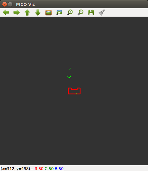
The rosbag file video of the testing is shown here PICO following the POI. A video during the actual test was not taken. | |||
[[File:Follow_POI_1.png|center|300px|link=https://youtu.be/MdFYlWa8rH8]] | |||
Latest revision as of 18:30, 17 August 2018
Student
| TU/e Number | Name | |
|---|---|---|
| 1036818 | Rokesh Gajapathy | r.gajapathy@student.tue.nl |
Introduction and Problem Definition

The motivation for "Follow Me!" project is to develop a software architecture for PICO to assist elderly person in carrying the objects and follow the person to the desired position. In this project, three levels are defined to achieve the goal in a robust manner. The elderly person is defined as a Person Of Interest (POI), static obstacles and actors are all part of the environment (World).
PICO must follow the POI, POI will not move at a speed more than 0.5 m/s (i.e) approximately 0.75 step/second. PICO should follow the POI at a distance of 0.4 m. The level one task was only designed, developed, implemented and tested. In level one, the PICO should follow the POI with the disturbances of actor in the environment. The actor cannot occlude the POI (i.e) should not come in between the POI and PICO.

The POI should pass through the middle of the target strips as shown in Figure 3, the number of target strips will be around 5. PICO should pass through 80 % of the target strip.

Initial Design
The initial design section gives an overview of the various design decisions taken to achieve the desired results. The requirements for completing the task with available resources is defined followed by the state machine and finally functional components required to achieve the state machine defined.
Available Resources
PICO is a robot with a holonomic base which can move in [math]\displaystyle{ (x,y,\theta) }[/math] directions. It consist of encoders which provides the odometery data and a Laser Range Finder (LRF) which provides an array of laser points with its ranges respectively. The output to the PICO is in terms of velocity [math]\displaystyle{ (\dot{x},\dot{y},\dot{\theta}) }[/math] through the EMC environment.
| Specification | Value | Unit |
|---|---|---|
| Detectable Distance | 0.01 to 10 | meters [m] |
| Scanning Angle | -2 to 2 | radians [rad] |
| Angular Resolution | 0.004004 | radians [rad] |
| Distance between POI and PICO | 0.4 | meters [m] |
| Speed of POI | 0.5 | meter/second [m/s] |
| Width of target strip | 1 | meter [m] |
Design Decisions
From the available resources and problem definition important design decisions are taken as follows:
1. The maximum detectable distance and scanning angle is constrained to 1.3 m and 90 degree respectively because the length of the target strip is 1 m, a equilateral triangle is drawn with respect to LRF center which is 60 degree for center, 15 degrees for left and degree right respectively.
2. The reference frame [math]\displaystyle{ (x_r,y_r) }[/math] and base frame [math]\displaystyle{ (x_b,y_b) }[/math] is defined as POI and PICO respectively. Since PICO need to follow the POI (i.e) go forward or rotate with respect to the POI.
3. The PICO moves at a speed of 0.5 m/s and rotates at 2 rad/s because the POI walks at speed of 0.5 m/s.
4. Stopping distance is 0.4 m (i.e) if the distance between POI and PICO less than 0.4 m PICO stops obtained from the problem statement
5. The delectable sensor range is split into three components left,center and right to tackle the disturbances (i.e) Actors.

Requirements
| Function | Action | Validation |
|---|---|---|
| Identify the POI (reference frame) | Two legs are identified which is close to PICO (base frame) | Visualize using lase range points, see |
| Follow the POI | Follow the POI at a distance of 0.4 m at a speed of 0.5 m/s | Walk straight in-front of the PICO |
| Rotate with respect to POI | Base frame (PICO) rotates with respect to the reference frame (POI) at 2 rad/s | Walk right and left side in-front of the PICO |
| Stop when POI stops | PICO stops when the distance between POI and PICO less than 0.4 m | Stop while walking in-front of PICO |
| Stop when POI stops | PICO stops when the distance between POI and PICO less than 0.4 m | Stop while walking in-front of PICO |
| Do not follow the Actors | Scanning Angle is constrained to 60 degree and if legs are identified in the right or left side of the PICO, it follows the one in center. | Actors walk on the side of the robot not in between the PICO and POI |
Finite State Machine

Software Architecture
The Task Software Architecture is preferred to achieve the goal of following the POI with actors in the environment because this architecture handles both continuous and discrete events. This architecture consist of the following components:
Perception (Continuous):
The perception class obtains the laser range data from the world model class and process the laser data in order to find the POI position in real-time. And also to find the actors who move around the PICO.
Monitoring (Discrete):
The monitoring class obtains the perception output from the world model and defines the present state of the robot. The monitoring states here are POI not found, POI found, Actor in left and Actor in right.
Plan (Discrete):
The plan class obtains the monitoring output states from the world model class and defines the next action to be taken by the PICO. The plan states are Stop and Follow POI
Control(Continuous):
The control actions obtains the plan state output from the world model class and provides the velocity command to each co-ordinate respectively, such as stop, move forward, rotate right and rotate left
World Model:
The world model consist of all the states and continuous variables which is obtained from perception, monitoring, plan and control functions at every iteration.
The complete cycle runs at the rate of 20 Hz (i.e) every iteration occurs at every 50 milliseconds once.
Implementation
The software architecture defined in the previous section is realized with the help of C++ programming language.
The main program consist of classes and subprograms whose functions are explained briefly as follow:
World Model:
- The world model class initialized with EMC environment Input and Output object which is laser and odometery data.
- The data types and variables for the input and output of perception(monitoring) and (plan)control programs is initialized in world model class.
- The data for each cycle is stored and retrieved from the world model.
Perception (Monitoring):
- The perception class is initialized using world model object.
- In the perception, angle of each LRF data point is found. This is implemented as a function see the LRF data to Angle
- Both perception outputs and monitoring states is implemented in the same program for simplicity.
- The monitoring states provides the position of the POI: Left, Center or Right, see the POI Position
(Plan) Control:
- The control class is initialized using world model object.
- Similar to perception (monitoring), plan states and control outputs are implemented in the same program for simplicity.
- The plan states provide the information how the PICO should move for that monitoring state, see Plan States
- Based on the plan states the control actions for PICO is provided, Control Actions
Results and Conclusion
The rosbag file video of the testing is shown here PICO following the POI. A video during the actual test was not taken.
