Embedded Motion Control 2018 Group 3: Difference between revisions
No edit summary |
|||
| (194 intermediate revisions by 6 users not shown) | |||
| Line 7: | Line 7: | ||
| 0848904 | | 0848904 | ||
| Luc (L.L.M.) van den Aker | | Luc (L.L.M.) van den Aker | ||
| l | | <tt>l dot l dot m dot v dot d dot aker at student dot tue dot nl</tt> | ||
|- | |- | ||
| 0852908 | | 0852908 | ||
| Thomas (T.) Neilen | | Thomas (T.) Neilen | ||
| t | | <tt>t dot neilen at student dot tue dot nl</tt> | ||
|- | |- | ||
| 0909434 | | 0909434 | ||
| Jeroen (J.W.) van de Valk | | Jeroen (J.W.) van de Valk | ||
| j | | <tt>j dot w dot v dot d dot valk at student dot tue dot nl</tt> | ||
|- | |- | ||
| 0896947 | | 0896947 | ||
| Nourdin (N.) Kaai | | Nourdin (N.) Kaai | ||
| n | | <tt>n dot kaai at student dot tue dot nl</tt> | ||
|- | |- | ||
| 0883056 | | 0883056 | ||
| Peter (P.) van Dooren | | Peter (P.) van Dooren | ||
| p | | <tt>p dot v dot dooren at student dot tue dot nl</tt> | ||
|- | |- | ||
| 0861750 | | 0861750 | ||
| Ties (T.J.) van Loon | | Ties (T.J.) van Loon | ||
| t | | <tt>t dot j dot v dot loon at student dot tue dot nl</tt> | ||
|- | |- | ||
|} | |} | ||
| Line 50: | Line 49: | ||
=Initial Design= | =Initial Design= | ||
The initial design is explained in the following parts: | |||
* Requirements | |||
* Functions | |||
* Components | |||
* Specifications | |||
* Interfaces | |||
Note that the report of the initial design is shared in Documents. | |||
==Requirements== | |||
* PICO should make no collisions with any walls | * PICO should make no collisions with any walls | ||
* PICO cannot stand still for 30 seconds or longer | * PICO cannot stand still for 30 seconds or longer | ||
| Line 66: | Line 70: | ||
* PICO should be able to recognize an object and stand still close to it | * PICO should be able to recognize an object and stand still close to it | ||
==Functions== | |||
* PICO should be able to drive in any direction | * PICO should be able to drive in any direction | ||
* PICO should be able to turn around | * PICO should be able to turn around | ||
| Line 75: | Line 79: | ||
* PICO should be able to recognize an object | * PICO should be able to recognize an object | ||
==Components== | |||
* Sensors: | * Sensors: | ||
** Laser Range Finder (LRF) | ** Laser Range Finder (LRF) | ||
| Line 85: | Line 89: | ||
** Ubuntu 16.04 | ** Ubuntu 16.04 | ||
==Specifications== | |||
* Translation maximum: 0.5 m/s | * Translation maximum: 0.5 m/s | ||
* Rotation maximum: 1.2 rad/s | * Rotation maximum: 1.2 rad/s | ||
| Line 92: | Line 96: | ||
* The Laser Range Finder can only measure at one height | * The Laser Range Finder can only measure at one height | ||
==Interfaces== | |||
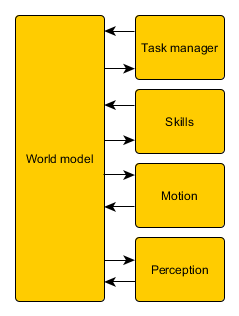
The interfaces of the initial design are shown here: | The interfaces of the initial design are shown here: | ||
[[File:InterfaceGroup3.png]] | [[File:InterfaceGroup3.png]] | ||
As shown in | As shown in the figure above, a world model is the link between all other parts. The tasks represent the highest level, meaning the most global work PICO has to do. The skills are needed to complete these tasks and some motions together form a skill. The perception contains the sensors, the continuous data. Below an overview of the different parts are given: | ||
''World model:'' | ''World model:'' | ||
| Line 125: | Line 128: | ||
* Laser Range Finder | * Laser Range Finder | ||
* Control effort | * Control effort | ||
=Escape Room Challenge= | =Escape Room Challenge= | ||
Since our code to map a room was not finished completely, a new code for the | Since our code to map a room was not finished completely, a new code for the escape room challenge was made. This code was kept simple and effective. PICO should drive to a wall, turn to the left when it detects a wall within 0.4 meters from itself, and follow the wall (without hitting it of course). Then it will scan for a hallway to exit the room. When he sees a way to exit the room, PICO will go through the opening in the wall. | ||
Our first attempt during the | Our first attempt during the escape room challange was very successful! PICO drove out of the room, but we were convinced he could do it even faster. So we set the speed higher for the second try, and it was even faster. PICO drove out of the room within 29 seconds. This resulted in a second place and being one of the two teams that made it out of the room. | ||
Here a shot video is shown of PICO leaving a room. Note that this is not filmed during the 'official' | Here a shot video is shown of PICO leaving a room. Note that this is not filmed during the 'official' escape room challenge. Due to our enthousiasm, we forgot to film, so we reconstructed the room during one of our test sessions. | ||
[[File:EscapeRoomChallenge.gif]] | [[File:EscapeRoomChallenge.gif]] | ||
=Final Design= | =Final Design= | ||
First off, the architecture is explained. | First off, the architecture is explained. This architecture is based on the theorem and takes the requirements of the hospital challenge into account. The architecture is explained in six steps: | ||
* World model | |||
* Detection | |||
* Localization | |||
* Trajectory planning | |||
* Motion control | |||
* Task manager | |||
The overall architecture is visualized here: | |||
[[File:ArchitectureCorrected.png|650px]] | |||
All six main components that are in this archtecture will be explained now. | |||
==World Model== | |||
To build a map of the hospital a twofold mapping procedure will be used. First PICO will map the room it is currently standing in. Secondly a graph connecting all mapped rooms with each other is stored. By using this two level mapping abstraction it is easier to locate PICO in a certain room. Also trajectory planning to a desired room can be more efficiently by using the graph. | |||
The data structures used to store the obtained data are the Rooms, Exits and a graph with all the Rooms. | |||
Once a room is mapped it is stored in a Room object. This object contains the width and height of the room, a global ID of the room and Exit objects. The Exit objects have a local ID, ie the ID of the exit has only meaning when the room it belongs to is also know. The exits also have a location in the coordinate frame of the room and a destination. | |||
The world model also holds the current position and the current position based on odometry. | |||
== | ===Graph=== | ||
Every room (square in figure) and door (circle in figure) will be numbered with an ID and then stored in the world model in the form of a graph. An visual representation of such graph can be seen below: | |||
[[File:Graph.png|200px]] | |||
Using the grapgh, it can be easily seen what trajectory PICO should take to find the object. As the hint states, the object will be located in the room for which most openings (i.e., doors) have to be passed through to enter it. With the use of this hint and the graph, it can be quickly determined what sequence of room ID and door IDs is the longest. Knowing this makes finding the object easier, since PICO does not have to look in every room again, bit can immeadily go to the room with the longest sequence. | |||
==Line Extraction== | |||
The first step in mapping a room is to extract line segments from the obtained laser data. For this a pre-made laser line extraction package was used. This code was slightly modified to remove the ROS layer. the source code can be found on: https://github.com/kam3k/laser_line_extraction | |||
https://github.com/kam3k/laser_line_extraction | |||
This package employs a split and merge algorithm [T. Pavlidis and S. L. Horowitz, "Segmentation of Plane Curves," in IEEE Transactions on Computers, vol. C-23, no. 8, pp. 860-870, Aug. 1974] The obtained laser data for the rooms was relatively clean, thus no filtering before the line extraction was applied. The parameters used in the algorithm needed some additional tuning to give the optimal result. | |||
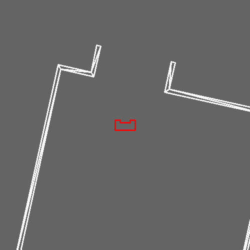
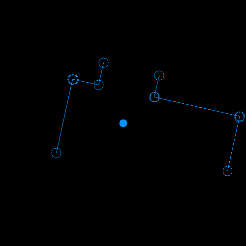
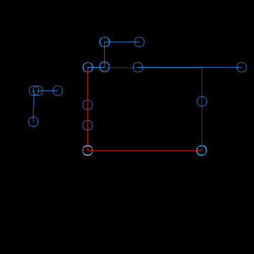
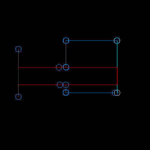
In the figures below, the lines can be seen: | |||
[[File:Line_detection_Sim.png|300px]] [[File:Line_detection_Lines.png|300px]] | [[File:Line_detection_Sim.png|300px]] [[File:Line_detection_Lines.png|300px]] | ||
==== | ==Fit Room== | ||
The | The mapping of a room is done using the lines found by the line extraction. | ||
===Saving Lines=== | |||
To map a room PICO needs to look 360° around him, however the laser range finder only has a limited range. Therefore a PICO will scan lines, turn around 180° and scan another time. It will then combine these two sets to end up with a set of lines which describe the entire room around PICO. | |||
The first time this is done pico’s position will be saved. The lines are transformed using the orientation of pico. This way the resulting lines are aligned with the global axis system but the 0,0 position is at pico’s location. This new frame will be called the mappedFrame. | |||
after rotating 180 degrees. Pico will merge the detected lines. First the lines are transformed to the mapping frame. Then the lines are compared to the lines already saved. If the lines are collinear, (they have similar same radius and angle) the lines are checked for overlap. The start and end points of the new line are projected on the compared line. If either of the projected point lies on the old line with some margin of error. The line is merged. This is done by taking the furthest start and end point. | |||
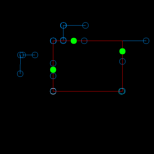
In the figures below, the two sets of lines can be seen, followed by the merged set of lines: | |||
[[File:Transform_sim.png|300px]] [[File:Transform_lines.png|300px]] [[File:Merged_lines.png|300px]] | |||
===Determine dimensions=== | |||
Once PICO has assembled a set of lines all around him, he can determine the properties of the room he is in. This is done in two steps: | |||
* The dimensions of the room are found. | |||
* All the exits of the room are found. | |||
A box is defined with a distances to the left, to the right, above and below pico. The width and height of the room are determined by fitting the largest possible box inside the lines in mergedLines. An initial guess for the distances is made using the minimum radii of all lines which have the right orientation. Each line in mergedLines can be determined to be either to the left, to the right, above and below pico. | |||
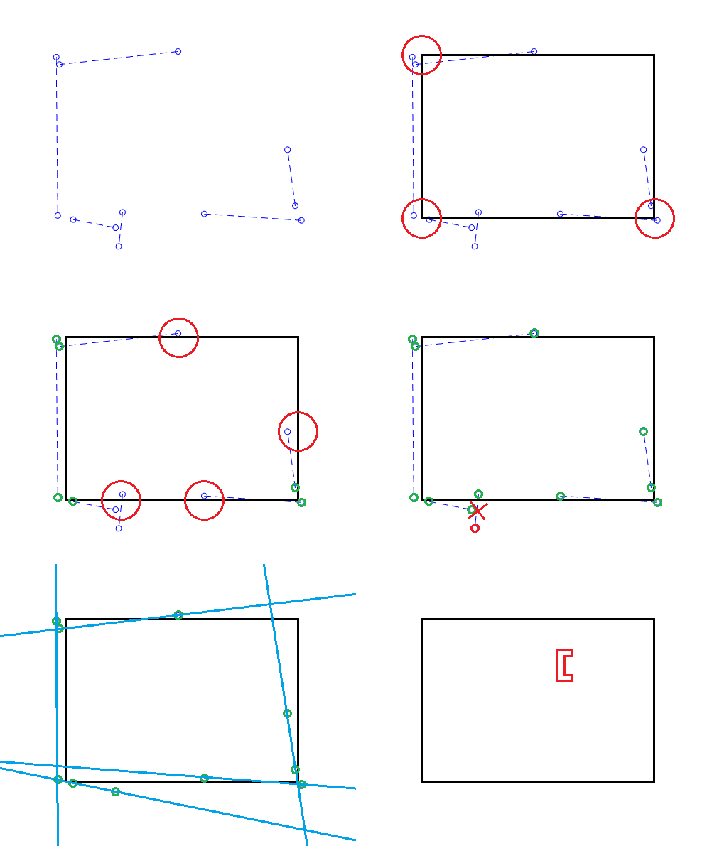
For example, consider the left wall of the room. In the figure below three lines have the correct orientation to belong to that wall. The initial estimate for the distance to the left of pico is chosen as the smallest radius among those three lines. The same is done for the other three walls. | |||
After the initial estimate it is possible that the box is still smaller than the room. This can be caused by lines outside the room which happen to have a smaller radius. To expand the size of the room an iterative procedure is used. One side at a time the function checks whether the room can be expanded in this direction. It again searches for a minimum radius among a selection of lines, however this time a criteria is added that the line must fall within the estimated box after expansion. This will filter out most lines outside of the room. The procedure continues until it has gone one cycle without updating the distances. Using the distances left, right, up and down the width and height of the room can be determined as well as the location of pico in this new room, expressed in the new room frame. | |||
[[File:testRoomMergedLines.png|200px]] | |||
[[File:testRoomFit1.png|200px]] | |||
[[File:testRoomFit2.png|200px]] | |||
[[File:testRoomFit3.png|200px]] | |||
There are edge cases where this procedure goes wrong however they are considered rare enough that they are not taken into account. | |||
[[File:EdgeCaseRoomFit.png|300px]] | |||
===Find exits=== | |||
In order to find the exits a function is made which once again loops over the lines in mergedLines. It will determine whether a line belongs to the room as determined by the dimensions previously established. If the gap between two consecutive lines which belong to the room is the size of a door (between 0.4 and 1.7m). An exit is added there. After looping over all lines a final check is done to determine whether an exit exists between the first and last lines in mergedLines. | |||
[[File:testRoomExits.png|300px]] | |||
===Adding the room to the world model=== | |||
After the room has been fitted it must be added to the map in the world model. There are several properties of the room which still need to be determined. | |||
The location of the room coordinate frame is calculated using the room coordinate frame of the previous room, the location of pico in the previous room frame (mappedFrame) and the location of pico in the new room. | |||
The exit pico went through in the previous room must be linked to an exit found in the new room. This is done by calculating the distance from the exits in the new room to the exit taken in the previous room. The exit with the smallest distance is linked to this new room. The destinations of the two exits are set and the exit in the new room is moved to the front of the vector with exits so that exits[0] always leads back to the hallway. | |||
Finally pico's location and current room are updated to be in the new room. | |||
==Localization== | |||
Once a room has been mapped. PICO will be able to compare the detected lines to the map it has made. Based on this, PICO's location can be determined. As the odometry data of PICO is unreliable, another solution had to be made to reliably navigate through the environment. A solution had to be made that navigates PICO based on the local coordinates of a room. To do this three different functionalities had to be implemented: | |||
* Make an initial guess of PICO’s position within a room. | |||
* Determine which lines are part of a specific room. | |||
* Determine PICO’s position based on LRF-data. | |||
[[File:Localisation_animation.gif]] | |||
===Initial guess=== | |||
The localisation script constantly provides information on PICO’s position. When PICO is leaving a room through a door to another room, this position is used as an initial guess for PICO’s current coordinates. Using these coordinates the lines that PICO sees can be transformed to the coordinate frame of the new room. | |||
===Line filtering=== | |||
The lines that PICO sees are converted to the coordinate system of the room. Based on the information previously gathered about a specific room it is determined which of the lines that PICO currently sees are actually part of the room itself. This is to prevent that for example lines from a hallway are used in the localisation. First it is checked if the end points of the lines directly coincide with the corners of the room. A vector is spanned between the coordinates of a corner and the end point under consideration. The norm of this vector should not exceed a certain parameter in order to be considered to be part of the room. Another possibility is that the end point of a line lies on the contour of a room. In order to determine if this is happening the closest distance of this end point to the line spanned by the two nearby corners should be determined. This can be done using simple vector calculus. | |||
The shortest distance between a line the origin is expressed in the following equation: | |||
<math>\left(\begin{pmatrix}x_{p_{1}}\\y_{p_{1}}\\\alpha_{p_{1}}\end{pmatrix}+t\begin{pmatrix}x_{p_{1}}-x_{p_{2}}\\y_{p_{1}}-y_{p_{2}}\\\alpha_{p_{1}}-\alpha_{p_{2}}\end{pmatrix}\right)\cdot\begin{pmatrix}x_{p_{1}}-x_{p_{2}}\\y_{p_{1}}-y_{p_{2}}\\\alpha_{p_{1}}-\alpha_{p_{2}}\end{pmatrix}=0</math> | |||
In this equation <math>p_{1}</math> and <math>p_{2}</math> are calculated by substracting the end point of the line under consideration from the corners of the room. <math>t</math> is calculated, and substituted in the following equation to obtain the vector spanned between the end point and the line: | |||
<math>\begin{pmatrix}x_{p_{1}}\\y_{p_{1}}\\\alpha_{p_{1}}\end{pmatrix}+t\begin{pmatrix}x_{p_{1}}-x_{p_{2}}\\y_{p_{1}}-y_{p_{2}}\\\alpha_{p_{1}}-\alpha_{p_{2}}\end{pmatrix}</math> | |||
The length of this vector is also compared with the fixed parameter used to test the coincidence of the end points and the corners. | |||
===Localisation=== | |||
Because the lines are created in a certain way, it can be derived to which of the four walls they belong. The start- and end points of lines are defined in a counter-clockwise manner around the coordinate system, and the angle of the lines is calculated with respect to the x-axis of a this coordinate system. The lines corresponding to the rightmost wall would thus have an angle corresponding to <math>0</math> radians, the upper walls <math>\frac{1}{2}\pi</math> radians, the leftmost walls <math>\pi</math> radians and the lower walls <math>\frac{3}{2}\pi</math> radians. When it is determined which lines belong to which walls, information about the distance from PICO to these walls is extracted from the untransformed lines. This information is used to calculate PICO’s x and y coordinates in a room, by comparing the data to the previously stored width and height of a room. | |||
===Angle Estimation=== | |||
The odometry on PICO gives an estimate of the orientation of PICO. However due to the nature of odometry this estimate will drift over time. Therefore an absolute measurement of the angle is necessary to reset the odometry measurement. This is done using the lines extracted by PICO. These lines have a radius and an angle relative to PICO. Since the hospital is contructed of perpendicular lines PICO can determine it's angle relative to the walls. By using an initial guess, which will give the general direction PICO is oriented in, i.e. whether its angle is around <math>0</math>, <math>\dfrac{1}{2}\pi</math>, <math>\pi</math>, or <math>-\frac{1}{2}\pi</math>. Then the angle is corrected y using the following equation on the measurement: | |||
<math>estimate +mod_{0.5 * \pi}(measuredAngle)</math> | |||
==Trajectory Planning== | |||
This part plans the trajectory PICO should take during the hospital challenge. | |||
===Approaching a Door=== | |||
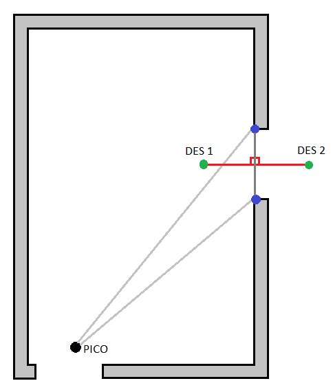
From the worldmodel PICO obtains his current position, and the position of the two corners of the door. A function is made which basically calculates a point right in the middle of the two corners, and puts a setpoint at a specified distance in front of the midpoint of the door and behind the midpoint of the door seen in the Figure below. Using the P-controller and the repulsion, this setpoint can be reached by PICO. PICO first changes the angle and drives forwards to the 'DES 1' setpoint, when this setpoint is reached the angle changes again and starts driving to the second 'DES 2' setpoint. | |||
[[File:Draw1x.png|300px]] | |||
==== | ==Motion Control== | ||
This part explains the methods used to perform the motion as dictated from the trajectory planning. | |||
=== | ===Repulsion=== | ||
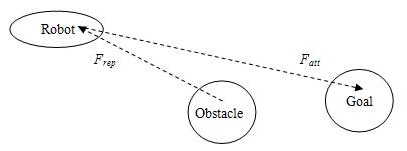
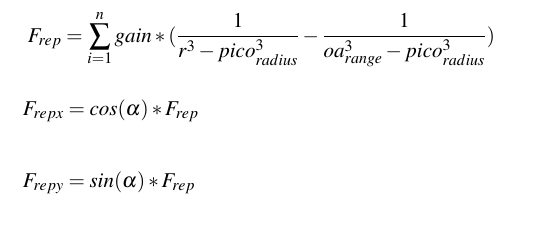
A function is implemented which keeps PICO from touching the walls. This is done using a repulsion forces. The repulsion force is calculated using the reciprocal of the laser scan data. The laser data is scanned over the entire range of the sensor, except for the first 10 points and the last 10 points because the returned laser data at these points was not trustworthy (some laser data points where found inside the radius of PICO itself). For each sensor reading a repulsion force is calculated in the x and y direction, the Equation used for this calculation can be seen below. As can be seen PICO's radius is taken into account, this way the force goes to infinity when PICO is almost touching a wall or object. The force at the border of the obstacle avoidance range (oa_range) is zero to make sure the force gradually increases, a power to the third order is used to make sure the increase in force is exponential. By adding up all the repulsion forces over the entire scan range a single force vector is obtained. By putting this 'force' combined with a gain directly into PICO's speed input, it will have the tendency to drive away from walls. A tuning parameter has been made in the form of a maximum distance of 0.35m in which PICO can approach a wall (oa_range). All laser data points which are larger than this value are ignored. Since the laser data only covers 240° of view PICO always changes its angle to drive with its head forward to the destination coordinates. This way there is always available laser data to avoid obstacles. | |||
[[File:draw2x.jpg]] | |||
[[File:draw4.png]] | |||
=== | ===P-controller=== | ||
A | In order to have PICO move from point A to point B a simple P-controller has been implemented. For testing purposes the P-controller currently relies on odometry data. The 'error' is calculated by subtracting the current position from the target position. The error is multiplied with a proportional action. During testing these parameters will be tuned to ensure optimal behavior of PICO. | ||
=== | ===P-controller with Repulsion=== | ||
The speed outputted by the P-controller and the speed generated by the repulsion function are simultaneously used in the PICO speed command. This means that, for example, when PICO is closing in on a corner, the speed (depending on the direction in which PICO is oriented) is temporarily reduced in the direction of the walls, ensuring that PICO gets enough clearance before returning on his path. A problem arises however when a setpoint is located directly behind a wall. In this case PICO cannot reach his goal, as the P-controller 'pulls' PICO towards the setpoint, while the repulsion 'pushes' PICO away from the walls. Therefore it is necessary to give PICO setpoints which he can roughly 'see'. The generation of these setpoints is handled in one of the previous sections. To make sure the maximum translation velocity in the x and y direction is not exceeded the norm of both speeds are calculated, when the velocity exceeds the maximum translation speed it is lowered. | |||
== | ==Task Manager== | ||
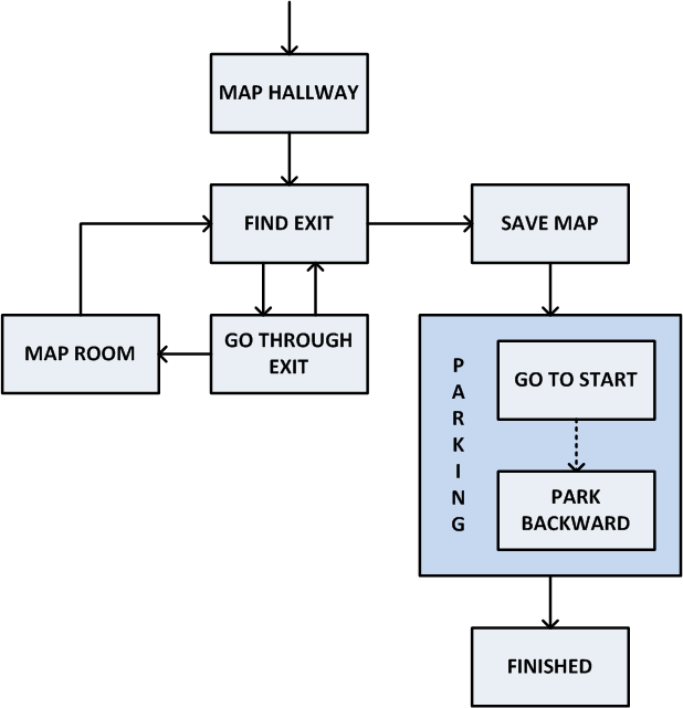
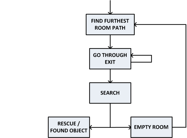
The | The task manager states what task should take place at what moment. The task manager contains three tasks: | ||
* Exploration | |||
* Parking | |||
* Search and rescue | |||
The charts of these tasks are shown below. The left one shows exploration and parking, and the right one shows search and rescue: | |||
=== | [[File:MappingX.png|350px]] [[File:SearchRescueX.png|400px]] | ||
These three tasks will be highlighted in more detail now. | |||
===Exploration=== | |||
Starting the hospital challenge, exploration is the first task to complete. Starting in the corridor, the detection of this area will be done. This corridor is saved in a struct, which contains a vector of exits. These exits have a destination. In the beginning, each of these destinations have value -1. The exploration is programmed in such a way that always the exit with a destination of -1 will be taken, so always an unexplored room will be entered. After entering a new room, again detection will scan the area. The destination of the door through which PICO has entered the room, will change from -1 to a value belonging to the previous area (corridor in this case). Then, if a room is entered and more than one exit is detected, again the door with unknown destination will be chosen. In the end, all unknown exits are explored and PICO is back in the corridor. At this moment PICO should move to its starting position and parking phase will begin. | |||
===Parking=== | |||
When the map building is complete, PICO has to park backwards to the wall behind the starting position. Parking is done upon touching the wall. After PICO parked, PICO should say: "I am parked!". | When the map building is complete, PICO has to park backwards to the wall behind the starting position. Parking is done upon touching the wall. After PICO parked, PICO should say: "I am parked!". | ||
| Line 201: | Line 297: | ||
[[File:BackwardParking.gif]] | [[File:BackwardParking.gif]] | ||
Note that this is a GIF, so you can't hear PICO say "I am parked!". | Note that this is a GIF, so you can't hear PICO say "I am parked!". | ||
After parking, the last phase of the challenge can begin. This phase will be explained in Search and Rescue. | |||
===Search and Rescue=== | |||
At this moment, the hospital is explored and mapped. In the world model, a graph is saved. As discussed before, the hint states that the object will be located in the room for which most openings (i.e., doors) have to be passed through to enter it. With the use of this hint and the graph, the position of the object should be known and PICO can drive towards it. Standing still in front of this object will be the end of the challenge. In case there are multiple rooms for which the most doors have to be passed through, PICO should just try one and in case the object is not found, the other possibility should be tried. | |||
For now, the code calculates the longest path and stores this value. Because of the graph, PICO always knows which exit to take. After taking all these exits, the room with the object is entered. As explained, there can be multiple options. However, this is not fixed yet and will be one of the recommendations. After entering the room with the object, the object search function will be called. In this function, the LRF data is used. For each laserpoint, the differences between its distance and the distance of laserpoints on the left and on the right are measured. If that difference is high enough, there has to be an object in the room. This function places a point in front of the object and PICO will drive towards that point with the normal motion functions and will speak 'I found the object'. This search and rescue is shown in the GIF below. | |||
=Hospital Challenge= | |||
On June 13th, the hospital challenge took place. It is expected to fail on localization. Besides that, most of the code works the way it should, independent of the way the hospital is build. | |||
==Evaluation== | |||
Since localization did not work yet, PICO was localized with the help of its odometry. As known, this odometry is not accurate. After a few meters, the errors are increasing and after a while the position where PICO thinks to be and its actual position differed lot. This was the reason the challenge was not successful. PICO started mapping the corridor. It located two exits and moved through one of these, as it is expected to do. Mapping the first room again worked as it should. Two exits were found and PICO knew it should take the door to an unknown place. Moving through that door worked just fine. Mapping that room worked, but then PICO should move to the door through where it entered. However, this door was not at the right position anymore. Or better, PICOs location was too different from where it thought it was. This meant there was a wall on a place of an exit, meaning PICO wanted to go through that wall. The force field made sure PICO did not bump into the wall, but the door was not found. This was the end of the challenge. Both trials did not succeed because of this reason. This was not the only disadvantage of our code. Mapping the corridor did not work perfectly, because of its dimensions. Since the width of the corridor was a lot smaller than its height, mapping the corridor was hard. There was not enough laserdata to have a good visualization of the end of the corridor. That is why only two exits were mapped instead of three. To correct this, PICO should move further into the corridor and map again. | |||
==Simulator== | |||
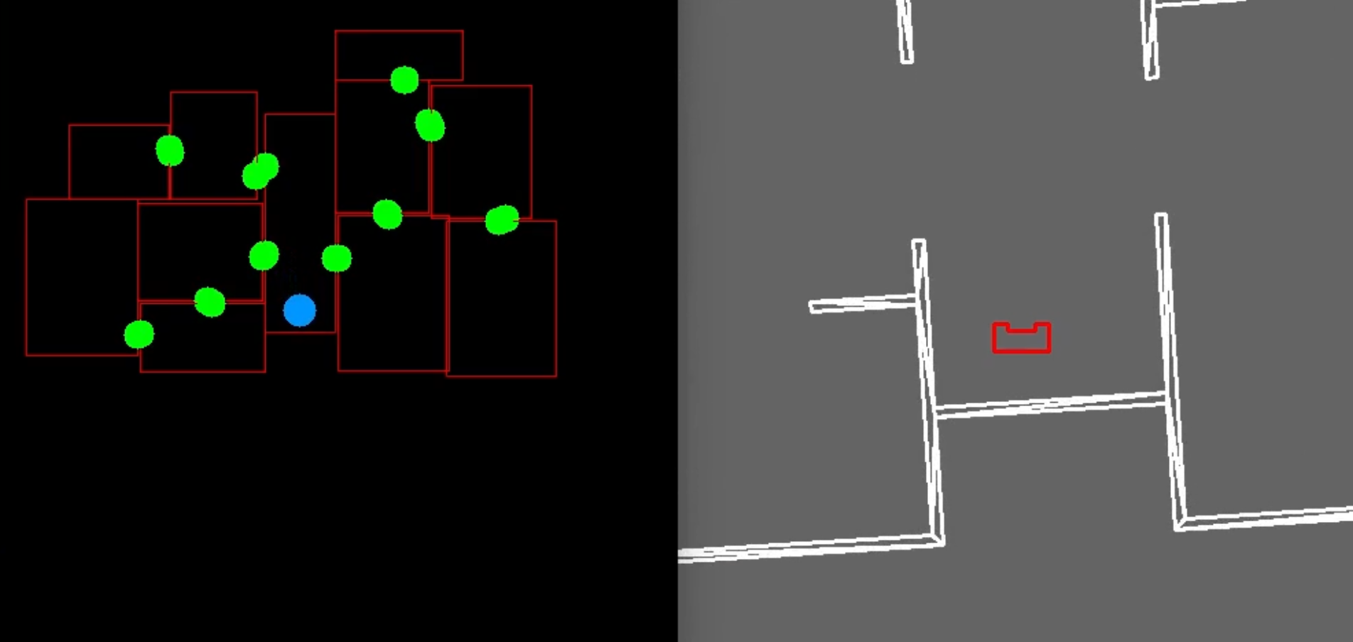
The main reason why the hospital challenge did not succeed was because of localization. This is not a problem in simulation. Localizing on odometry works just fine in simulation. Both the mapping and parking phase are shown in the YouTube video. As can be seen, mapping in the corridor starts in the middle of the corridor: | |||
''Click on the image to go to the YouTube video.'' | |||
[[File:ThumbnailHospital.png|300px|link=https://youtu.be/xx87YWtambs]] | |||
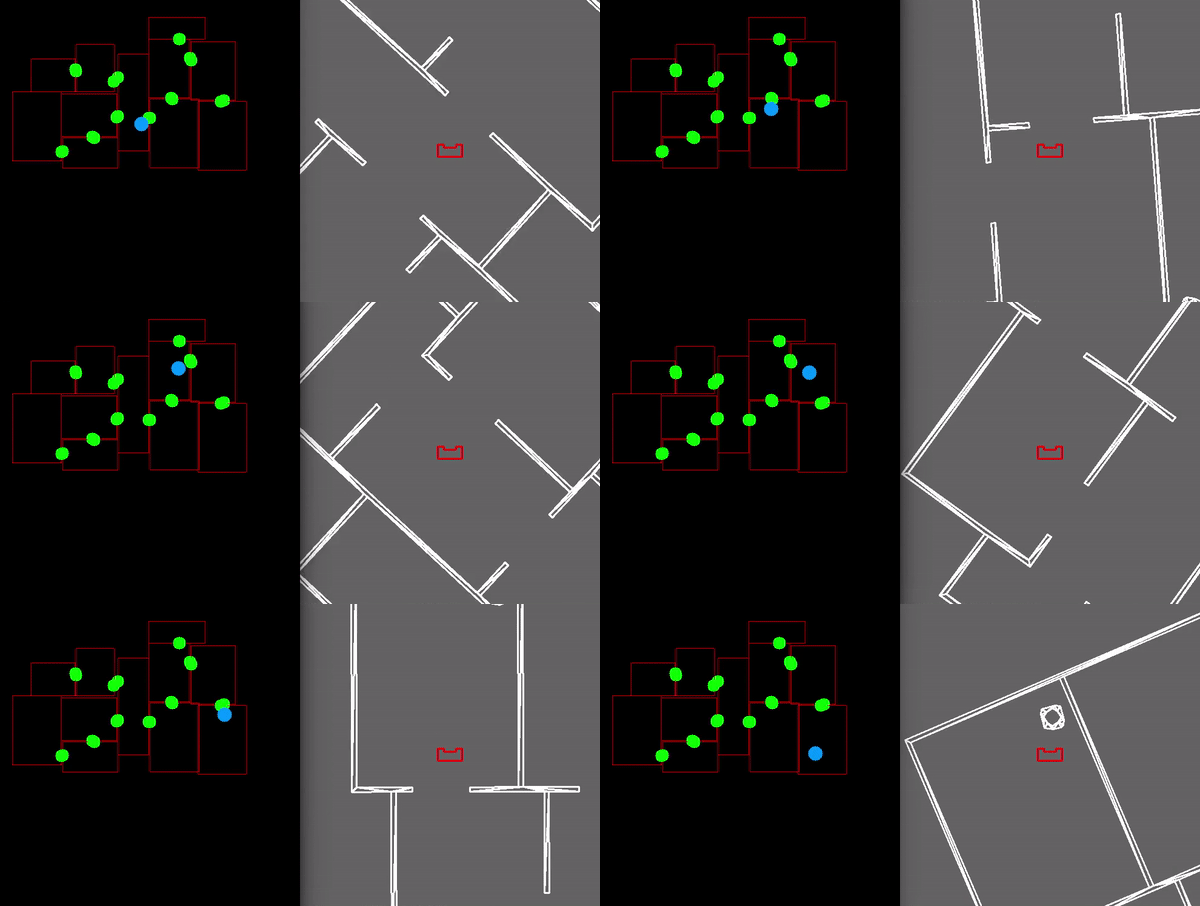
The search and rescue phase is shown in the following GIF: | |||
[[File:HospitalSearch.gif]] | |||
==The Real Challenge== | |||
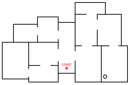
As seen above, PICO thinks the hospital challenge is not an actual challenge for him... To see what PICO can do, a real challenge was created. This is done with the following map, which is far more challenging due to its size, number of rooms, and especially more diversity of door sizes and positions. | |||
[[File:TheRealChallenge.png|350px]] | |||
Without wasting any more words, both the mapping and parking phase are shown in the YouTube video: | |||
''Click on the image to go to the YouTube video.'' | |||
[[File:ThumbnailReal.png|300px|link=https://youtu.be/pVJy6qWZcw8]] | |||
The search and rescue phase is shown in the following GIF: | |||
[[File:RealSearch.gif]] | |||
=Documents= | |||
All the documents made, besides the Wiki page itself, are shared here. | |||
==Report of Initial Design== | |||
Due to a misunderstanding, the report was not uploaded as a PDF yet. However, the full report was uploaded on this Wiki page (see below) before May 11th (17.00h), and now it is also uploaded as a PDF file (<1Mb). Our apologies for any inconvenience. The PDF of the report of the initial design can be found here: [[File:InitialDesign_Group3_Report.pdf]] | |||
==Presentation of Initial Design== | |||
On May 16th, all groups presented their initial design. So we presented our initial design too and included two GIFs of our process so far. A PDF of the slides can be found here: [[File:InitialDesign_Group3_Presentation.pdf]] | |||
==Presentation of Final Design== | ==Presentation of Final Design== | ||
On June 6th, the final presentation was presented to the other groups. This presentation of the final design mainly focussed on the architecture. A PDF of the slides can be found here: [[File:FinalDesign_Group3_Presentation.pdf]] | |||
= | =Code= | ||
Below several pieces of code can be found of which our group is particularly proud. These include the structures that form our map as well as the room fitting procedure. Our obstacle avoidance function is also included since this allows us to drive collision free even if the map is not 100% accurate. | |||
Structures used in the map | |||
[https://gitlab.tue.nl/EMC2018/group3/snippets/30 worldModel_structures] | |||
Room fit procedure | |||
[https://gitlab.tue.nl/EMC2018/group3/snippets/31 Room_fitting] | |||
Obstacle avoidance | |||
[https://gitlab.tue.nl/EMC2018/group3/snippets/32 Obstacle_avoidance] | |||
Latest revision as of 13:46, 25 June 2018
Group Members
| TU/e Number | Name | |
|---|---|---|
| 0848904 | Luc (L.L.M.) van den Aker | l dot l dot m dot v dot d dot aker at student dot tue dot nl |
| 0852908 | Thomas (T.) Neilen | t dot neilen at student dot tue dot nl |
| 0909434 | Jeroen (J.W.) van de Valk | j dot w dot v dot d dot valk at student dot tue dot nl |
| 0896947 | Nourdin (N.) Kaai | n dot kaai at student dot tue dot nl |
| 0883056 | Peter (P.) van Dooren | p dot v dot dooren at student dot tue dot nl |
| 0861750 | Ties (T.J.) van Loon | t dot j dot v dot loon at student dot tue dot nl |
Initial Design
The initial design is explained in the following parts:
- Requirements
- Functions
- Components
- Specifications
- Interfaces
Note that the report of the initial design is shared in Documents.
Requirements
- PICO should make no collisions with any walls
- PICO cannot stand still for 30 seconds or longer
- For the escape room challenge, the robot should leave the room within 5 minutes
- For the hospital challenge, within 5 minutes, mapping, reverse parking and obtaining the object should be done
- Its surroundings should be made visible in a map
- PICO should be able to reach every position in the room
- PICO should be able to leave every room
- PICO should make distinction between the hall and rooms
- It should run autonomously, so in each challenge there should be no additional input
- To start your software, only one executable has to be called
- PICO should be able to recognize an object and stand still close to it
Functions
- PICO should be able to drive in any direction
- PICO should be able to turn around
- It should be able to detect walls
- PICO has to know its own position within the mapped map
- PICO is able to construct a map
- It should be possible to create a trajectory to a room
- PICO should be able to recognize an object
Components
- Sensors:
- Laser Range Finder (LRF)
- Wheel encoders (odometry)
- Actuator:
- Holonomic base (omni-wheels)
- Computer:
- Intel i7
- Ubuntu 16.04
Specifications
- Translation maximum: 0.5 m/s
- Rotation maximum: 1.2 rad/s
- Range of Laser Range Finder is assumed to be bigger than maximum room dimension
- The field of view of the Laser Range Finder is from -2 rad to 2 rad, divided in pieces of 0.004004
- The Laser Range Finder can only measure at one height
Interfaces
The interfaces of the initial design are shown here:
As shown in the figure above, a world model is the link between all other parts. The tasks represent the highest level, meaning the most global work PICO has to do. The skills are needed to complete these tasks and some motions together form a skill. The perception contains the sensors, the continuous data. Below an overview of the different parts are given:
World model:
- Compose map
- Object recognition
Tasks:
- Mapping of the environment
- Backward parking at the specified location
- Searching for the object
Skills:
- Planning a trajectory
- Collision avoidance
- Backward parking
- Navigate
- Positioning in front of an opening
- Compose maps
Motion:
- Translation
- Rotation
Perception:
- Odometry
- Laser Range Finder
- Control effort
Escape Room Challenge
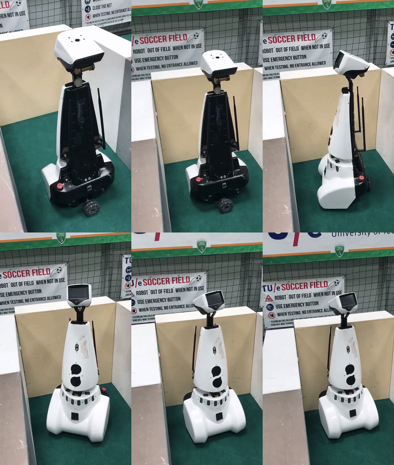
Since our code to map a room was not finished completely, a new code for the escape room challenge was made. This code was kept simple and effective. PICO should drive to a wall, turn to the left when it detects a wall within 0.4 meters from itself, and follow the wall (without hitting it of course). Then it will scan for a hallway to exit the room. When he sees a way to exit the room, PICO will go through the opening in the wall.
Our first attempt during the escape room challange was very successful! PICO drove out of the room, but we were convinced he could do it even faster. So we set the speed higher for the second try, and it was even faster. PICO drove out of the room within 29 seconds. This resulted in a second place and being one of the two teams that made it out of the room.
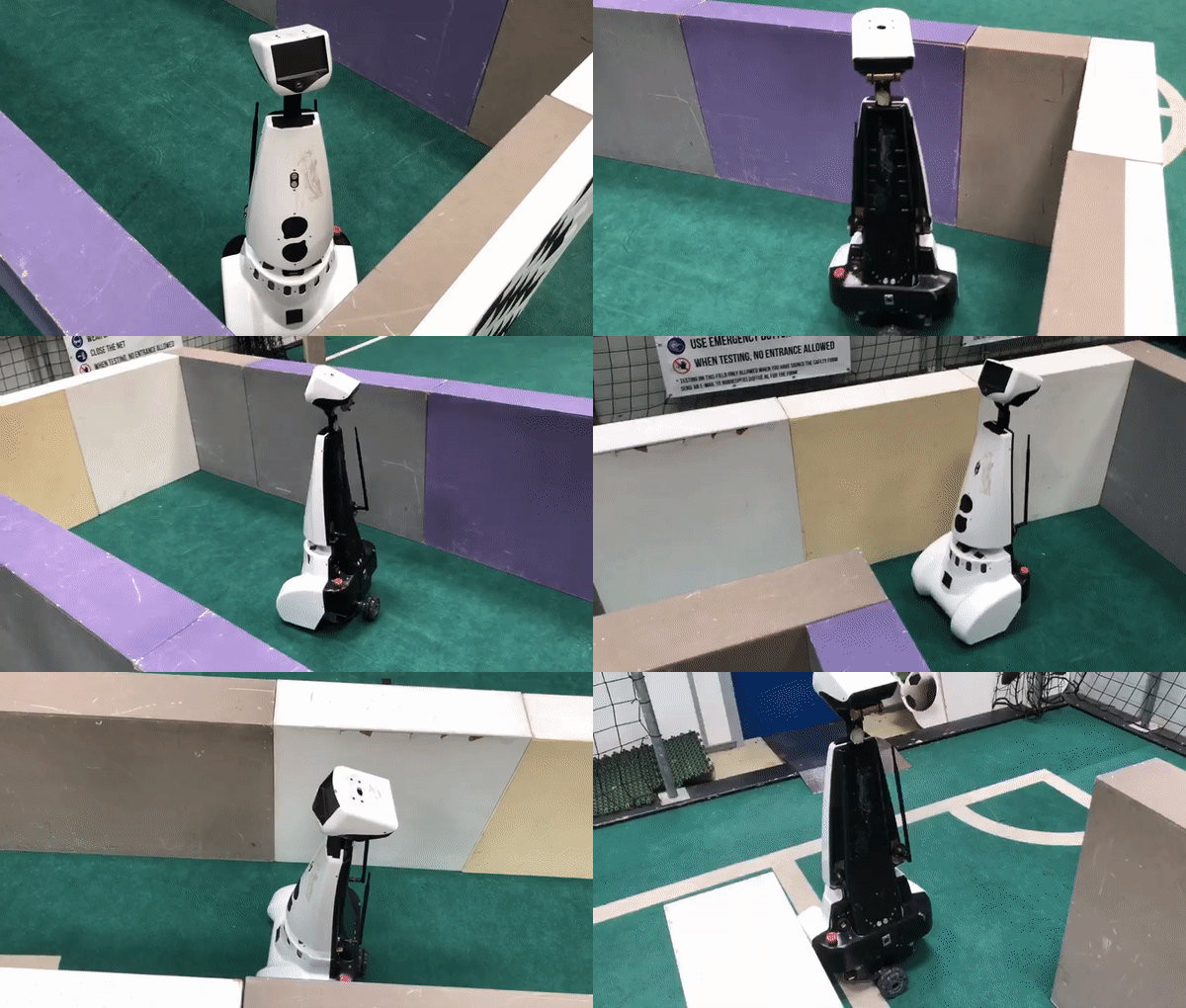
Here a shot video is shown of PICO leaving a room. Note that this is not filmed during the 'official' escape room challenge. Due to our enthousiasm, we forgot to film, so we reconstructed the room during one of our test sessions.
Final Design
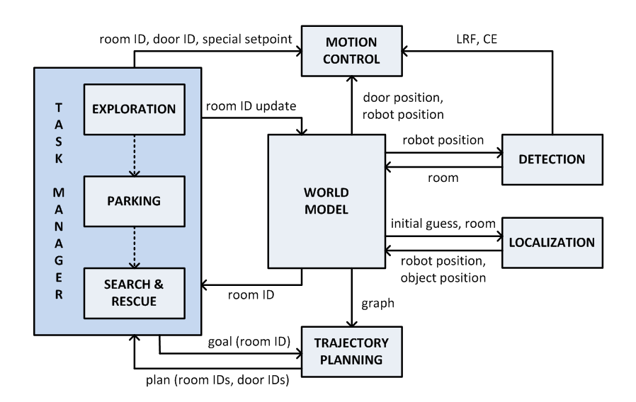
First off, the architecture is explained. This architecture is based on the theorem and takes the requirements of the hospital challenge into account. The architecture is explained in six steps:
- World model
- Detection
- Localization
- Trajectory planning
- Motion control
- Task manager
The overall architecture is visualized here:
All six main components that are in this archtecture will be explained now.
World Model
To build a map of the hospital a twofold mapping procedure will be used. First PICO will map the room it is currently standing in. Secondly a graph connecting all mapped rooms with each other is stored. By using this two level mapping abstraction it is easier to locate PICO in a certain room. Also trajectory planning to a desired room can be more efficiently by using the graph. The data structures used to store the obtained data are the Rooms, Exits and a graph with all the Rooms. Once a room is mapped it is stored in a Room object. This object contains the width and height of the room, a global ID of the room and Exit objects. The Exit objects have a local ID, ie the ID of the exit has only meaning when the room it belongs to is also know. The exits also have a location in the coordinate frame of the room and a destination. The world model also holds the current position and the current position based on odometry.
Graph
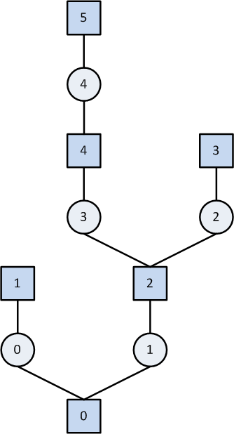
Every room (square in figure) and door (circle in figure) will be numbered with an ID and then stored in the world model in the form of a graph. An visual representation of such graph can be seen below:
Using the grapgh, it can be easily seen what trajectory PICO should take to find the object. As the hint states, the object will be located in the room for which most openings (i.e., doors) have to be passed through to enter it. With the use of this hint and the graph, it can be quickly determined what sequence of room ID and door IDs is the longest. Knowing this makes finding the object easier, since PICO does not have to look in every room again, bit can immeadily go to the room with the longest sequence.
Line Extraction
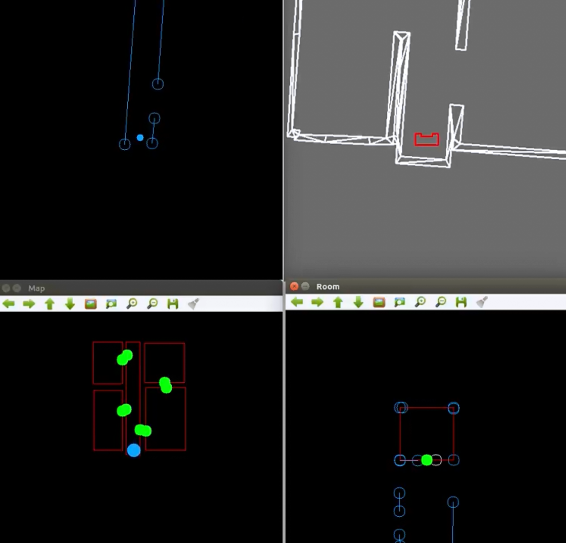
The first step in mapping a room is to extract line segments from the obtained laser data. For this a pre-made laser line extraction package was used. This code was slightly modified to remove the ROS layer. the source code can be found on: https://github.com/kam3k/laser_line_extraction
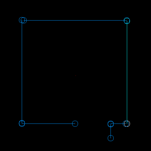
This package employs a split and merge algorithm [T. Pavlidis and S. L. Horowitz, "Segmentation of Plane Curves," in IEEE Transactions on Computers, vol. C-23, no. 8, pp. 860-870, Aug. 1974] The obtained laser data for the rooms was relatively clean, thus no filtering before the line extraction was applied. The parameters used in the algorithm needed some additional tuning to give the optimal result. In the figures below, the lines can be seen:
Fit Room
The mapping of a room is done using the lines found by the line extraction.
Saving Lines
To map a room PICO needs to look 360° around him, however the laser range finder only has a limited range. Therefore a PICO will scan lines, turn around 180° and scan another time. It will then combine these two sets to end up with a set of lines which describe the entire room around PICO.
The first time this is done pico’s position will be saved. The lines are transformed using the orientation of pico. This way the resulting lines are aligned with the global axis system but the 0,0 position is at pico’s location. This new frame will be called the mappedFrame.
after rotating 180 degrees. Pico will merge the detected lines. First the lines are transformed to the mapping frame. Then the lines are compared to the lines already saved. If the lines are collinear, (they have similar same radius and angle) the lines are checked for overlap. The start and end points of the new line are projected on the compared line. If either of the projected point lies on the old line with some margin of error. The line is merged. This is done by taking the furthest start and end point.
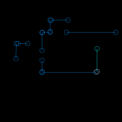
In the figures below, the two sets of lines can be seen, followed by the merged set of lines:
Determine dimensions
Once PICO has assembled a set of lines all around him, he can determine the properties of the room he is in. This is done in two steps:
- The dimensions of the room are found.
- All the exits of the room are found.
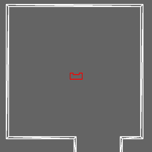
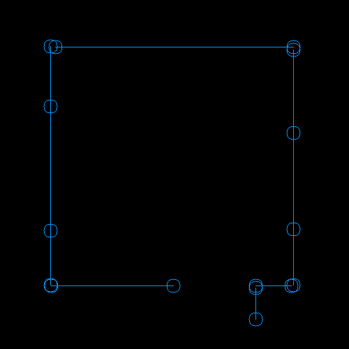
A box is defined with a distances to the left, to the right, above and below pico. The width and height of the room are determined by fitting the largest possible box inside the lines in mergedLines. An initial guess for the distances is made using the minimum radii of all lines which have the right orientation. Each line in mergedLines can be determined to be either to the left, to the right, above and below pico.
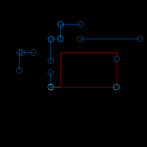
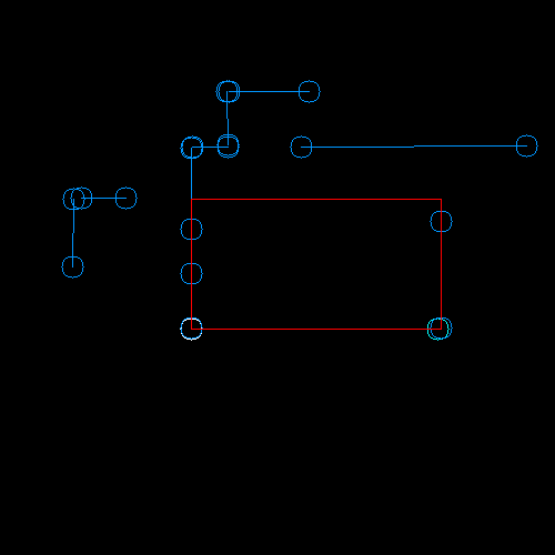
For example, consider the left wall of the room. In the figure below three lines have the correct orientation to belong to that wall. The initial estimate for the distance to the left of pico is chosen as the smallest radius among those three lines. The same is done for the other three walls.
After the initial estimate it is possible that the box is still smaller than the room. This can be caused by lines outside the room which happen to have a smaller radius. To expand the size of the room an iterative procedure is used. One side at a time the function checks whether the room can be expanded in this direction. It again searches for a minimum radius among a selection of lines, however this time a criteria is added that the line must fall within the estimated box after expansion. This will filter out most lines outside of the room. The procedure continues until it has gone one cycle without updating the distances. Using the distances left, right, up and down the width and height of the room can be determined as well as the location of pico in this new room, expressed in the new room frame.
There are edge cases where this procedure goes wrong however they are considered rare enough that they are not taken into account.
Find exits
In order to find the exits a function is made which once again loops over the lines in mergedLines. It will determine whether a line belongs to the room as determined by the dimensions previously established. If the gap between two consecutive lines which belong to the room is the size of a door (between 0.4 and 1.7m). An exit is added there. After looping over all lines a final check is done to determine whether an exit exists between the first and last lines in mergedLines.
Adding the room to the world model
After the room has been fitted it must be added to the map in the world model. There are several properties of the room which still need to be determined. The location of the room coordinate frame is calculated using the room coordinate frame of the previous room, the location of pico in the previous room frame (mappedFrame) and the location of pico in the new room. The exit pico went through in the previous room must be linked to an exit found in the new room. This is done by calculating the distance from the exits in the new room to the exit taken in the previous room. The exit with the smallest distance is linked to this new room. The destinations of the two exits are set and the exit in the new room is moved to the front of the vector with exits so that exits[0] always leads back to the hallway. Finally pico's location and current room are updated to be in the new room.
Localization
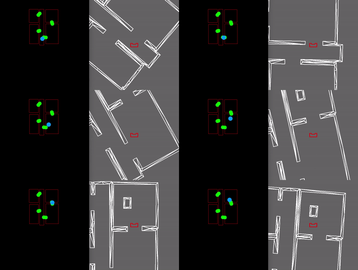
Once a room has been mapped. PICO will be able to compare the detected lines to the map it has made. Based on this, PICO's location can be determined. As the odometry data of PICO is unreliable, another solution had to be made to reliably navigate through the environment. A solution had to be made that navigates PICO based on the local coordinates of a room. To do this three different functionalities had to be implemented:
- Make an initial guess of PICO’s position within a room.
- Determine which lines are part of a specific room.
- Determine PICO’s position based on LRF-data.
Initial guess
The localisation script constantly provides information on PICO’s position. When PICO is leaving a room through a door to another room, this position is used as an initial guess for PICO’s current coordinates. Using these coordinates the lines that PICO sees can be transformed to the coordinate frame of the new room.
Line filtering
The lines that PICO sees are converted to the coordinate system of the room. Based on the information previously gathered about a specific room it is determined which of the lines that PICO currently sees are actually part of the room itself. This is to prevent that for example lines from a hallway are used in the localisation. First it is checked if the end points of the lines directly coincide with the corners of the room. A vector is spanned between the coordinates of a corner and the end point under consideration. The norm of this vector should not exceed a certain parameter in order to be considered to be part of the room. Another possibility is that the end point of a line lies on the contour of a room. In order to determine if this is happening the closest distance of this end point to the line spanned by the two nearby corners should be determined. This can be done using simple vector calculus.
The shortest distance between a line the origin is expressed in the following equation:
[math]\displaystyle{ \left(\begin{pmatrix}x_{p_{1}}\\y_{p_{1}}\\\alpha_{p_{1}}\end{pmatrix}+t\begin{pmatrix}x_{p_{1}}-x_{p_{2}}\\y_{p_{1}}-y_{p_{2}}\\\alpha_{p_{1}}-\alpha_{p_{2}}\end{pmatrix}\right)\cdot\begin{pmatrix}x_{p_{1}}-x_{p_{2}}\\y_{p_{1}}-y_{p_{2}}\\\alpha_{p_{1}}-\alpha_{p_{2}}\end{pmatrix}=0 }[/math]
In this equation [math]\displaystyle{ p_{1} }[/math] and [math]\displaystyle{ p_{2} }[/math] are calculated by substracting the end point of the line under consideration from the corners of the room. [math]\displaystyle{ t }[/math] is calculated, and substituted in the following equation to obtain the vector spanned between the end point and the line:
[math]\displaystyle{ \begin{pmatrix}x_{p_{1}}\\y_{p_{1}}\\\alpha_{p_{1}}\end{pmatrix}+t\begin{pmatrix}x_{p_{1}}-x_{p_{2}}\\y_{p_{1}}-y_{p_{2}}\\\alpha_{p_{1}}-\alpha_{p_{2}}\end{pmatrix} }[/math]
The length of this vector is also compared with the fixed parameter used to test the coincidence of the end points and the corners.
Localisation
Because the lines are created in a certain way, it can be derived to which of the four walls they belong. The start- and end points of lines are defined in a counter-clockwise manner around the coordinate system, and the angle of the lines is calculated with respect to the x-axis of a this coordinate system. The lines corresponding to the rightmost wall would thus have an angle corresponding to [math]\displaystyle{ 0 }[/math] radians, the upper walls [math]\displaystyle{ \frac{1}{2}\pi }[/math] radians, the leftmost walls [math]\displaystyle{ \pi }[/math] radians and the lower walls [math]\displaystyle{ \frac{3}{2}\pi }[/math] radians. When it is determined which lines belong to which walls, information about the distance from PICO to these walls is extracted from the untransformed lines. This information is used to calculate PICO’s x and y coordinates in a room, by comparing the data to the previously stored width and height of a room.
Angle Estimation
The odometry on PICO gives an estimate of the orientation of PICO. However due to the nature of odometry this estimate will drift over time. Therefore an absolute measurement of the angle is necessary to reset the odometry measurement. This is done using the lines extracted by PICO. These lines have a radius and an angle relative to PICO. Since the hospital is contructed of perpendicular lines PICO can determine it's angle relative to the walls. By using an initial guess, which will give the general direction PICO is oriented in, i.e. whether its angle is around [math]\displaystyle{ 0 }[/math], [math]\displaystyle{ \dfrac{1}{2}\pi }[/math], [math]\displaystyle{ \pi }[/math], or [math]\displaystyle{ -\frac{1}{2}\pi }[/math]. Then the angle is corrected y using the following equation on the measurement:
[math]\displaystyle{ estimate +mod_{0.5 * \pi}(measuredAngle) }[/math]
Trajectory Planning
This part plans the trajectory PICO should take during the hospital challenge.
Approaching a Door
From the worldmodel PICO obtains his current position, and the position of the two corners of the door. A function is made which basically calculates a point right in the middle of the two corners, and puts a setpoint at a specified distance in front of the midpoint of the door and behind the midpoint of the door seen in the Figure below. Using the P-controller and the repulsion, this setpoint can be reached by PICO. PICO first changes the angle and drives forwards to the 'DES 1' setpoint, when this setpoint is reached the angle changes again and starts driving to the second 'DES 2' setpoint.
Motion Control
This part explains the methods used to perform the motion as dictated from the trajectory planning.
Repulsion
A function is implemented which keeps PICO from touching the walls. This is done using a repulsion forces. The repulsion force is calculated using the reciprocal of the laser scan data. The laser data is scanned over the entire range of the sensor, except for the first 10 points and the last 10 points because the returned laser data at these points was not trustworthy (some laser data points where found inside the radius of PICO itself). For each sensor reading a repulsion force is calculated in the x and y direction, the Equation used for this calculation can be seen below. As can be seen PICO's radius is taken into account, this way the force goes to infinity when PICO is almost touching a wall or object. The force at the border of the obstacle avoidance range (oa_range) is zero to make sure the force gradually increases, a power to the third order is used to make sure the increase in force is exponential. By adding up all the repulsion forces over the entire scan range a single force vector is obtained. By putting this 'force' combined with a gain directly into PICO's speed input, it will have the tendency to drive away from walls. A tuning parameter has been made in the form of a maximum distance of 0.35m in which PICO can approach a wall (oa_range). All laser data points which are larger than this value are ignored. Since the laser data only covers 240° of view PICO always changes its angle to drive with its head forward to the destination coordinates. This way there is always available laser data to avoid obstacles.
P-controller
In order to have PICO move from point A to point B a simple P-controller has been implemented. For testing purposes the P-controller currently relies on odometry data. The 'error' is calculated by subtracting the current position from the target position. The error is multiplied with a proportional action. During testing these parameters will be tuned to ensure optimal behavior of PICO.
P-controller with Repulsion
The speed outputted by the P-controller and the speed generated by the repulsion function are simultaneously used in the PICO speed command. This means that, for example, when PICO is closing in on a corner, the speed (depending on the direction in which PICO is oriented) is temporarily reduced in the direction of the walls, ensuring that PICO gets enough clearance before returning on his path. A problem arises however when a setpoint is located directly behind a wall. In this case PICO cannot reach his goal, as the P-controller 'pulls' PICO towards the setpoint, while the repulsion 'pushes' PICO away from the walls. Therefore it is necessary to give PICO setpoints which he can roughly 'see'. The generation of these setpoints is handled in one of the previous sections. To make sure the maximum translation velocity in the x and y direction is not exceeded the norm of both speeds are calculated, when the velocity exceeds the maximum translation speed it is lowered.
Task Manager
The task manager states what task should take place at what moment. The task manager contains three tasks:
- Exploration
- Parking
- Search and rescue
The charts of these tasks are shown below. The left one shows exploration and parking, and the right one shows search and rescue:
These three tasks will be highlighted in more detail now.
Exploration
Starting the hospital challenge, exploration is the first task to complete. Starting in the corridor, the detection of this area will be done. This corridor is saved in a struct, which contains a vector of exits. These exits have a destination. In the beginning, each of these destinations have value -1. The exploration is programmed in such a way that always the exit with a destination of -1 will be taken, so always an unexplored room will be entered. After entering a new room, again detection will scan the area. The destination of the door through which PICO has entered the room, will change from -1 to a value belonging to the previous area (corridor in this case). Then, if a room is entered and more than one exit is detected, again the door with unknown destination will be chosen. In the end, all unknown exits are explored and PICO is back in the corridor. At this moment PICO should move to its starting position and parking phase will begin.
Parking
When the map building is complete, PICO has to park backwards to the wall behind the starting position. Parking is done upon touching the wall. After PICO parked, PICO should say: "I am parked!".
This is done by letting PICO drive forward to the starting position and stopping in front of the wall. Then PICO will turn around such that he can drive backwards to the wall. Since PICO cannnot scan what is behind him, a diffrent method is used to see/feel the wall he should touch. This is done using the control effort. If the control effort becomes large enough, PICO will stop since this increase in control effort is caused by touching the wall. All in all, a short video will summarize the result far better, so let's watch the parking skills of PICO:
Note that this is a GIF, so you can't hear PICO say "I am parked!".
After parking, the last phase of the challenge can begin. This phase will be explained in Search and Rescue.
Search and Rescue
At this moment, the hospital is explored and mapped. In the world model, a graph is saved. As discussed before, the hint states that the object will be located in the room for which most openings (i.e., doors) have to be passed through to enter it. With the use of this hint and the graph, the position of the object should be known and PICO can drive towards it. Standing still in front of this object will be the end of the challenge. In case there are multiple rooms for which the most doors have to be passed through, PICO should just try one and in case the object is not found, the other possibility should be tried. For now, the code calculates the longest path and stores this value. Because of the graph, PICO always knows which exit to take. After taking all these exits, the room with the object is entered. As explained, there can be multiple options. However, this is not fixed yet and will be one of the recommendations. After entering the room with the object, the object search function will be called. In this function, the LRF data is used. For each laserpoint, the differences between its distance and the distance of laserpoints on the left and on the right are measured. If that difference is high enough, there has to be an object in the room. This function places a point in front of the object and PICO will drive towards that point with the normal motion functions and will speak 'I found the object'. This search and rescue is shown in the GIF below.
Hospital Challenge
On June 13th, the hospital challenge took place. It is expected to fail on localization. Besides that, most of the code works the way it should, independent of the way the hospital is build.
Evaluation
Since localization did not work yet, PICO was localized with the help of its odometry. As known, this odometry is not accurate. After a few meters, the errors are increasing and after a while the position where PICO thinks to be and its actual position differed lot. This was the reason the challenge was not successful. PICO started mapping the corridor. It located two exits and moved through one of these, as it is expected to do. Mapping the first room again worked as it should. Two exits were found and PICO knew it should take the door to an unknown place. Moving through that door worked just fine. Mapping that room worked, but then PICO should move to the door through where it entered. However, this door was not at the right position anymore. Or better, PICOs location was too different from where it thought it was. This meant there was a wall on a place of an exit, meaning PICO wanted to go through that wall. The force field made sure PICO did not bump into the wall, but the door was not found. This was the end of the challenge. Both trials did not succeed because of this reason. This was not the only disadvantage of our code. Mapping the corridor did not work perfectly, because of its dimensions. Since the width of the corridor was a lot smaller than its height, mapping the corridor was hard. There was not enough laserdata to have a good visualization of the end of the corridor. That is why only two exits were mapped instead of three. To correct this, PICO should move further into the corridor and map again.
Simulator
The main reason why the hospital challenge did not succeed was because of localization. This is not a problem in simulation. Localizing on odometry works just fine in simulation. Both the mapping and parking phase are shown in the YouTube video. As can be seen, mapping in the corridor starts in the middle of the corridor:
Click on the image to go to the YouTube video.
The search and rescue phase is shown in the following GIF:
The Real Challenge
As seen above, PICO thinks the hospital challenge is not an actual challenge for him... To see what PICO can do, a real challenge was created. This is done with the following map, which is far more challenging due to its size, number of rooms, and especially more diversity of door sizes and positions.
Without wasting any more words, both the mapping and parking phase are shown in the YouTube video:
Click on the image to go to the YouTube video.
The search and rescue phase is shown in the following GIF:
Documents
All the documents made, besides the Wiki page itself, are shared here.
Report of Initial Design
Due to a misunderstanding, the report was not uploaded as a PDF yet. However, the full report was uploaded on this Wiki page (see below) before May 11th (17.00h), and now it is also uploaded as a PDF file (<1Mb). Our apologies for any inconvenience. The PDF of the report of the initial design can be found here: File:InitialDesign Group3 Report.pdf
Presentation of Initial Design
On May 16th, all groups presented their initial design. So we presented our initial design too and included two GIFs of our process so far. A PDF of the slides can be found here: File:InitialDesign Group3 Presentation.pdf
Presentation of Final Design
On June 6th, the final presentation was presented to the other groups. This presentation of the final design mainly focussed on the architecture. A PDF of the slides can be found here: File:FinalDesign Group3 Presentation.pdf
Code
Below several pieces of code can be found of which our group is particularly proud. These include the structures that form our map as well as the room fitting procedure. Our obstacle avoidance function is also included since this allows us to drive collision free even if the map is not 100% accurate.
Structures used in the map worldModel_structures
Room fit procedure
Room_fitting
Obstacle avoidance
Obstacle_avoidance
