Viotar/Hardware Design: Difference between revisions
No edit summary |
|||
| (33 intermediate revisions by 4 users not shown) | |||
| Line 24: | Line 24: | ||
'''Subpages:''' | '''Subpages:''' | ||
</h1><br/> | </h1><br/> | ||
{{:Viotar_Menu}} | |||
| Line 46: | Line 34: | ||
<br/> | <br/> | ||
|}<br/> | |}<br/> | ||
{| cellpadding="10" | |||
|-valign="top" | |||
| style="border:2px solid #00FF33; background-color:#CCFF99"| | |||
=Hardware design= | =Hardware design= | ||
| Line 83: | Line 73: | ||
*There shouldn't be motors on the neck side of the construction, because that forces the construction towards the bridge, leaving less space for the player to pluck the strings. | *There shouldn't be motors on the neck side of the construction, because that forces the construction towards the bridge, leaving less space for the player to pluck the strings. | ||
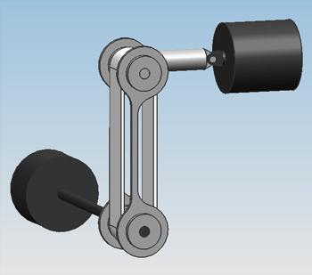
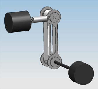
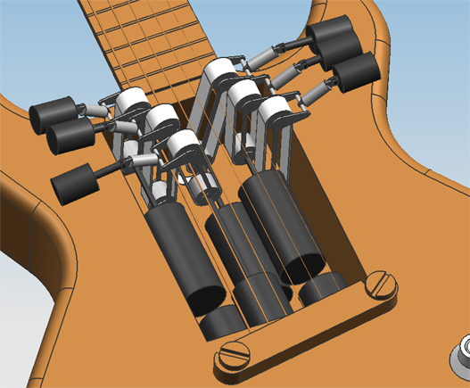
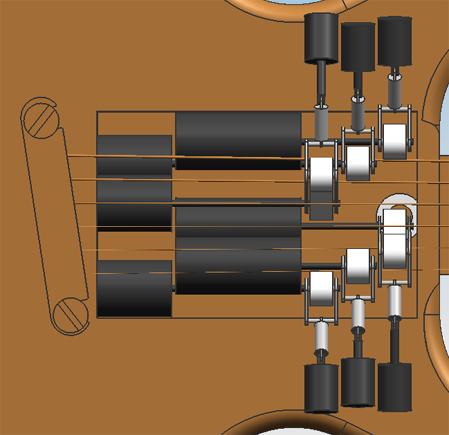
These improvements have been worked into design 0.2. | These improvements have been worked into design 0.2. Some CAD screenshots of this design are shown in the figure below. | ||
| Line 97: | Line 87: | ||
==Design 0.3 to 0.6== | ==Design 0.3 to 0.6== | ||
For the rest of the development of the design, many more considerations had to be made. For instance, we had to know what motors to use, what actuators to use, what roller bearings to use, shaft couplings, hinges, frames, etcetera. The most important design considerations are described in the paragraphs below. | |||
====Estimation of the required motor power==== | ====Estimation of the required motor power==== | ||
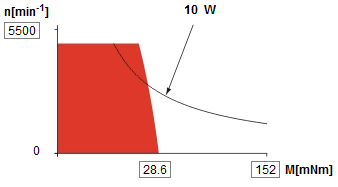
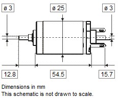
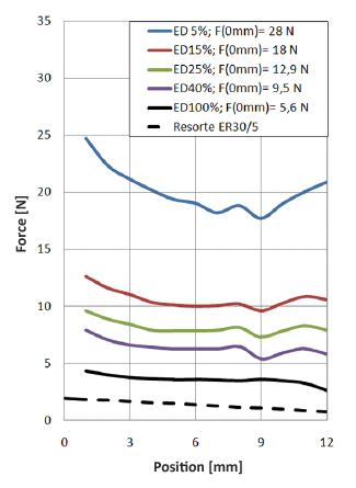
The needed motor power is calculated using <math>P=M_{T}\cdot\Omega</math>. For this, the total load <math>M_{T}</math> and the angular speed <math>\Omega</math> have to be calculated. The total motor load consists of the load coming from the friction of the bowing belt with the string <math>M_{bt}</math> and the friction of the bearing supporting the wheel that drives the belt, <math>M_{br}</math>. <math>M_{bt}</math> is calculated by <math>M_{w}=R\cdot F_{w,bt}=R\cdot F_{n}\cdot\mu_{w,bt}</math>, with <math>F_{n}=F_{b}</math> the normal force between the bowing belt and the string. This bow force has a maximum of <math>4 N</math>. The value of <math>\mu_{w,bt}</math> is estimated at a rather high <math>0.7</math>. The radius <math>R</math> at which the belt runs around the shafts is taken to be <math>7.5 mm</math>, on the actual design it will be smaller than this. This yields <math>M_{bt}=21.0 mNm</math>. | The needed motor power is calculated using <math>P=M_{T}\cdot\Omega</math>. For this, the total load <math>M_{T}</math> and the angular speed <math>\Omega</math> have to be calculated. The total motor load consists of the load coming from the friction of the bowing belt with the string <math>M_{bt}</math> and the friction of the bearing supporting the wheel that drives the belt, <math>M_{br}</math>. <math>M_{bt}</math> is calculated by <math>M_{w}=R\cdot F_{w,bt}=R\cdot F_{n}\cdot\mu_{w,bt}</math>, with <math>F_{n}=F_{b}</math> the normal force between the bowing belt and the string. This bow force has a maximum of <math>4 N</math>. The value of <math>\mu_{w,bt}</math> is estimated at a rather high <math>0.7</math>. The radius <math>R</math> at which the belt runs around the shafts is taken to be <math>7.5 mm</math>, on the actual design it will be smaller than this. This yields <math>M_{bt}=21.0 mNm</math>. | ||
| Line 167: | Line 159: | ||
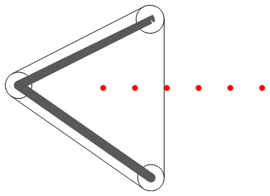
The situation is sketched in the figure below. | The situation is sketched in the figure below. | ||
{| align=center padding=0 cellspacing=0 style="background:#f9f9f9" width="480px" | {| align=center padding=0 cellspacing=0 style="background:#f9f9f9" width="480px" | ||
| Line 176: | Line 169: | ||
|- | |- | ||
|} | |} | ||
The figure clearly shows that having the non-bowing side of the belt run back upwards between the strings is no option whatsover, because the non-bowing side will run into another string (the middle string in the picture). If this isn't possible, it ''certainly'' isn't possible to fit a frame in between the strings. | The figure clearly shows that having the non-bowing side of the belt run back upwards between the strings is no option whatsover, because the non-bowing side will run into another string (the middle string in the picture). If this isn't possible, it ''certainly'' isn't possible to fit a frame in between the strings. | ||
Therefore, this configuration is dropped and a new one is adopted: we let the frame that holds the bowing belt run around the outermost strings, and with a third pulley, let the bowing belt run this way too. This configuration is sketched in the figure below. | Therefore, this configuration is dropped and a new one is adopted: we let the frame that holds the bowing belt run around the outermost strings, and with a third pulley, let the bowing belt run this way too. This configuration is sketched in the figure below. | ||
{| align=center padding=0 cellspacing=0 style="background:#f9f9f9" width="395px" | {| align=center padding=0 cellspacing=0 style="background:#f9f9f9" width="395px" | ||
| Line 189: | Line 184: | ||
|- | |- | ||
|} | |} | ||
<br> | |||
====Design of the claws==== | ====Design of the claws==== | ||
The claws were | The shape of the claws was designed in a very straightforward way. There were three pulleys, and a rod where a hinge can grip on, for the linear actuator. The lower and the "left" pulley are connected with a rib, and the "left" pulley with the upper pulley too. Then, the hinge rod is connected with the left pulley. Because this is the force path, the hinge rod is connected directly to the upper pulley too. For the "long" version of the claw, spacial restrictions dictate that the rib between the lower pulley and the left pully should be curved, to make place for a shaft of another mechanism. This doesn't cause problems, because there will be no direct compressing force between these pulleys. | ||
The claws were dimensioned in a number of steps: | |||
#We chose an estimate size for the claws, so that they fitted into the design. | #We chose an estimate size for the claws, so that they fitted into the design. | ||
| Line 197: | Line 195: | ||
#We changed the size of the claws to fit the bowing belts exactly. | #We changed the size of the claws to fit the bowing belts exactly. | ||
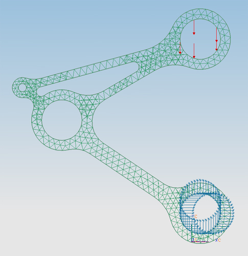
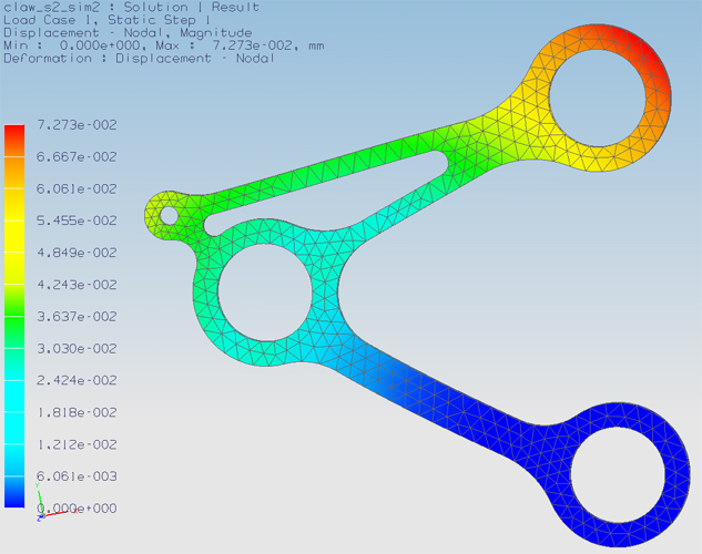
By fitting exactly, we mean that one pair of claws forming a sandwich should excite 4 N of force on the bowing belt, so it sits tightly around the pullies, and will be stiff enough when pressed against the string. This means one claw part will have to excite a force of 2 N. We made the claws a little too big. To be precise, we placed the hole for the upper pulley shaft 0.07 mm too high. FEM analysis in NX5 predicts that it will require a force of 2 N to bend the claw back to the propper dimensions. This is shown in the figure below. | By fitting exactly, we mean that one pair of claws forming a sandwich should excite 4 N of force on the bowing belt, so it sits tightly around the pullies, and will be stiff enough when pressed against the string. This means one claw part will have to excite a force of 2 N. We made the claws a little too big. To be precise, we placed the hole for the upper pulley shaft 0.07 mm too high. FEM analysis in NX5 predicts that it will require a force of 2 N to bend the claw back to the propper dimensions. This result was achieved by varying the width of the rib between the lower and the left pulley. This is shown in the figure below. | ||
| Line 208: | Line 206: | ||
|- | |- | ||
|} | |} | ||
<br> | |||
====Design 0.6==== | ====Design 0.6==== | ||
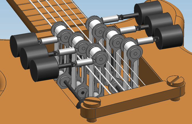
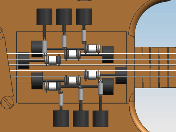
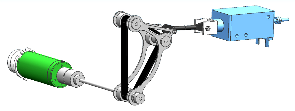
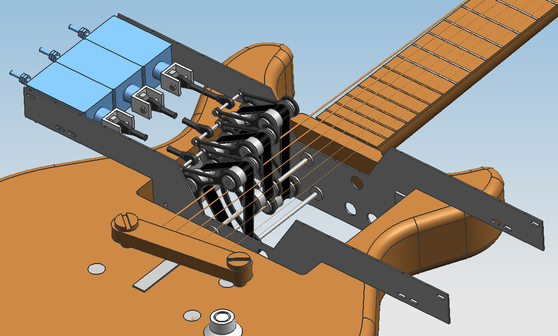
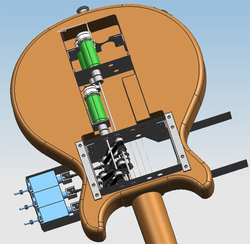
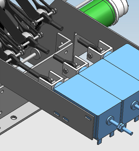
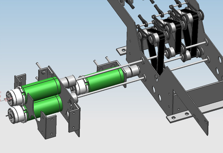
Below are many screenshots of the final design in CAD. Of this design, only 3 single-string mechanisms were actually realised, but the whole design is expandable to 6 mechanisms without problems. The frame has also been realized so that additional mechanisms can be assembled without alterations to the frame. | |||
{| align=center padding=0 cellspacing=0 style="background:#f9f9f9" width="395px" | |||
|- | |||
| style="font-size:85%; border:1px solid #cccccc; padding:3px 3px 0px 3px" | | |||
[[File:Design06img06.jpg|border]] | |||
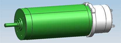
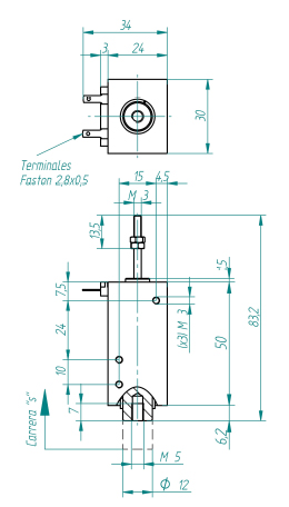
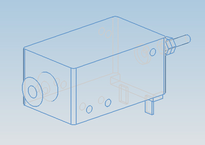
The resulting mechanism for a single string. The motor (green) and the linear actuator (blue) are fixed. The shaft of the motor is lengthened with a shaft coupling. All shafts in the claw frame are mounted with roller bearings. Between the linear actuator and the claws is a set of hinges, that are connected with an M2 threaded rod. The length of the shaft and this rod differs for the different mechanisms used to play the different strings. | |||
|- | |||
|} | |||
{| align=center padding=0 cellspacing=0 style="background:#f9f9f9" width="395px" | |||
|- | |||
| style="font-size:85%; border:1px solid #cccccc; padding:3px 3px 0px 3px" | | |||
[[File:Design06img01.jpg|border]] | |||
The guitar with the mechanism. The frame as well as the spacial configuration of the motors allows for 6 single string mechanisms to be built in, but only 3 mechanisms were actually realised, for budgetary reasons. | |||
|- | |||
|} | |||
{| align=center padding=0 cellspacing=0 style="background:#f9f9f9" width="964px" | |||
|- | |||
| style="font-size:85%; border:1px solid #cccccc; padding:3px 3px 0px 3px" | | |||
[[File:Design06img02.jpg|border]] [[File:Design06img03.jpg|border]] | |||
Left: The guitar shown from below. Right: Close up of the connection between the linear actuators and the claw frames. The rods between the hinges weren't modelled to keep the model more flexible, but the hinges are lined out as if the rods were there. | |||
|- | |||
|} | |||
{| align=center padding=0 cellspacing=0 style="background:#f9f9f9" width="395px" | |||
|- | |||
| style="font-size:85%; border:1px solid #cccccc; padding:3px 3px 0px 3px" | | |||
[[File:Design06img04.jpg|border]] | |||
The entire design including the frame shown without the guitar, shown from "below". | |||
|- | |||
|} | |||
<br> | |||
==Right-hand user interface== | ==Right-hand user interface== | ||
Latest revision as of 15:58, 23 March 2011
|
