PRE2015 4 Groep1: Difference between revisions
| (186 intermediate revisions by 5 users not shown) | |||
| Line 1: | Line 1: | ||
<!--Hier is markup cheatsheet--> | <!--Hier is markup cheatsheet--> | ||
<!--([https://en.wikipedia.org/wiki/Help:Cheatsheet Wiki markup cheatsheet])--> | <!--([https://en.wikipedia.org/wiki/Help:Cheatsheet Wiki markup cheatsheet])--> | ||
{{TOC limit}} | |||
__FORCETOC__ | __FORCETOC__ | ||
== Group members == | == Group members == | ||
*Laurens | *Laurens van der Leden - 0908982 | ||
*Thijs | *Thijs van der Linden - 0782979 | ||
*Jelle Wemmenhove - 0910403 | *Jelle Wemmenhove - 0910403 | ||
*Joshwa Michels - 0888603 | *Joshwa Michels - 0888603 | ||
*Ilmar van Iwaarden - 0818260 | *Ilmar van Iwaarden - 0818260 | ||
== Project Description == | == Project Description == | ||
| Line 41: | Line 40: | ||
== Planning == | == Planning == | ||
'''Week 1''' | '''Week 1''' | ||
* Create presentation | |||
* Determine concept idea of a hugging robot | |||
* determine users | |||
'''Week 2''' | |||
* Determine use aspects | |||
* Create presentation | |||
* Create planning | |||
* Re-create scenario | |||
2 | |||
- | |||
'''Week 3''' | '''Week 3''' | ||
* Investigate Amigo robot | |||
** discuss options with staff | |||
** acquire access to Amigo [Milestone] | |||
** look up general info software/hardware [Milestone] | |||
* Purchase additional materials/objects | |||
* Literature HTI | |||
** identify critical problems | |||
** tele-presence, situational-awareness, elders | |||
* Update wiki | |||
'''Week 4''' | |||
'''Week 4''' | * Amigo robot | ||
** program structure [Milestone] | |||
** send/receive signals [Milestone] | |||
* Literature HTI | |||
** identify critical problems [Milestone] | |||
** Identify use aspects | |||
* Update wiki | |||
'''Week 5''' | |||
'''Week | * Amigo robot | ||
** get input from Kinect [Milestone] | |||
** add telephone functionality | |||
* Literature HTI | |||
** tele-presence, situational-awareness, elders | |||
* Update wiki | |||
'''Week 6''' | |||
* Amigo robot | |||
** control Amigo arms [Milestone] | |||
** add telephone functionality [Milestone] | |||
* Literature HTI | |||
** Search for information regarding force feedback | |||
** Search for information regarding use aspects | |||
* Update wiki | |||
'''Week 7''' | |||
* Amigo robot | |||
** test with dummy [Milestone] | |||
** implement feedback | |||
* USE-aspects | |||
** scenario analysis (Social Robots) [Milestone] | |||
* Update wiki | |||
'''Week 8''' | |||
* Amigo robot | |||
** human test [Milestone] | |||
* Buffer | |||
* Prepare Presentation | |||
* Update wiki | |||
'''Week 9''' | |||
* Final rehearsal [Milestone] | |||
* Buffer | |||
* Final update wiki [Milestone] | |||
== Milestones project == | == Milestones project == | ||
''' Robot building/modifying process ''' | |||
'''1. Get robot skeleton'''<br /> | '''1. Get robot skeleton'''<br /> | ||
We have to acquire a robot mainframe we can modify in order to make a robot that has the functions we want it to have. Building an entire robot from scratch is not possible in eight weeks. If the owners allow us we can use the robot Amigo for this project. <br /> | We have to acquire a robot mainframe we can modify in order to make a robot that has the functions we want it to have. Building an entire robot from scratch is not possible in eight weeks. If the owners allow us we can use the robot Amigo for this project. <br /> | ||
| Line 132: | Line 134: | ||
After the robot is Kinect driven we must modify it in order to be fully working according to plan. In this case it must be able to perform hugs exactly as we want it. As a real shadow of ourselves. <br /> | After the robot is Kinect driven we must modify it in order to be fully working according to plan. In this case it must be able to perform hugs exactly as we want it. As a real shadow of ourselves. <br /> | ||
'''Wiki ''' | |||
'''5. Have a complete wiki page of what was done''' <br /> | '''5. Have a complete wiki page of what was done''' <br /> | ||
This milestone means that we simply have to possess a wiki page which describes our project well. <br /> | This milestone means that we simply have to possess a wiki page which describes our project well. <br /> | ||
''' Literature ''' | |||
'''6. State of the art''' <br /> | '''6. State of the art''' <br /> | ||
Find useful articles about existing shadow robotics and hugging robots. <br /> | Find useful articles about existing shadow robotics and hugging robots. <br /> | ||
=== Evaluation === | |||
'''Completed Milestones'''<br/> | |||
'Most of the milestones were completed as the project was in progress. We managed to make a deal with Tech United, who allowed us to use their robot AMIGO for the project, but instructed us to practice and test with a simulator first, before applying our created code and scripts on the real AMIGO. With that we had our robot to be used '''(1)'''. | |||
Over the course of the weeks we learned to work with Robot Operating Software or ROS for short, the programming software used for AMIGO or at least the functions we needed to proceed '''(2)'''. As for all materials required we had most of the required materials once we acquired the used AMIGO files and installed ROS. Other things we needed in the end would be a Kinect and software that could process the data perceived by the Kinect. Since we would mainly use digital software and one of our group members, Jelle, had a Kinect at home, we didn't need to order any further materials '''(3)'''. | |||
Once we learned how to work with the simulator we learned several commands that could make the robot perform certain actions '''(4a)'''. We could later link these commands to data perceived by the Kinect and put through to ROS '''(4b)'''. This allowed us to let the robot shadow actions performed by a person standing in front of the Kinect interface, albeit only for the arms and due to internet connection with some delay '''(4d)'''. | |||
At the end of the project we put every part of information concerning our project we deemed important on the Wiki in order to give a good view of what we had done in our project '''(5)'''. | |||
Ilmar and Thijs spent a lot of time searching for literature and articles about our subject and what already existed in this area of robotics. Some of theses articles proved useful for our project or at least the description of the idea '''(6)'''. These articles can be found under '''Research'''. | |||
'' | '''Failed Milestones'''<br/> | ||
We did not manage to include the telephone function in our prototype, mainly because other parts of the design had more priority and we were running out of time '''(4c)'''. While the telephone function was not the most important thing we wanted to include it is certainly a part of the project that should be included in a more advanced version of our prototype. | |||
'''Conclusion regarding Milestones'''<br/> | |||
Overall nearly all our milestones were completed with relative success during the course of the project, the sole exception being the telephone function. It is unfortunate that this milestone was not completed, but it did not ruin the project as we still had something fun to demonstrate to the public and learned a lot from the project. Failing to complete any other milestone would have resulted in bigger problems as those would have resulted in significant problems for the project. | |||
''' | |||
== Research == | == Research == | ||
| Line 335: | Line 195: | ||
* Both the robots Paro and Telenoid proved that robots are able to improve the mood of elderly people, by encouraging them to have more conversations. | * Both the robots Paro and Telenoid proved that robots are able to improve the mood of elderly people, by encouraging them to have more conversations. | ||
=== | === Literature === | ||
*'''Telenoid''' | *'''Telenoid''' | ||
| Line 433: | Line 293: | ||
It is always good to have a set of ground rules about social robots, and to whether your robot concept satisfies those rules. Other than those basic set of rules/requirements, the artic was not that useful as the title let me expect it would be. | It is always good to have a set of ground rules about social robots, and to whether your robot concept satisfies those rules. Other than those basic set of rules/requirements, the artic was not that useful as the title let me expect it would be. | ||
==== Force feedback ==== | |||
In order to establis a exchange of forces that make a hug more comfortable than a static envellopment by the arms, some research is done into force feedback. We hope that this will help to make a hug more realistic and enjoyable. | |||
Although force feedback was researched, implementation in the model was not succesfull due to its complexity. A position feedback control is used instead. See [http://cstwiki.wtb.tue.nl/index.php?title=PRE2015_4_Groep1#Simulink_model_2| Simulink model] | |||
Used Literature: | |||
http://link.springer.com.dianus.libr.tue.nl/article/10.1007%2Fs12555-013-0542-6 | |||
http://servicerobot.cstwiki.wtb.tue.nl/files/PERA_Control_BWillems.pdf | |||
http://www-lar.deis.unibo.it/woda/data/deis-lar-publications/d5aa.Document.pdf | |||
''Regeltechniek'', M. Steinbuch & J.J. Kok | |||
''Modeling and Analysis of Dynamical systems'', Charles M. Close & Dean H. Frederick & Honathan C. Newell. 3th edition | |||
''Engineering Mechanics ,Dynamics'', J.L. Meriam & L.C. Kraige | |||
''Mechanical Vibrations'', B. de Kraker | |||
http://www.tandfonline.com/doi/pdf/10.1163/016918611X558216 | |||
http://ieeexplore.ieee.org/xpl/articleDetails.jsp?arnumber=5174779&newsearch=true&queryText=Control%20of%20haptic%20and%20robotic%20telemanipulation%20systems | |||
http://ieeexplore.ieee.org/stamp/stamp.jsp?tp=&arnumber=5246502 | |||
Max Baeten, ''Implementing compliant control on PERA manipulator'' [http://servicerobot.cstwiki.wtb.tue.nl/files/Final_Thesis_Max_Baeten.pdf pdf] | |||
https://www.cs.rpi.edu/twiki/pub/RoboticsWeb/ReadingGroup/Impedance_Controller.pdf | |||
http://publications.lib.chalmers.se/records/fulltext/142739.pdf | |||
== Used Literature/Further reading == | == Used Literature/Further reading == | ||
=== | ==== Exploring Possible Design Challenges ==== | ||
*'''Advances in Telerobotics''' | *'''Advances in Telerobotics''' | ||
| Line 450: | Line 344: | ||
http://www.sciencedirect.com.dianus.libr.tue.nl/science/article/pii/0005109889900939 | http://www.sciencedirect.com.dianus.libr.tue.nl/science/article/pii/0005109889900939 | ||
This | This article discusses the historical developments in telerobotics and current and future applications of the technology. Different interfaces and control architecters are discussed. Its focus however is not on hardware or software but on robot-human interaction. | ||
This | This article is useful as an introduction into telerobotics. There are no practical uses conserning software or hardware, and there might be some conserning USE aspects, although the article might be slightly outdated. | ||
*'''An Intelligent Simulator for Telerobotics Training''' | *'''An Intelligent Simulator for Telerobotics Training''' | ||
| Line 458: | Line 352: | ||
http://ieeexplore.ieee.org.dianus.libr.tue.nl/xpl/abstractAuthors.jsp?arnumber=5744073&tag=1 | http://ieeexplore.ieee.org.dianus.libr.tue.nl/xpl/abstractAuthors.jsp?arnumber=5744073&tag=1 | ||
This | This article discusses a architecture for path planning and learning and training. This might be useful for future research and development of the hugging robot, but it is not for the scope of this project. | ||
*'''Telerobotic Pointing Gestures Shape Human Spatial Cognition''' | *'''Telerobotic Pointing Gestures Shape Human Spatial Cognition''' | ||
| Line 476: | Line 370: | ||
This paper discusses the importance of haptics in telerobotics. It gives an introduction to haptics, telerobotics and telepresence. The paper is not very useful other than introducing the reader to these subject. Any implementation of haptics might be to complicated to acieve with Amigo. | This paper discusses the importance of haptics in telerobotics. It gives an introduction to haptics, telerobotics and telepresence. The paper is not very useful other than introducing the reader to these subject. Any implementation of haptics might be to complicated to acieve with Amigo. | ||
=== | == Experiment measuring force in hug == | ||
=== Motivation === | |||
For most humans, hugging is a very easy activity to perform, that is generally performed as a greeting shortly at the beginning and end of a rendezvous in an informal setting (i.e. a rendezvous with friends/relatives). When the relationship between two people is closer, it also occurs that these people hug each other during rendezvous and longer/more intense, where there is a bigger want to express the mutual (friendly) feelings towards each other. This up to the point of two hugging lovers, where one would actually refer to as cuddling rather than hugging. As a result, one can expect that within our situation sketch of close relatives/friends on a long distance, there is quite a want for hugging not only shortly as a greeting but even more to express the mutual feelings. | |||
Moreover, as the hug becomes longer, intense and more personal; it also gets carried out more ‘subtle’. For humans, this performance of gently touching each other is rather obvious, the majority of the people does this intuitional and have the motorics to do so. For a robot, all this is not obvious at all. Therefore, it is necessary to translate this intuitive notion of a hug to an abstract level feasible for the robot. In order to do this, this experiment was conducted that would quantify the gentile, ‘subtle’ touching of the hug (i.e. how tight the hug should be) into an amount of force graphed against the elapsed time. | |||
=== Set-up experiment === | |||
'''Used accessories:''' | |||
* 3 ‘FlexiForce’ strip sensors | |||
* Regulation instrument on PCB (Printed Circuit Board) | |||
* ‘SEL’ Interface (processing and transforming signal) | |||
* Interface USB cable | |||
* Power cable | |||
* Software “Meetpaneel” | |||
* Rubber band | |||
* Wooden splint (as subsurface for the FlexiForce sensors) | |||
* Scotch tape | |||
'''The experiment consists of two parts:''' | |||
1. Measuring the force on the lower part of the arm | |||
2. Measuring the force on the upper part of the arm | |||
'''The set-up is as follows:''' | |||
First, all the cables are put in to place such that the interface is working properly and software “Meetpaneel” is downloaded and booted such that the laptop can receive signals. The three flexiforce strip sensors get attached to the wooden splint using the scotch tape (see photo 1). This is to prevent the sensors from moving (and sending incorrect data). Then, the splint with the sensors and the regulation instrument are put on Ilmar’s arm (part 1 of the experiment his lower arm, part 2 his upper arm) using the rubber band, and the ‘flexiforce’ sensors get plugged in the regulation instrument (see photo 2). The regulation instrument converts the three signals of the sensors into one signal; it takes the mean of the three incoming sensors. Now, the signal is ready to be processed by the laptop, but not yet to be displayed properly. To display it in the right way, some final adjustments in the program “Meetpaneel” like scaling should be made. Finally, everything was set-up and the hug could begin. (photo 3) | |||
{|style="margin: 0 auto;" | |||
| [[File:Experiment_photo_1.jpg|400px|thumb|right|Photo 1: General overview of the set-up]] | |||
| [[File:Experiment_Hug_Photo_2.jpg|400px|thumb|right|Photo 2: Close-up of the regulation instrument]] | |||
| [[File:Experiment_Hug_Photo_3.jpg|200px|thumb|right|Photo 2: Close-up of the regulation instrument]] | |||
|} | |||
=== Analysing data === | |||
''Note: We will not do the exact calculations here, since they are straightforward and we already did them in the excel file, which can be found [https://www.dropbox.com/s/6fag4uvdozsy2vz/Excelfile%20Verwerkte%20data%20experiment%20USE.xlsx?dl=0 HERE] . Instead, we will describe precisely how we analysed '' | |||
The raw data we get in “Meetpaneel” from the “Flexiforce” sensors is the voltage measured at a time instance; so in particular, it consists of a set of points with these two quantities. Because we are interested in the behaviour of the force overtime rather than the voltage overtime, we need to convert this quantity. To do so, we assumed a linear relation between the two quantities in the sensor. Then, we acquired two data points: the first point being the amount of Volt when no object was lying on the sensor (so 0 Newton force) and the second point the amount of Volt when 500 gram was lying on each of the sensors (so 0,5*9,81=4,905 Newton). Through these two points, one can fit exactly one straight line and with some basic math the formula of this line can be calculated (y=13.32413868*x-0.515065113 where y is the force and x is the voltage). | |||
The set of force-time points obtained by this formula have negative as well as positive values. Although this behaviour might at first seem strange, one possible explanation is that the “Flexiforce” sensors behave in a way comparable to spring and that the negative values are a direct ‘reaction’ on the ‘action’ of the positive ones (Newton’s third law). This explanation agrees with the data, as the negative force points are not clustered together, but instead are always preceded by positive points of approximately the same size. Because of this phenomenon and the fact that we are interested in the magnitude of the force rather than the sign, it makes sense to take the absolute value of the force per point and plot that instead of the original force. | |||
=== Results & conclusion === | |||
The graphs of respectively the force on the upper arm and the lower arm are shown down below. | |||
By a first look at the graphs, it is very clear when the hug starts and ends and that there is no significant difference between the lower part of the arm and the upper part (the small differences can be explained by the fact that we the data comes from two different hugs). More importantly, one can see that the magnitude of the force during the hug is not constant, but varies over time. This variation seems not to be random, but it has a sort of periodic, quasi oscillating behaviour (like a difficult sine function). | |||
The main conclusion to be drawn from this is the following: If one wants to mimic the gentile, ‘subtle’ and personal hugging done by humans, one should respect this quasi periodic, oscillating behaviour. To be more specific, the arms of the robot should be programmed in such a way that the robot first hugs the user more loosely, than more closely, more loosely, etcetera. Also, it seems a good idea to but a little variation in play of hugging closely and loosely. This is to prevent the hug from becoming an repetitive exact copy of movements, which would probably feel uncanny as it is too ‘mechanic’. | |||
{|style="margin: 0 auto;" | |||
| [[File:Graph hug upper part arm (force vs time).png|thumb|500px|Graph 1: hug upper part arm (force vs time)]] | |||
| [[File:Graph hug lower part arm (force vs time).png|thumb|500px|Graph 2: hug lower part arm (force vs time)]] | |||
|} | |||
== Simulink model == | |||
As the ROS simulation didn't give any information or feedback in respect to the acting forces, a simulink model is created. For this simulation the physical aplication has to be translated in to a mathematical model, before a controller can be designed. The model for the plant and the controller are created using Simulink. | |||
==== Simplyfication and Equation of motion ==== | |||
When discribing a hug, the horizontal movement of the arms is more dominant than the vertical movement. Therefor we considered the move to be 2D in the x-y plane. This has the disadvantage that gravitational forces are not included in the model, and thus somewhat less accurate. Because of symmetry, it suffices to only discribe one arm. This arm will consist of an upper and a lower arm, for simplification the hands are not included in the model. | |||
When creating a mathematical model, first the free body diagram is considered. | |||
As the robot moves both upper and lower arms independently with an independent motor, the corresponding plant consist of one arm. The plant can than be described with the balans of moments. | |||
[[File:Isolated body.JPG|thumb|Free body diagram of the lower arm]] | |||
:<math display block> | |||
\sum M = \frac{1}{2} F_1 L_1 + T \dot{\theta_1} + K \theta_1 + M_2 = I_0 \ddot{\theta_1} | |||
</math> | |||
In this formula <math display inline>F_1</math> is the force pressing on the arm at half its length <math display inline>L_1</math>, <math display inline> T </math> is the friction coefficient that discribes the friction in the joints, <math display inline> K </math> is the stifness in the arm itself and <math display inline> I_0 </math> is the inertia of the arm. The reaction moment from the upper arm working on the lower arm is added in the form of , <math display inline> M_2 </math>. The inertia can be calculated because the mass <math display inline> m_1 </math> and the length of the arm are known. | |||
:<math display block> | |||
I_0 = m_1 L_1 ^2 | |||
</math> | |||
This is discription is then implemented in simulink as shown in the figure. The values of the parameters were found in [http://servicerobot.cstwiki.wtb.tue.nl/files/Final_Thesis_Max_Baeten.pdf pdf]. | |||
{| class="wikitable" | |||
|- | |||
! Parameter | |||
! Value | |||
|- | |||
| <math display inline> m_1 </math> | |||
| 0.86 kg | |||
|- | |||
| <math display inline> L_1 </math> | |||
| 0.28 m | |||
|- | |||
| <math display inline> T </math> | |||
| 3 Nm/s | |||
|- | |||
| <math display inline> K </math> | |||
| 1400 N | |||
|} | |||
With this a controller can be designed. | |||
{| style="margin: 0 auto;" | |||
|- | |||
| [[File:Simuplant.JPG|thumb|The plant of the upper arm.]] | |||
| [[File:Simumodel.JPG|thumb|The simulink model for one part of the arm.]] | |||
|} | |||
==== Simulink model ==== | |||
From the equation of moment balans, a discription for the plant can be discribed. By applying the La Place transformation the following plant discription can be derived. | |||
:<math display block> | |||
Plant=\frac{1}{I_0 s^2 + T s + K } | |||
</math> | |||
In order to | In order to make the hug comfortable, some requirements are set for the hug. From the experiment we learned that the forces alternated at a high frequency and that these forces have a maximum of ''KIJKEN'' Newton. It is also necessary that the controller is stable and will not overshoot in the applied force in order to not hurt the user. | ||
As the forces are more important than the position of the arm, force control is prefered to position control. | |||
Force feedback control was investigated, but because of its complexity and a lack of time it couldn't be implemented in the model. A position feedback control is created instead. In order to make sure the forces from the controler don't get to big, a saturation block is used, which is set at a value of 30. This is in correspondance with the experiment, where a maximum value of 30 N was found during a hug. | |||
A PID controler <math display inline> C </math> is designed to control the system. | |||
:<math display block> | |||
C=\frac{K_d s^2 + K_p s + K_i }{s} | |||
</math> | |||
{| class="wikitable" | |||
|- | |||
! Parameter | |||
! Value | |||
|- | |||
| Kp | |||
| 1193 | |||
|- | |||
| Ki | |||
| 532.6 | |||
|- | |||
| Kd | |||
| 79.36 | |||
|} | |||
With this controler, the force output from the controler is then checked by plotting the output over the time. For this a step is used for input to mimick the user pushing against the robot arm. This step initiates at <math display inline> t = 3 </math> with an end value of 25. The first peak allows for the high frequency alternation in forces, while after that the force reduces to allow the user to push the arm away if necessary. | |||
[[File:Simuforce.JPG|center|Control output moment]] | |||
The open loop and closed loop are calculated as follows. | |||
:<math display block> | |||
H=C \cdot Plant | |||
</math> | |||
:<math display block> | |||
Closed = \frac{H}{1+H} | |||
</math> | |||
With this a bode plot and a Nyquist plot are created. As the graph passes the point <math display inline> (-1,0) </math> on the right side,it can be stated that the controler is stable. | |||
{| style="margin: 0 auto;" | |||
| [[File:Bode hug.jpg|left|Bode plots]] | |||
| [[File:Nyquist hug.jpg|right|Nyquist plots]] | |||
|} | |||
==== Discussion and Future research==== | |||
For the hugging robot, AMIGO was used as a reference. AMIGO has two arms with both an upper and a lower arm. In the simulink model, however, only one part of the arm is included. This is because both parts have each their own motor and different characteristics, which means different plant. This would mean that each part would require a different controler. But using two controlers becomes increasingly complex and further prove is needed before the system can be considered stable. | |||
As a result the used simulink model is only an approximation of a hugging robot. The reaction moment from the upper arm for example is not included in this model. | |||
To improve the model, the moment from the upper arm should be added. Numerous attempts were made to include this, but as the model could not be made stabe this was left out. | |||
Furter improvements can include a force feedback control or impedance control, in contrary to the used position feedback control. Research was done in the hope to include impedance control, but was found too complex to be implemented. | |||
== Technical Aspects == | |||
=== Requirements AMIGO === | |||
==== Exact Usage Scenario ==== | |||
The aim of this section is to provide an exact description of a hug that the AMIGO robot needs to perform during the final demonstration. | |||
'''Assumptions''' | |||
* The AMIGO robot’s shoulders are lower than the hug-receiver’s shoulders. | |||
* The hug-sender has a clear view of the AMIGO robot and the hug-receiver without any cameras. | |||
* The hug-sender can see what the AMIGO’s main camera sees using a display. | |||
'''Hug description''' | |||
# The hug-sender and the hug-receiver have already established a communication session via telephone. | |||
# The hug-receiver turns the AMIGO robot on. | |||
# The hug-sender turns the KINECT system on. | |||
# The hug-sender performs several test movements: by taking several poses focused on the hug-sender’s arms and checking whether the AMIGO robot’s arms take on the same poses. | |||
# The hug-sender spreads their arms to indicate they are ready to give the hug. The AMIGO robot also spreads its arms. | |||
# Both the hug-sender as well as the hug-receiver are notified that a hug can now be given. This can be done for example by changing the AMIGO’s color or having it pronounce a certain message. | |||
# The hug-receiver approaches the AMIGO robot. | |||
# The hug-receiver begins to hug the AMIGO robot (a so-called ‘bear’-hug). | |||
# The hug-receiver tells the hug-sender that they are ready to receive a hug from the AMIGO. | |||
# The hug-sender makes a hugging movement by closing their arms. | |||
# The AMIGO robot takes over after the hug-sender’s arms have reached a certain point. This is because the hug-sender cannot see the hug-receiver and the AMIGO’s arms clearly enough to give the hug-receiver a comfortable hug. | |||
# By measuring the resistance through the AMIGO’s actuators, the AMIGO can estimate the amount of pressure being exerted on the hug-receiver. The AMIGO starts to slowly close its arms around the hug-receiver, starting with its upper arms and ending with the hands. | |||
# (optional) By moving its arms closer together or farther apart, the hug-sender can make the AMIGO robot hug tighter or looser. | |||
# The hug-sender or the hug-receiver indicates that they would like to end the hug. | |||
# The AMIGO robot slowly spreads its arms outwards. | |||
# The hug-receiver stops hugging the robot and walks away. | |||
# The AMIGO robot and the KINECT system are turned off. | |||
==== Must-Should-Could-haves ==== | |||
''' Must-have ''' | |||
* The AMIGO must be able to process the arm-movements of the hugging person in considerable time (ideally in real time, but probably unrealistic) and mimic them credible and reasonable fluently to the person ‘to be hugged’. | |||
* The arms of the AMIGO must be able to embrace the person ‘to be hugged’. More specifically; the AMIGO must be able to make an embracing movement with his arms. | |||
''' Should-have ''' | |||
* There should be a force-stop function in the AMIGO so that the person ‘to be hugged’ can stop the hug anytime if he/she desires (for example because he/she feels uncomfortable). | |||
* The AMIGO should have a feedback function as to if and how much his arms are touching a person (pressure sensors). | |||
''' Could-have ''' | |||
* The AMIGO could get a message from the ‘hug-giver’, the person in another place wanting to give a hug. | |||
* The AMIGO could inform the ‘hug-receiver’ that a hug has been ‘send’ to him/her and ask if he/she wants to ‘receive’ the hug now. | |||
* The AMIGO could receive a message from the ‘hug-giver’ that the hug has ended. | |||
=== ROS === | |||
The predefined simulator of AMIGO is used for this project. This simulator runs in Robotic Operating System or ROS. ROS is programming software used for many robot projects and can not be ran in Windows (yet). Since all the work in on AMIGO in ROS is done in the control system Ubuntu 14.04, this was the control system we installed for the project. | |||
[[File:AMIGOscreenshot.png|thumb|right|400px|AMIGO's robot model as seen in the ROS simulator]] | |||
All functions for controlling the AMIGO robot in the simulator as well as its main environment are already defined and could be downloaded from GitHub. The only things we had to figure out were certain commands to move the arms and process these in a script. This can be done with some predefined operations. We used Python as a programming language and based on a template we created a [[AMIGO ROS Script|script]] that can control the arms of amigo based on data from the Kinect. This script can be executed in the Terminal and will send orders to the simulator as long as the simulator is activated. The simulator can be started by typing the following commands in loose terminals. <br/> | |||
-''roscore'', this command will activate the ROS master and the network of nodes. Without this the script and the simulator can't communicate. <br/> | |||
-''astart'', this is a command that will launch a file that starts up certain parts of the AMIGO simulator. <br/> | |||
-''amiddle'', this is a second command that will launch a file that starts up the rest of the AMIGO simulator and the world models. <br/> | |||
-''rviz-amigo'', this will start a visualizer that shows the robot model and its environment. This can be used to see what the robot is doing. <br/> | |||
The arm control function used for our simulation is ''Amigo.leftarm.default_trajectories'' and ''Amigo.rightarm.default_trajectories'' . These commands work as follows. In the part about AMIGO's degrees of freedom and Coordinates conversion is discussed that AMIGO has seven joints in his arms that can be rotated with a certain amount. ''Amigo.lefarm.default_trajectories'' and ''Amigo.leftarm.default_trajectories'' can be used to predefine a certain sequence of positions for the seven joints in respectively the left and right arm of the robot. The previously defined sequences of poses can be executed with the commands “Amigo.leftarm.send_joint_trajectory” and “Amigo.rightarm.send_joint_trajectory”. These commands send the sequences for the arms to the simulator and AMIGO will then move his arms in the given positions. | |||
A ROS node is a small part of a program in ROS with a certain function. ROS nodes can communicate with each other through ROS topics. This can be compared with two mobile devices communicating with each other through a certain frequency. A node can send certain messages or instruction through a topic and another node can receive this messages and carry out the instructions. | |||
The AMIGO simulator can be seen as a node and our script that can send the commands is a node as well that sends the commands over a topic to be received by the simulator node. | |||
The script used will receive an array size 1x14 with 14 numbers in it from the computer housing the Kinect software, derived from Kinect data. This array will be send over the topic and the script is written in such a way that it can receive this array and process it to two 1x7 arrays that will be the coordinates of the arm joints for the two arms of AMIGO. The script in windows will continuously send a new array with numbers based on the data derived of the Kinect. This way the script will continuously receive data which it will then process and send to the simulator. This way AMIGO will continously adjust its arm poses to the poses of the person in front of the Kinect interface. More on how this works is discussed under '''Kinect''' and '''Connection ROS-Kinect'''. | |||
---- | |||
===Kinect=== | |||
In order to imitate the hug the hug-sender is making, it is necessary to capture the movements of their body. To do so we needed some kind of motion capturing device and we chose the Kinect V2 technology from Microsoft. This technique was designed to translate poses made by humans into video games and therefore we deemed it well suited to translating someone’s arm movements into data that the AMIGO robot could use to imitate the hug. Above all we could easily access this motion sensing device as one of our group members already owned one. | |||
This section describes how use the Kinect’s input to let the AMIGO copy the hug-sender’s arm motions. | |||
====AMIGO’s degrees of freedom==== | |||
[[File:Amigo_DOF.JPG|thumb|right|250px|The DOF of AMIGO]] | |||
The AMIGO uses two PERA manipulators as arms that have seven degrees of freedom each. Imitating a hug with AMIGO’s arms requires that we send it the correct information it needs to copy the hug-sender’s arm poses. What follows is a short description of the motions governed by each degree of freedom for the left arm. Note that this description of the degrees of freedom of the right arm is a mirror image of this description. We used [http://servicerobot.cstwiki.wtb.tue.nl/files/Final_Thesis_Max_Baeten.pdf Max Baeten’s final thesis] as guide to explain the different degrees of freedom. | |||
{|style="margin: 0 auto;" | |||
| [[File:Part1 q1.jpg|thumb|250px|First Degree of Freedom]] | |||
| [[File:Part1 q2.jpg|thumb|250px|Second Degree of Freedom]] | |||
| [[File:Part1 q3.jpg|thumb|250px|Third Degree of Freedom]] | |||
|} | |||
'''Q1''' | |||
The first degree of freedom is the angle that determines how far the arm is raised sideways. When the arm is not raised, the angle is 0. The arm can only be raised up to the point that it is fully pointing out, it cannot be raised any higher, resulting in an upper limit of <math display inline>0.5 \pi</math>. For some reason however, the angle is given as a negative number (meaning that a fully raised arm corresponds to an angle of <math display inline> - 0.5 \pi </math>). | |||
'''Q2''' | |||
The second degree of freedom is the angle that determines whether the arm points forwards or backwards. It should be seen as the angle between the torso of the person and the projection of the arm onto the side of the person. In combination with the first degree of freedom this angle defines the direction the upper arm is pointing in. It’s range is between <math display inline> - 0.5 \pi </math> (backwards) and <math display inline> 0.5 \pi </math> (forwards). | |||
'''Q3''' | |||
The third degree of freedom determines how much the upper arm is rotated over its own main axes, also known as its roll. It can reach from <math display inline> -0.5 \pi </math> to <math display inline> 0.5 \pi </math> where a positive value represents an inward rotation and a negative value represents an outward rotation. This rotation partially determines the direction the lower arm points towards when the elbow is bent. | |||
{|style="margin: 0 auto;" | |||
| [[File:Part1 q4.jpg|thumb|250px|First Degree of Freedom]] | |||
| [[File:Part1 q5.jpg|thumb|250px|Second Degree of Freedom]] | |||
| [[File:Part1 q6.jpg|thumb|250px|Third Degree of Freedom]] | |||
| [[File:Part1 q7(2).jpg|thumb|250px|Third Degree of Freedom]] | |||
|} | |||
'''Q4''' | |||
The fourth degree of freedom concerns the angle at which the elbow is bent. An angle of 0 corresponds to a fully stretched arm whereas an angle of 2.23 corresponds to the maximum angle at which the AMIGO’s elbow can be bent. | |||
'''Q5''' | |||
The fifth degree of freedom is comparable to the third, though it represents the roll of the lower arm. It can vary from -1.83 to 1.83 with a positive angle indicating that the lower arm is rotated inwards. It partially controls the direction the hand is pointing towards. | |||
'''Q6''' | |||
The sixth degree of freedom determines the angle at which the wrist is bend in the direction of the palm of the hand. It ranges from -0.95 to 0.95. An angle of 0 corresponds to a stretched wrist and a positive angle means that the hand is bent in the direction of the palm. | |||
'''Q7''' | |||
The seventh and final degree of freedom controls the angle the hand is rotated about the direction the hand’s palm is facing. It is best described as trying to make a waving motion sideways whilst not moving the lower or upper arm. It varies from -0.61 to 0.61 where an angle of zero represents no rotation. A positive angle corresponds to an anti-clockwise rotation when looking at the palm of the (left) hand. | |||
====Extracting data from the Kinect sensor==== | |||
The [https://www.microsoft.com/en-us/download/details.aspx?id=44561 SDK of Kinect] comes with predefined functionality to retrieve information about the ‘skeleton’ of the users the Kinect is [https://msdn.microsoft.com/en-us/library/jj131025.aspx tracking]. These skeletons are representations of the position and [https://msdn.microsoft.com/en-us/library/hh973073.aspx orientaton] of the user’s joints e.g. [https://msdn.microsoft.com/en-us/library/microsoft.kinect.jointtype.aspx shoulders and knees]. Several examples of code are provided by Microsoft and can be downloaded together with the SDK. We used the position of these joints in [https://msdn.microsoft.com/en-us/library/windowspreview.kinect.cameraspacepoint.aspx camera space] to calculate the angles needed to emulate the hug-sender’s arms in the AMIGO. Below it is explained how each of these angles were calculated for the left arm. The c++ code used to do this can be found [http://cstwiki.wtb.tue.nl/index.php?title=AMIGO_Kinect_Script here]. Note that because c++ does come with a standard library for vectors and vector manipulation we needed to define our own vector class and several standard vector operations. Finally, in the code a lot of vectors are named using the following convention: the first two letters of the joint it is pointing from, the number 2 as the word ‘to’ and the first two letters of the joint is pointing towards. | |||
{|style="margin: 0 auto;" | |||
| [[File:Part2 q1.jpg|thumb|250px|Calculation of first Degree of Freedom]] | |||
| [[File:Part2 q2.jpg|thumb|250px|Calculation of second Degree of Freedom]] | |||
| [[File:Part2 q3.jpg|thumb|250px|Calculation of third Degree of Freedom]] | |||
|} | |||
'''Q1''' | |||
Let <math display inline> \boldsymbol{a} </math> be the vector pointing from the shoulder to the elbow and let <math display inline> \boldsymbol{b} </math> be the vector pointing to the left of the person (this can be calculated by taking the difference between the position of the left and right shoulder). Let <math display inline> U </math> be a plane perpendicular to <math display inline> \boldsymbol{b} </math>, this represents the side of the person. The first angle is equal to the angle between <math display inline> \boldsymbol{a} </math> and its projection <math display inline> \mathcal{P}_U(\boldsymbol{a}) </math>. Because of the strange decision to let the angle be given in a negative number, it should be multiplied by -1. | |||
'''Q2''' | |||
Let <math display inline> \boldsymbol{c} </math> be the vector pointing down the left side of the body. Let <math display inline> \boldsymbol{d} </math> be the vector pointing forwards from the left shoulder, <math display inline> \boldsymbol{d} = \boldsymbol{c} \times \boldsymbol{a} </math>. The second angle is then equal to the angle between the projection <math display inline> \mathcal{P}_U(\boldsymbol{a}) </math> and <math display inline> \boldsymbol{c} </math>. To determine whether the angle should be positive or negative, take the dot product between <math display inline> \boldsymbol{a} </math> and <math display inline> \boldsymbol{d} </math>. The sign of the angle is equal to the sign of this dot product. | |||
'''Q3''' | |||
The third angle is a bit more difficult to determine. Let <math display inline> \boldsymbol{e} </math> be the vector pointing from the elbow to the wrist. Let <math display inline> V </math> a plane perpendicular to the vector <math display inline> \boldsymbol{a} </math>. The third angle is equal to the angle between the projections <math display inline> \mathcal{P}_V(\boldsymbol{d}) </math> and <math display inline> \mathcal{P}_V(\boldsymbol{d}) </math>. To determine the sign of the angle it is necessary to define another vector. Let <math display inline> \boldsymbol{f} </math> be the cross product between the two projections, <math display inline> \boldsymbol{f} = \mathcal{P}_V(\boldsymbol{d}) \times \mathcal{P}_V(\boldsymbol{e}) </math>. <math display inline> \boldsymbol{f} </math> points in the same direction as <math display inline> \boldsymbol{a} </math> when the rotation is positive and in the opposite direction when it is negative. This means that the sign of the angle is the same as the sign of the dot product of <math display inline> \boldsymbol{a} </math> and <math display inline> \boldsymbol{f} </math>. | |||
'''Q4''' | |||
The fourth angle simply is the angle between the vectors <math display inline> \boldsymbol{a} </math> and <math display inline> \boldsymbol{e} </math>. | |||
'''Q5''' | |||
The fifth angle can be calculated in a similar way as the third angle. Let <math display inline> \boldsymbol{g} </math> be the vector pointing from the wrist to the tip of the hand. Furthermore, let <math display inline> W</math> be a plane perpendicular to <math display inline> \boldsymbol{e} </math>. The angle is equal to the angle between the projections of <math display inline> -\boldsymbol{a} </math>and <math display inline> \boldsymbol{g} </math> on <math display inline> W </math>. To determine the sign we take the cross product <math display inline> \boldsymbol{h} = \mathcal{P}_W(-\boldsymbol{a}) \times \mathcal{P}_W(\boldsymbol{g})</math>. The sign of the angle is equal to the sign of the dot product between <math display inline> \boldsymbol{e} </math> and <math display inline> \boldsymbol{h} </math>. | |||
'''Q6''' | |||
The sixth angle is calculated similarly as the fourth angle. It is equal to the angle between the vectors <math display inline> \boldsymbol{e} </math> and <math display inline> \boldsymbol{g} </math>. It should be noted that the sign of the angles should be determined, but we had forgotten to do so. | |||
'''Q7''' | |||
Some attempts were made to determine the seventh angle, but we did not succeed in this. We are of the impression that this does not have any major consequences for the hug however. It is a very specialized, local motion whereas a hug is performed using the entire arm. Secondly, the motion can be recreated by changing the upper arm’s roll. | |||
=== Connection between ROS and Kinect === | |||
==== Sending data to ROS ==== | |||
The SDK for Kinect we used to calculate the angles of the hug-sender’s arms runs on a Windows machine whilst the AMIGO’s software runs on Ubuntu 14.04. These two operating systems are not easily combined. There are several solutions to this problem: | |||
* We can run the Ubuntu system in a virtual machine on the Windows machine. We chose not to pursue this option as we did not have any experience which such a construction and because we feared that it would decrease the system’s performance. | |||
* There are several drivers and libraries to make the Kinect run on an Ubuntu machine. An example of these is [https://msdn.microsoft.com/en-us/library/dn188670.aspx Kinect Fusion]. However, this particular library is not well suited to capturing dynamic human poses. It was made to be able to navigate static environments. We looked at other libraries such as [http://structure.io/openni OpenNI], but we decided that it would be easier to just use the official Microsoft libraries on a Windows machine. A major influence on this decision was the fact that we had already found another solution, which brings us to the next solution. | |||
* We can send data from the Windows machine to the Ubuntu machine over a network. The [http://wiki.ros.org/rosserial_windows/Tutorials/Hello%20World rosserial windows] package for ROS deals with the complicated network stuff (e.g. sockets) and lets the user publish ROS messages on a ROS topic on the Ubuntu machine. This solution also fits our conceptual technique better. The point of our hugging robot is that the hug-sender and hug-receiver can hug each other whilst being separated by a large distance. | |||
By having a Windows application publish the angles calculated as a single message onto a ROS topic, we can create a ROS node that subscribes to this topic and uses the angles calculated to operate the arms. To use this code, a rosserial socket node needs to be run on the Ubuntu machine for it to be able to receive messages via a network. This is explained in more detail in the [http://wiki.ros.org/rosserial_windows/Tutorials/Hello%20World rosserial tutorial] | |||
==== Sending data between Windows applications ==== | |||
Two different applications are used to take input from the Kinect sensor and manipulate its data into the angles that control the AMIGO’s arms and to send the data to the Ubuntu machine. It would not be desirable to have such a construction in the final product, but we faced some compatibility issues merging the two applications. Instead we used a sloppy method to transfer data from the first application to the second. The first application writes to a text-file and the second one reads from the same text-file. We had tried to use pipelines to send data, but we lacked proper knowledge of c++ to get it to work. | |||
=== scripts === | |||
These are links to separate pages explaining the different scripts created to make the prototype work. | |||
* [http://cstwiki.wtb.tue.nl/index.php?title=Kinect_Angles_Calculation_Script Calculating the angles from the <code>Joint</code> data structure.] | |||
* [http://cstwiki.wtb.tue.nl/index.php?title=Sending_data_between_Windows_Applications&action=edit&redlink=1 Sending the data between Windows applications.] | |||
* [http://cstwiki.wtb.tue.nl/index.php?title=Rosserial_Script Sending the data to the Ubuntu machine.] | |||
* [http://cstwiki.wtb.tue.nl/index.php?title=AMIGO_ROS_Script Using the data to control the AMIGO’s arms.] | |||
A download link of all the different projects can be found [https://www.mediafire.com/?o8vdy2t2tf5mqlv here]. | |||
== Evaluation == | |||
During the project of designing our hugging robot and creating a potential prototype we had a lot of things where we learned from and would do differently if we had to do it over. The first thing was that we focused too much on getting amigo to work. We were all new with using robots in general and therefore we were really enthusiastic that there was a possibility of using the amigo robot. Due to this tunnel vision we forgot one of the most important if not the most important factor of a hug: the continuous amount of forces that get applied on the bodies during a hug. We were so caught up in getting the motion and position right using Kinect, that we forgot about the forces and did not see its importance until late in the project. Therefor we did the force experiment and created the Simulink model too late into the project and on top of it, we figured that the simulator that we were running did not support forces. This could all have been prevented if we made a sketch of the hug that we wanted to give and of what was happening during a hug. | |||
Another thing that could have done better was the efficiency of the way we installed Ubuntu and the ROS simulator. We had as Mr. Molengraft said “two horses running on the same path”, both trying to figure out how to install ROS individually. With better communication and planning, this could have gone a lot smoother, where one team member could figure out how to install it and then explain it to the others. Where the other members could have done something different in the meantime. | |||
One of the things that we are really proud of is the fact that we wanted to get Kinect working in combination with amigo’s software from the beginning of the project and that we indeed got that working. It might even be usable for amigo in the future or NAO. | |||
Starting this project, we all had no experience of what to do with such a big project without a guiding hand of the university, and I can safely say that it was a great experience for us all and that we truly learned something. | |||
=== Interesting Links === | |||
Some interesting links and other sources for anyone interested in copying a users movements with Kinect, hugs or shadow robotics. | |||
https://www.youtube.com/watch?v=KnwN1cGE5Ug | https://www.youtube.com/watch?v=KnwN1cGE5Ug | ||
| Line 524: | Line 749: | ||
https://www.shadowrobot.com/products/air-muscles/ | https://www.shadowrobot.com/products/air-muscles/ | ||
Latest revision as of 22:37, 20 June 2016
Group members
- Laurens van der Leden - 0908982
- Thijs van der Linden - 0782979
- Jelle Wemmenhove - 0910403
- Joshwa Michels - 0888603
- Ilmar van Iwaarden - 0818260
Project Description
The aim of this project is to create a anthropomorphic robot that can be used to hug others when separated by a large distance. This robot will copy or shadow a hugging movement performed by a human using motion capture sensors. In order to realize this goal the robot AMIGO will (if allowed and possible) be used to perform the hugs while the commandos are generated using Kinect sensors that capture movement done by a human.
USE Aspects
Before designing the hugging robot it is important to analyze what are the benefits and needs of the users, the society and the enterprises. What might drive them to invest in the technology and what are their needs and wishes?
Who are the USE?
- Primary users: As the hugging robot intended use is to connect people that are separated from each other, the main primary users will be separated from their loved ones for a longer period. As such the primary user will be mainly elderly people, distant relatives or friends, and children or students.
- Secondary users: As primary users want to use the hugging robot, the secondary users will be instances where lot of the primary users can be found. As such hugging robots will be used by nursing or care homes and hospitals, private or boarding schools and educational instances that hold many international students like universities.
- Tertiary users: The hugging robot will probably be in high demand and being used many times by maybe different people. Therefore there will be a demand for maintenance. The tertiary user will be the maintenance staff as a result.
- Society: As the hugging robot will be placed in many government instances, national and local government will be the one that distributes the technology.
- Enterprise: The enterprises that will benefit from the hugging robot are the companies that will help produce the hugging robot. As such the virtual-reality enterprises and the robot producing companies are to benefit from this technology.
What are the needs of the USE?
- Primary user needs: As a large part of the primary users might new technology maybe complicated or intimidating, the hugging robot has to be safe physically as well as psychologically and easy to use. The fact that people are hugging the robot requires that it is comfortable to touch.
- Secondary user needs: As the secondary users are likely to have more than one robot, they would prefer a relatively cheap price. As they probably cannot afford to educate people to become experts with the robot, the robot has to be easy to install and use. A educational instance could reserve a room for the hugging robot, but in a hospital or nursing home, the patient might not be able to move. In that case it must be possible to move the robot to the patient. Therefore the robot has to be not too big and not too heavy. The fact that multiple people will make use of one robot might give rise to the wish that the appearance of the robot is adaptable.
- Tertiary user needs: As the robot has to be relatively cheap, the maintenance of the robot cannot be very intensive. This will require the robot to be easily cleaned and broken hardware and software to be easily accessible and replaced.
- Society needs: The hugging robot will be a device to connect people over large distances, in a better way than modern communication devices can. As such it will fight against loneliness and help strengthen family values.
- Enterprise needs: For the companies it is vital that the hugging robot will make a profit and to achieve this, the robot must be cheap to produce.
How can we process these things in to the project.
- Safety: In order to not damage the primary users the robot has to have pressure sensors for making sure the hug is comfortable and not painful. As an approaching robot might be frightening, the robot cannot give a hug until the user will allow. And by giving the robot an easy to reach kill switch, the user will not be trapped in case the robot might malfunction.
- Comfortable: To make sure the user will enjoy the hug, the robot has to have a soft skin that might be made of cushions and cannot be cold to the touch. By giving the robot a tablet, which might show a photo of the relative, and portraying a similar voice to that of the relative, we hope to make the user more at ease when alone with the robot. Dressing the robot in clothes and playing background music or sounds can also add to that effect. Giving the robots interface two separate buttons for phone function and movement activation, gives the user the choice whether or not he might want the robot to hug him and serves to give the user the sense that he is in control.
- Easy to use: As most people are already familiar with telephone functions, we want to design an interface that is as simple as that.
- Adaptable appearance: The robot can have a set of clothes and/or different skins to adapt to different situations.
Planning
Week 1
- Create presentation
- Determine concept idea of a hugging robot
- determine users
Week 2
- Determine use aspects
- Create presentation
- Create planning
- Re-create scenario
Week 3
- Investigate Amigo robot
- discuss options with staff
- acquire access to Amigo [Milestone]
- look up general info software/hardware [Milestone]
- Purchase additional materials/objects
- Literature HTI
- identify critical problems
- tele-presence, situational-awareness, elders
- Update wiki
Week 4
- Amigo robot
- program structure [Milestone]
- send/receive signals [Milestone]
- Literature HTI
- identify critical problems [Milestone]
- Identify use aspects
- Update wiki
Week 5
- Amigo robot
- get input from Kinect [Milestone]
- add telephone functionality
- Literature HTI
- tele-presence, situational-awareness, elders
- Update wiki
Week 6
- Amigo robot
- control Amigo arms [Milestone]
- add telephone functionality [Milestone]
- Literature HTI
- Search for information regarding force feedback
- Search for information regarding use aspects
- Update wiki
Week 7
- Amigo robot
- test with dummy [Milestone]
- implement feedback
- USE-aspects
- scenario analysis (Social Robots) [Milestone]
- Update wiki
Week 8
- Amigo robot
- human test [Milestone]
- Buffer
- Prepare Presentation
- Update wiki
Week 9
- Final rehearsal [Milestone]
- Buffer
- Final update wiki [Milestone]
Milestones project
Robot building/modifying process
1. Get robot skeleton
We have to acquire a robot mainframe we can modify in order to make a robot that has the functions we want it to have. Building an entire robot from scratch is not possible in eight weeks. If the owners allow us we can use the robot Amigo for this project.
2. Learn to work with its control system
Once we have the “template robot” we have get used to its control system and programming system. We must know how to edit and modify things in order to change its action.
3. Get all the required materials for the project
A list has to be made that includes everything we need to order or get elsewhere to execute the project. Then everything has to be ordered and collected.
4. Write a script/code to make the AMIGO do what you want
We will have to program the robot or edit the existing script of the robot to make it do what we want. This includes four stages:
4a Make it perform certain actions by giving certain commands
We must learn to edit the code to make sure the robot executes certain actions by entering a command directly.
4b Make sure these commands are linked to Kinect
Once we have the robot reacting properly on our entered commands we have to make sure these commands are linked to Kinect. We must ensure that the robot executes the action as a result of our own movements.
4c Include a talk function that gives the robot a telephone function
The robot must be armed with a function so that it reproduces word spoken by the man controlling it. This is like a telephone.
4d Make sure the robot is fully able to hug at will (is presentable to the public)
After the robot is Kinect driven we must modify it in order to be fully working according to plan. In this case it must be able to perform hugs exactly as we want it. As a real shadow of ourselves.
Wiki
5. Have a complete wiki page of what was done
This milestone means that we simply have to possess a wiki page which describes our project well.
Literature
6. State of the art
Find useful articles about existing shadow robotics and hugging robots.
Evaluation
Completed Milestones
'Most of the milestones were completed as the project was in progress. We managed to make a deal with Tech United, who allowed us to use their robot AMIGO for the project, but instructed us to practice and test with a simulator first, before applying our created code and scripts on the real AMIGO. With that we had our robot to be used (1).
Over the course of the weeks we learned to work with Robot Operating Software or ROS for short, the programming software used for AMIGO or at least the functions we needed to proceed (2). As for all materials required we had most of the required materials once we acquired the used AMIGO files and installed ROS. Other things we needed in the end would be a Kinect and software that could process the data perceived by the Kinect. Since we would mainly use digital software and one of our group members, Jelle, had a Kinect at home, we didn't need to order any further materials (3).
Once we learned how to work with the simulator we learned several commands that could make the robot perform certain actions (4a). We could later link these commands to data perceived by the Kinect and put through to ROS (4b). This allowed us to let the robot shadow actions performed by a person standing in front of the Kinect interface, albeit only for the arms and due to internet connection with some delay (4d).
At the end of the project we put every part of information concerning our project we deemed important on the Wiki in order to give a good view of what we had done in our project (5).
Ilmar and Thijs spent a lot of time searching for literature and articles about our subject and what already existed in this area of robotics. Some of theses articles proved useful for our project or at least the description of the idea (6). These articles can be found under Research.
Failed Milestones
We did not manage to include the telephone function in our prototype, mainly because other parts of the design had more priority and we were running out of time (4c). While the telephone function was not the most important thing we wanted to include it is certainly a part of the project that should be included in a more advanced version of our prototype.
Conclusion regarding Milestones
Overall nearly all our milestones were completed with relative success during the course of the project, the sole exception being the telephone function. It is unfortunate that this milestone was not completed, but it did not ruin the project as we still had something fun to demonstrate to the public and learned a lot from the project. Failing to complete any other milestone would have resulted in bigger problems as those would have resulted in significant problems for the project.
Research
State of the art
- Telenoid: The Telenoid robot is a small white human-like doll used as a communication robot. The idea is that random people and caregivers can talk to the elderly people from a remote location using the internet, and brighten the day of the elderly people by giving them some company. A person can control the face and head of the robot using a webcam, in order to give people the idea of a human-like presence. --[1 Telenoid]
- Paro: Paro is a simple seal robot, able to react to his surroundings, using minimal movement and showing different emotional states. It is used in elderly nursing homes to improve the mood of elderly people and with that reduce the workload of the nursing staff. Paro did not only prove that a robot is able to improve the mood of elderly people but also that a robot is able to encourage more interaction and more conversations.
- Telepresence Robot for interpersonal Communication (TRIC): TRIC is going to be used in an elderly nursing home. The goal of TRIC is to allow elderly people to maintain a higher level of communication with loved ones and caregivers than via traditional methods. The robot is small and lightweight so it is easy to use for the elderly people, it uses a webcam and a LCD screen.
Interesting findings from the literature research:
- Ways to create a human-like presence:
- Using a soft skin made of materials such as silicone and soft vinyl.
- Using humans to talk (teleoperate) instead of using a chat program, so the conversation are real and feel real.
- Unconscious motions such as breathing and blinking are generated automatically to give a sense that the android is a live.
- Minimal human design, so it can be any kind of person the user wants it to be using imagination. (Male/female, Young/old, Known person/Unkown person)
- From the participant’s view, the basic requirement for interpersonal communication using telepresence is that the participants must realize whom the telepresence robot represents. The two main options are using an LCD screen or to create mechanical facial expressions. (Mechanical facial expressions increase humanoid characteristics and therefore encourages more communication.)
- User requirements for the elderly:
- Affordable
- Easy to use:
- Lightweight
- Easy / Simple Interface
- Automatically Recharge
- Loud speakers (capable of 85dB), because elderly poeple prefer louder sounds for hearing speech sounds.
- Maximum speed of 1.2 m/s (Average walking speed)
- First of all it is important to know that whenever someone has a negative attitude towards robots, the robot will feel less human-like and increase the experienced social distance between humans and embodied agents. Secondly a proactive robot in this study was seen as les machine-like and more dependable when interaction was complemented with physical contact between the human and agent. Whenever people have a positive attitude towards robots, and the robot is proactive than the social experienced distance will decrease between humans and agents.
- Both the robots Paro and Telenoid proved that elderly people are able to accept robots. (9/10 of the people who used Telenoid accepted it, and thought the robot was cute)
- Both the robots Paro and Telenoid proved that robots are able to improve the mood of elderly people, by encouraging them to have more conversations.
Literature
- Telenoid
Telenoid 1 https://www.ituaj.jp/wp-content/uploads/2015/10/nb27-4_web_05_ROBOTS_usingandroids.pdf
This article is about the Telenoid robot. Here they mention that an ageing society with increasing loneliness is becoming a problem, “These days, the social ties of family, neighbors and work colleagues do not bond people together as closely as they used to and as a result, the elderly are becoming increasingly isolated from the rest of society. When elderly people become more isolated, they can lose their sense of purpose, become more susceptible to crime, and may even end up dying alone. Preventing isolation is essential if we are to create a safe and secure environment in the super-ageing society that Japan is having to confront ahead of any other country.”
In order to confront this isolation problem they developed the robot Telenoid, a communication robot. The idea is that random people and caregivers can talk to the elderly people from a remote location using the internet, and brighten the day of the elderly people by giving them some company. A person can control the face and head of the robot using a webcam, in order to give people the idea of a human-like presence.
These articles were useful because they give some interesting USE-aspects we could implement in our hugging robot. Like things that make a robot more humanlike. This article also showed us that the elderly people indeed react positive on human-robot interaction, this might not sound interesting but it was one of my biggest fears, that robot would not be accepted by the elderly people.
- Paro
Paro is a simple seal robot, able to react to his surroundings, using minimal movement and showing different emotional states. It is used in elderly nursing homes to improve the mood of elderly people and with that reduce the workload of the nursing staff. Paro did not only prove that a robot is able to improve the mood of elderly people but also that a robot is able to encourage more interaction and more conversations.
This article was not really useful, it just confirmed that robots can have a positive effect on people's mood and that it encourages conversations and interaction between the elderly people. I expected that this article would have been useful because every article or report about social robots cited this article and mentioned the robot "Paro".
- Telepresence Robot for interpersonal Communication
This article describes the development of a telepresence robot called TRIC ( Telepresence Robot for interpersonal Communication), who is going to be used in an elderly nursing home. The goal of TRIC is to allow elderly people to maintain a higher level of communication with loved ones and caregivers than via traditional methods. This paper further describes what discussion they made regarding the robot development process.
Interesting findings:
- From the participant’s view, the basic requirement for interpersonal communication using telepresence is that the participants must realize whom the telepresence robot represents. The two main options are using an LCD screen or to create mechanical facial expressions. (Mechanical facial expressions increase humanoid characteristics and therefore encourages more communication.)
- A telepresence robot should possess some form of autonomous behaviors. This is needed in order to be able to handle certain situations on its own, when the user does not know of this situation or is not able to control the robot properly.
- TRIC has the ability to automatically recharge its battery when needed.
- Affordable, lightweight and with a maximum speed of 1.2 m/s (walking speed)
- Loud speakers (capable of 85dB), because elderly people prefer louder sounds for hearing speech sounds.
We found a lot of interesting findings in this article, some which we can implement in our demonstration using the Amigo. The article also explains the definition of "telepresence" really well. We always thought that the robot had to feel like a human to the environment, but it is actually the other way around. The teleoperator has to feel as if he is physically in the same environment as the robot is.
- The effect of touch on people’s responses to embodied social agents
http://citeseerx.ist.psu.edu/viewdoc/download?doi=10.1.1.147.5975&rep=rep1&type=pdf
This study concluded a couple of things about the effect of physical contact between humans and robots. First of all, it is important to know that whenever someone has a negative attitude towards robots, the robot will feel less human-like and increase the experienced social distance between humans and embodied agents. Secondly, a proactive robot in this study was seen as less machine-like and more dependable when interaction was complemented with physical contact between the human and agent. Whenever people have a positive attitude towards robots, and the robot is proactive than the socially experienced distance will decrease between humans and agents.
Nothing too much out of the ordinary here, now we know that a proactive robot is more accepted than a reactive robot if it is about a robot touching a human. But unfortunately, the Amigo robot's movement are not quite what we would have liked, which would have made it a little bit awkward for the receiver if Amigo initiated the hug. Therefore we decided that we would program the Amigo robot to be reactive and let the receiver be the initiator here. Thus, the article was still useful, but only for our conceptual idea and not so useful for the actual demonstration.
- The Hug: An Exploration of Robotic Form For Intimate Communication
DiSalvo, C., Gemperle, F., Forlizzi, J., & Montgomery, E. (2003). The Hug: An Exploration of Robotic Form for Intimate Communication. Proceedings of the Ro-Man 2003. Millbrae. http://bdml.stanford.edu/twiki/pub/Haptics/TauchiRehabilitationProject/TheHugRobot.pdf
This article is about a robot called “the hug”. The hug is a pillow shaped robot with two outstretched arms and is made to support long distance communication between elderly and their relatives. They chose for a design that easily fits in a home context, the hug is soft and made from silk upholstered fabrics. It uses voice, vibration and heat patterns to create an intimate hug. Using two of these robots, people can chat and send each other hugs, when one is not available, voice messaged, heat patterns and vibration can be left and received later.
This article was useful because it gave us ideas for our own concept of a hugging robot. There are two main hugging robots available right now, where “the Hug” is one of them. What’s really interesting here is that using thermal fibers you can create a comfortable radiating warmth that makes a hug feel more natural. This is something we have speculated about but did have confirmed yet by the literature. What’s also interesting is that they did not chose to go for a humanlike robot, but chose for something that easily fits in a home context. Furthermore, we learned that stroking the back during a hug is really important to make it a real hug and that open outstretched arms invite and encourage people to hug a robot.
In our conceptual idea of our hugging robot, we could make use of thermal fibers and vibration as well, but unfortunately this is not possible with the Amigo robot. In Amigo’s case we can stretch out his arms to invite people to hug him, and we can try to make it possible to stroke someone’s back during the hug.
- Recognizing Affection for a Touch-based Interaction with a Humanoid Robot
Cooney, M. D., Nishio, S., & Ishiguro, H. (2012). Recognizing affection for a touch-based interaction with a humanoid robot. Paper presented at the 1420-1427.
In this article they talk about ways to recognize certain gestures and how affectionate these gestures are. They use two “mock-up” robots with touch sensors and a Microsoft Kinect camera to recognize these gestures. Some gestures were more easily recognized through the Kinect camera and others by the touch sensors. The gestures “Hug and pat back”, “hug” and “touch all over” were the most difficult gestures to recognize. The recognizing behavior was broken down in two sub problems: classifying gestures and estimating affection values. For the former they used Support Vector Machines, they also implemented the k-Nearest Neighbor algorithm. These all combined gave a high accuracy of 90.3%.
This article was useful for our conceptual idea of the hugging robot. Our conceptual hugging robot has to be proactive and initiate the hugging, therefor he needs to see and recognize what the receiver does. First we wanted to just use a Kinect camera, but this is clearly not enough. So now we are thinking about two Kinect camera’s and some touch sensors. For our demonstration using the amigo, it is not so useful. The Amigo robot is like he is and we are not allowed to change anything hardware related. Therefor we came up with the assumption that during the demonstration the hug sender is able to see the receiver and the robot at all times during the hug.
The Support Vector Machines are a subject that needs to be further looked into.
- MOTION CAPTURE FROM INERTIAL SENSING FOR UNTETHERED HUMANOID TELEOPERATION
http://citeseerx.ist.psu.edu/viewdoc/download?doi=10.1.1.85.2155&rep=rep1&type=pdf
Here they describe the motion suit made for the NASA robonaut using sensors with inertial measuring units (IMS). Here they explain that their suit is a cost-effective way of capturing motion while the current majority of commercial motion capture system are cost-prohibitive and have major flaws. This motion suit avoids those problems with the IMS sensors which only require gravity and the earth’s magnetic field to work. Their only limitation is the amount of sensors needed, other than that, they claim that this system is better than all the other systems. And that in the future this will play an important role in human-robot interaction research.
This article was interesting up to the fact that their system needs about 7 sensors for just the upper body half which costs approximately 300*7+100=2200$ for the sensors alone. Which becomes quite expensive when you consider that every relative who would like to use the hugging robot is going to have to buy this. The system is really interesting but way too expensive and therefore this article was not useful.
- The Hug Therapy Book
Kathleen Keating (1994). The Hug Therapy Book. Hazelden PES. ISBN 1-56838-094-1.
This book is all about hugs. The ethics and rules of conduct regarding hugs (Be sure to have permission, ask permission, be responsible etc.), the different kind of hugs (For example: Bear hug, side-to-side hug, heart-cantered hug, a-frame hug, etc.), the where, when and why (time of the day, environment, reasons to hug) and last but not least advanced techniques regarding hugs (Visualising, zen hugs).
This book really helped us out a lot, it is really hard to find literature that just explains what a hug is, or at least we were not able to find it. This book on the other hand is just that, it simply explains what a hug is, which is difficult for some people because it comes so natural for us. We were able to choose a type of hug for our concept namely the Bear hug thanks to this book (Definition of the bear hug follows below). This book also stated the importance of stroking once back during the hug and the warmth of a hug, which we read before in other articles as well.
The Bear Hug: " In the traditional bear hug (named for members of the family Ursidae, who do it best), one hugger usually is taller and broader than the other, but this is not necessary to sustain the emotional quality of bear-hugging. The taller hugger may stand straight or slightly curved over the shorter one, arms wrapped firmly around the other’s shoulders. The shorter of the pair stands straight with head against the taller hugger’s shoulder or chest, arms wrapped—also firmly!—around whatever area between waist and chest that they will reach. Bodies are touching in a powerful, strong squeeze that can last five to ten seconds or more. We suggest you use skill and forbearance in making the hug firm rather than breathless. Always be considerate of your partner, no matter what style of hug you are sharing. The feeling during a bear hug is warm, supportive, and secure.
Bear hugs are for: Those who share a common feeling or a common cause. Parents and offspring. Both need lots of reassuring bear hugs. Grandparents and grandoffspring. Don’t leave grandparents out of family bear hugs. Friends (this includes marrieds and lovers, who hopefully are friends too)." This makes it perfect for our concept and our demonstration.
- A Design-Centred Framework for Social Human-Robot Interaction
This article is about a framework for social human-robot interaction. They have five categories in there framework: form, modality, social norms, autonomy, interactivity. For each category they have basically three levels and for each of these categories they shortly explain what you should do when you are building a social robot. When looking at this framework for our hugging robot we should build for example a: Humanoid robot, because it is gonna act like a human and we want to give the impression that it could be a human (form), whereas for modality we do not really have those emotions and communication channels because the hugging robot is tele-operated, but you could imply that the robot needs to express the emotions of the teleoperator.
It is always good to have a set of ground rules about social robots, and to whether your robot concept satisfies those rules. Other than those basic set of rules/requirements, the artic was not that useful as the title let me expect it would be.
Force feedback
In order to establis a exchange of forces that make a hug more comfortable than a static envellopment by the arms, some research is done into force feedback. We hope that this will help to make a hug more realistic and enjoyable.
Although force feedback was researched, implementation in the model was not succesfull due to its complexity. A position feedback control is used instead. See Simulink model
Used Literature:
http://link.springer.com.dianus.libr.tue.nl/article/10.1007%2Fs12555-013-0542-6
http://servicerobot.cstwiki.wtb.tue.nl/files/PERA_Control_BWillems.pdf
http://www-lar.deis.unibo.it/woda/data/deis-lar-publications/d5aa.Document.pdf
Regeltechniek, M. Steinbuch & J.J. Kok
Modeling and Analysis of Dynamical systems, Charles M. Close & Dean H. Frederick & Honathan C. Newell. 3th edition
Engineering Mechanics ,Dynamics, J.L. Meriam & L.C. Kraige
Mechanical Vibrations, B. de Kraker
http://www.tandfonline.com/doi/pdf/10.1163/016918611X558216
http://ieeexplore.ieee.org/stamp/stamp.jsp?tp=&arnumber=5246502
Max Baeten, Implementing compliant control on PERA manipulator pdf
https://www.cs.rpi.edu/twiki/pub/RoboticsWeb/ReadingGroup/Impedance_Controller.pdf
http://publications.lib.chalmers.se/records/fulltext/142739.pdf
Used Literature/Further reading
Exploring Possible Design Challenges
- Advances in Telerobotics
AU: Manuel Ferre, Martin Buss, Rafael Aracil, Claudio Melchiorri, Carlos Balaguer ISBN: 978-3-540-71363-0 (Print) 978-3-540-71364-7 (Online) http://link.springer.com.dianus.libr.tue.nl/book/10.1007%2F978-3-540-71364-7
This book gives a discription of telerobotics and the advances within the field up to 2007. Several topics are discussed ranging form different interfaces, different control architectures and their performances to the applications of telerobotics. While the book starts with a general idea of each topic, the authors turn the text in depth soon after. This can make it hard to fully understand everything for readers not familiar with the field.
This book was partly useful as it gives a general idea about telerobotics, which is ultimately the foundation of the hugging robot. However it turns complicated fast, whereas not all topics discussed in the book are as useful, this resulted that their were no practical anwers found. Maybe the book will be more useful when designing the hug for the robot.
- Telerobotics
AU: T.B. Sheridan † http://www.sciencedirect.com.dianus.libr.tue.nl/science/article/pii/0005109889900939
This article discusses the historical developments in telerobotics and current and future applications of the technology. Different interfaces and control architecters are discussed. Its focus however is not on hardware or software but on robot-human interaction.
This article is useful as an introduction into telerobotics. There are no practical uses conserning software or hardware, and there might be some conserning USE aspects, although the article might be slightly outdated.
- An Intelligent Simulator for Telerobotics Training
AU: Khaled Belghith et al. http://ieeexplore.ieee.org.dianus.libr.tue.nl/xpl/abstractAuthors.jsp?arnumber=5744073&tag=1
This article discusses a architecture for path planning and learning and training. This might be useful for future research and development of the hugging robot, but it is not for the scope of this project.
- Telerobotic Pointing Gestures Shape Human Spatial Cognition
AU: John-John Cabibihan, Wing-Chee So, Sujin Saj, Zhengchen Zhang http://link.springer.com.dianus.libr.tue.nl/article/10.1007%2Fs12369-012-0148-9
This paper investigates the effect of pointing gestures in combination with speech in the design of telepresence robots. Can people interperter the gestures and does this inprove over time?
This paper is useful, as the hugging robot will have to make its intentions clear when it will try to hug a user. Hand gestures and pointing can play a large part in this. Based on the results of this paper, the hugging robot should have gestures incorporated in its request to make a hug.
- Haptics in telerobotics: Current and future research and applications
AU: Carsten Preusche , Gerd Hirzinger http://link.springer.com.dianus.libr.tue.nl/article/10.1007%2Fs00371-007-0101-3
This paper discusses the importance of haptics in telerobotics. It gives an introduction to haptics, telerobotics and telepresence. The paper is not very useful other than introducing the reader to these subject. Any implementation of haptics might be to complicated to acieve with Amigo.
Experiment measuring force in hug
Motivation
For most humans, hugging is a very easy activity to perform, that is generally performed as a greeting shortly at the beginning and end of a rendezvous in an informal setting (i.e. a rendezvous with friends/relatives). When the relationship between two people is closer, it also occurs that these people hug each other during rendezvous and longer/more intense, where there is a bigger want to express the mutual (friendly) feelings towards each other. This up to the point of two hugging lovers, where one would actually refer to as cuddling rather than hugging. As a result, one can expect that within our situation sketch of close relatives/friends on a long distance, there is quite a want for hugging not only shortly as a greeting but even more to express the mutual feelings.
Moreover, as the hug becomes longer, intense and more personal; it also gets carried out more ‘subtle’. For humans, this performance of gently touching each other is rather obvious, the majority of the people does this intuitional and have the motorics to do so. For a robot, all this is not obvious at all. Therefore, it is necessary to translate this intuitive notion of a hug to an abstract level feasible for the robot. In order to do this, this experiment was conducted that would quantify the gentile, ‘subtle’ touching of the hug (i.e. how tight the hug should be) into an amount of force graphed against the elapsed time.
Set-up experiment
Used accessories:
- 3 ‘FlexiForce’ strip sensors
- Regulation instrument on PCB (Printed Circuit Board)
- ‘SEL’ Interface (processing and transforming signal)
- Interface USB cable
- Power cable
- Software “Meetpaneel”
- Rubber band
- Wooden splint (as subsurface for the FlexiForce sensors)
- Scotch tape
The experiment consists of two parts:
1. Measuring the force on the lower part of the arm
2. Measuring the force on the upper part of the arm
The set-up is as follows:
First, all the cables are put in to place such that the interface is working properly and software “Meetpaneel” is downloaded and booted such that the laptop can receive signals. The three flexiforce strip sensors get attached to the wooden splint using the scotch tape (see photo 1). This is to prevent the sensors from moving (and sending incorrect data). Then, the splint with the sensors and the regulation instrument are put on Ilmar’s arm (part 1 of the experiment his lower arm, part 2 his upper arm) using the rubber band, and the ‘flexiforce’ sensors get plugged in the regulation instrument (see photo 2). The regulation instrument converts the three signals of the sensors into one signal; it takes the mean of the three incoming sensors. Now, the signal is ready to be processed by the laptop, but not yet to be displayed properly. To display it in the right way, some final adjustments in the program “Meetpaneel” like scaling should be made. Finally, everything was set-up and the hug could begin. (photo 3)
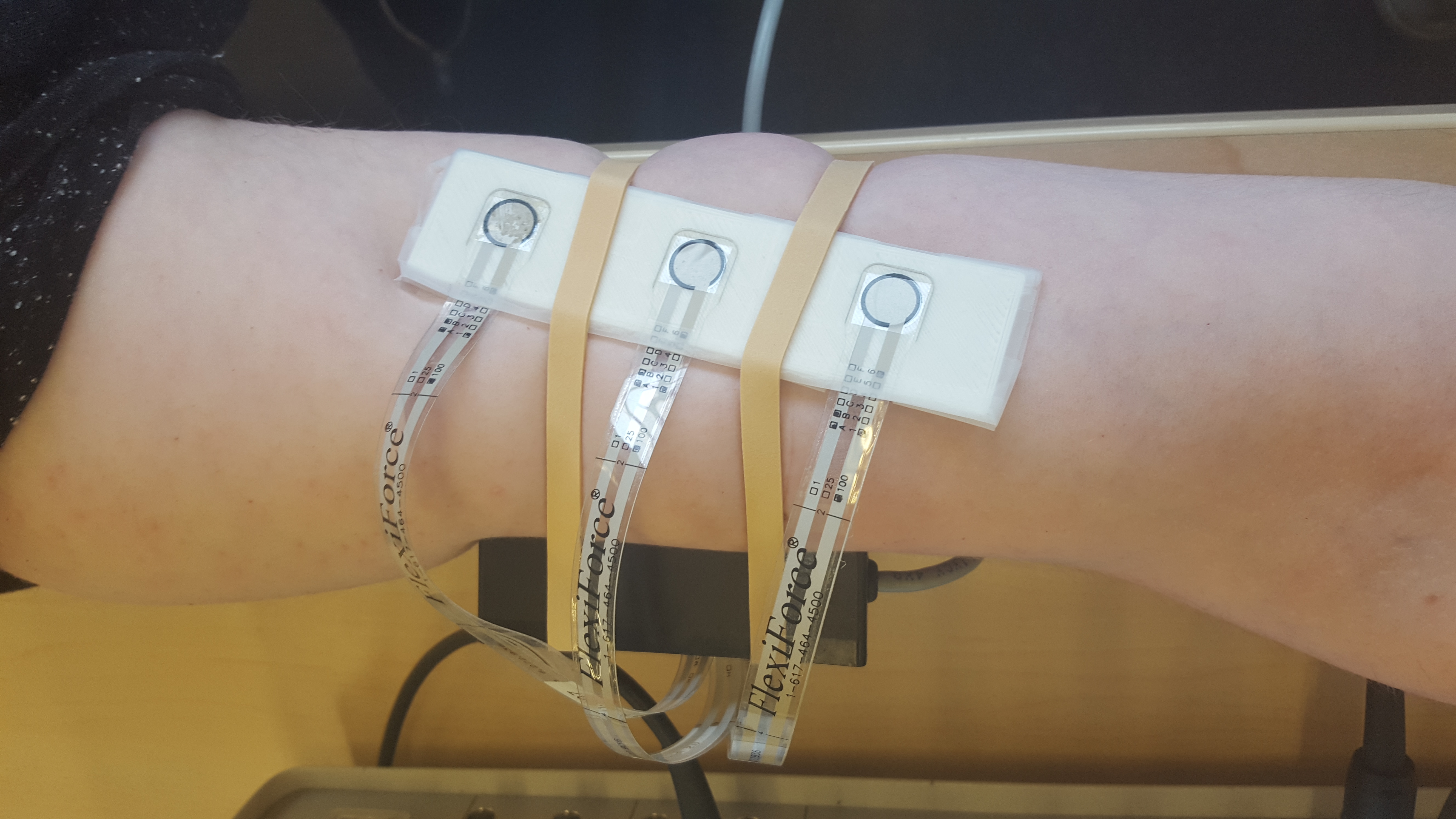 |
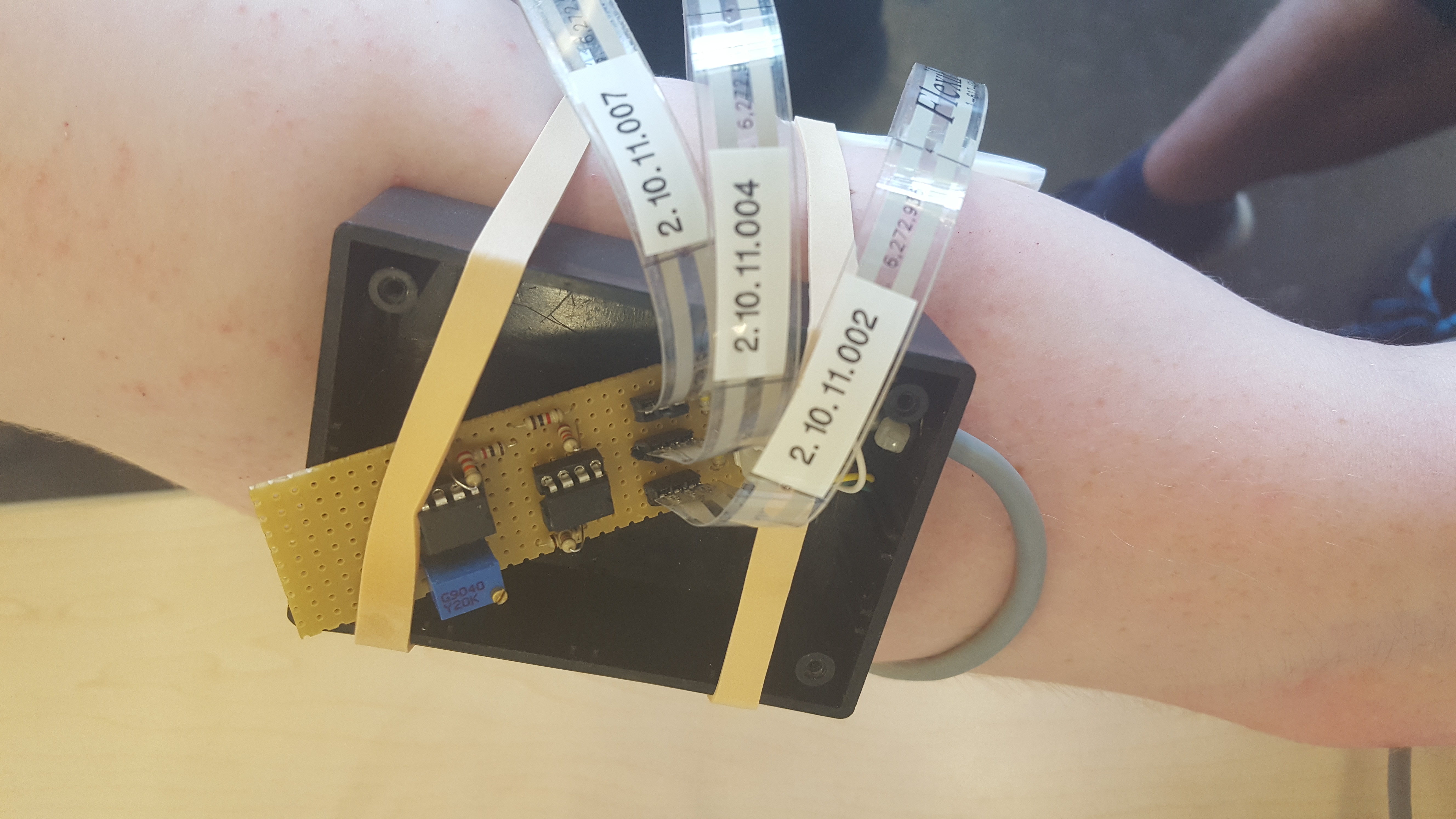 |
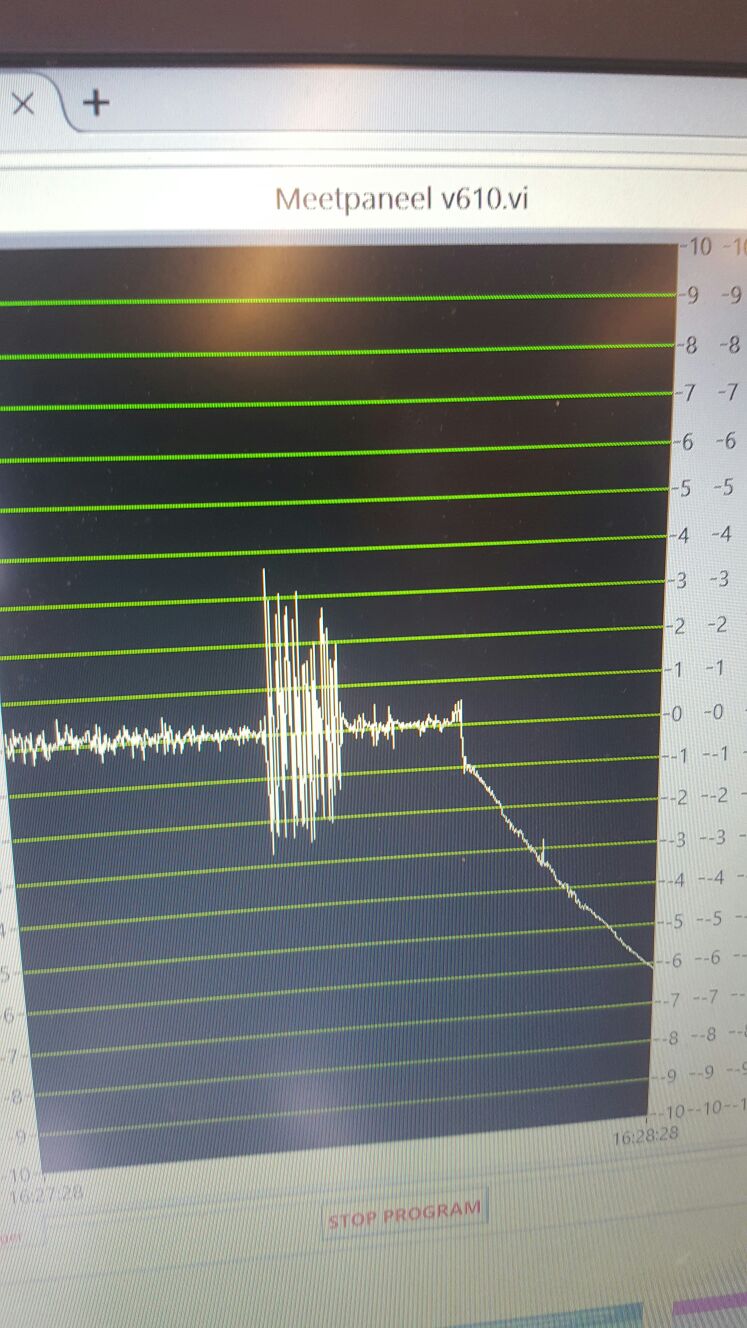 |
Analysing data
Note: We will not do the exact calculations here, since they are straightforward and we already did them in the excel file, which can be found HERE . Instead, we will describe precisely how we analysed
The raw data we get in “Meetpaneel” from the “Flexiforce” sensors is the voltage measured at a time instance; so in particular, it consists of a set of points with these two quantities. Because we are interested in the behaviour of the force overtime rather than the voltage overtime, we need to convert this quantity. To do so, we assumed a linear relation between the two quantities in the sensor. Then, we acquired two data points: the first point being the amount of Volt when no object was lying on the sensor (so 0 Newton force) and the second point the amount of Volt when 500 gram was lying on each of the sensors (so 0,5*9,81=4,905 Newton). Through these two points, one can fit exactly one straight line and with some basic math the formula of this line can be calculated (y=13.32413868*x-0.515065113 where y is the force and x is the voltage).
The set of force-time points obtained by this formula have negative as well as positive values. Although this behaviour might at first seem strange, one possible explanation is that the “Flexiforce” sensors behave in a way comparable to spring and that the negative values are a direct ‘reaction’ on the ‘action’ of the positive ones (Newton’s third law). This explanation agrees with the data, as the negative force points are not clustered together, but instead are always preceded by positive points of approximately the same size. Because of this phenomenon and the fact that we are interested in the magnitude of the force rather than the sign, it makes sense to take the absolute value of the force per point and plot that instead of the original force.
Results & conclusion
The graphs of respectively the force on the upper arm and the lower arm are shown down below.
By a first look at the graphs, it is very clear when the hug starts and ends and that there is no significant difference between the lower part of the arm and the upper part (the small differences can be explained by the fact that we the data comes from two different hugs). More importantly, one can see that the magnitude of the force during the hug is not constant, but varies over time. This variation seems not to be random, but it has a sort of periodic, quasi oscillating behaviour (like a difficult sine function).
The main conclusion to be drawn from this is the following: If one wants to mimic the gentile, ‘subtle’ and personal hugging done by humans, one should respect this quasi periodic, oscillating behaviour. To be more specific, the arms of the robot should be programmed in such a way that the robot first hugs the user more loosely, than more closely, more loosely, etcetera. Also, it seems a good idea to but a little variation in play of hugging closely and loosely. This is to prevent the hug from becoming an repetitive exact copy of movements, which would probably feel uncanny as it is too ‘mechanic’.
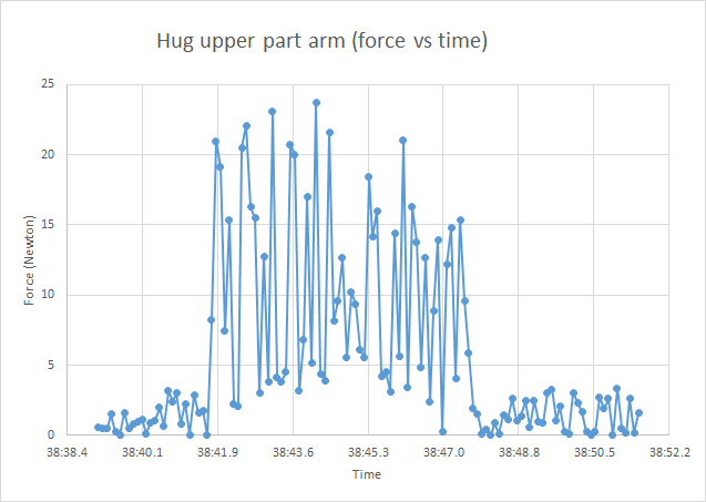 |
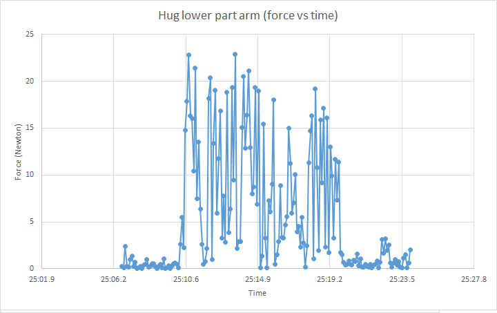 |
Simulink model
As the ROS simulation didn't give any information or feedback in respect to the acting forces, a simulink model is created. For this simulation the physical aplication has to be translated in to a mathematical model, before a controller can be designed. The model for the plant and the controller are created using Simulink.
Simplyfication and Equation of motion
When discribing a hug, the horizontal movement of the arms is more dominant than the vertical movement. Therefor we considered the move to be 2D in the x-y plane. This has the disadvantage that gravitational forces are not included in the model, and thus somewhat less accurate. Because of symmetry, it suffices to only discribe one arm. This arm will consist of an upper and a lower arm, for simplification the hands are not included in the model. When creating a mathematical model, first the free body diagram is considered.
As the robot moves both upper and lower arms independently with an independent motor, the corresponding plant consist of one arm. The plant can than be described with the balans of moments.
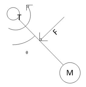
- [math]\displaystyle{ \sum M = \frac{1}{2} F_1 L_1 + T \dot{\theta_1} + K \theta_1 + M_2 = I_0 \ddot{\theta_1} }[/math]
In this formula [math]\displaystyle{ F_1 }[/math] is the force pressing on the arm at half its length [math]\displaystyle{ L_1 }[/math], [math]\displaystyle{ T }[/math] is the friction coefficient that discribes the friction in the joints, [math]\displaystyle{ K }[/math] is the stifness in the arm itself and [math]\displaystyle{ I_0 }[/math] is the inertia of the arm. The reaction moment from the upper arm working on the lower arm is added in the form of , [math]\displaystyle{ M_2 }[/math]. The inertia can be calculated because the mass [math]\displaystyle{ m_1 }[/math] and the length of the arm are known.
- [math]\displaystyle{ I_0 = m_1 L_1 ^2 }[/math]
This is discription is then implemented in simulink as shown in the figure. The values of the parameters were found in pdf.
| Parameter | Value |
|---|---|
| [math]\displaystyle{ m_1 }[/math] | 0.86 kg |
| [math]\displaystyle{ L_1 }[/math] | 0.28 m |
| [math]\displaystyle{ T }[/math] | 3 Nm/s |
| [math]\displaystyle{ K }[/math] | 1400 N |
With this a controller can be designed.
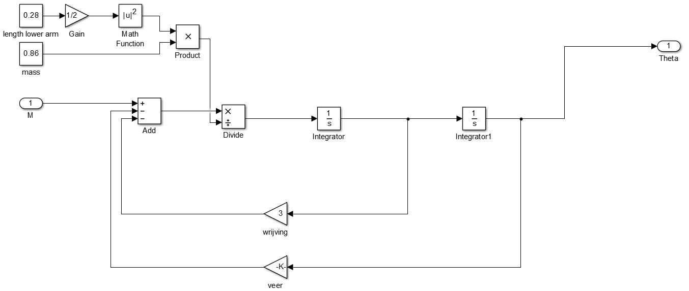 |
 |
Simulink model
From the equation of moment balans, a discription for the plant can be discribed. By applying the La Place transformation the following plant discription can be derived.
- [math]\displaystyle{ Plant=\frac{1}{I_0 s^2 + T s + K } }[/math]
In order to make the hug comfortable, some requirements are set for the hug. From the experiment we learned that the forces alternated at a high frequency and that these forces have a maximum of KIJKEN Newton. It is also necessary that the controller is stable and will not overshoot in the applied force in order to not hurt the user. As the forces are more important than the position of the arm, force control is prefered to position control.
Force feedback control was investigated, but because of its complexity and a lack of time it couldn't be implemented in the model. A position feedback control is created instead. In order to make sure the forces from the controler don't get to big, a saturation block is used, which is set at a value of 30. This is in correspondance with the experiment, where a maximum value of 30 N was found during a hug.
A PID controler [math]\displaystyle{ C }[/math] is designed to control the system.
- [math]\displaystyle{ C=\frac{K_d s^2 + K_p s + K_i }{s} }[/math]
| Parameter | Value |
|---|---|
| Kp | 1193 |
| Ki | 532.6 |
| Kd | 79.36 |
With this controler, the force output from the controler is then checked by plotting the output over the time. For this a step is used for input to mimick the user pushing against the robot arm. This step initiates at [math]\displaystyle{ t = 3 }[/math] with an end value of 25. The first peak allows for the high frequency alternation in forces, while after that the force reduces to allow the user to push the arm away if necessary.
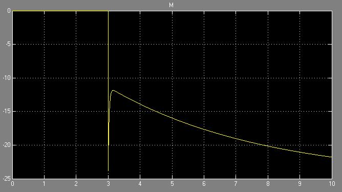
The open loop and closed loop are calculated as follows.
- [math]\displaystyle{ H=C \cdot Plant }[/math]
- [math]\displaystyle{ Closed = \frac{H}{1+H} }[/math]
With this a bode plot and a Nyquist plot are created. As the graph passes the point [math]\displaystyle{ (-1,0) }[/math] on the right side,it can be stated that the controler is stable.
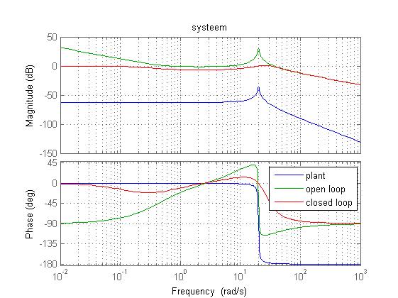 |
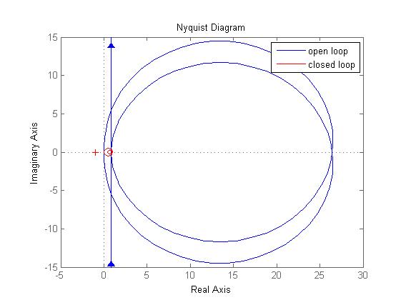 |
Discussion and Future research
For the hugging robot, AMIGO was used as a reference. AMIGO has two arms with both an upper and a lower arm. In the simulink model, however, only one part of the arm is included. This is because both parts have each their own motor and different characteristics, which means different plant. This would mean that each part would require a different controler. But using two controlers becomes increasingly complex and further prove is needed before the system can be considered stable. As a result the used simulink model is only an approximation of a hugging robot. The reaction moment from the upper arm for example is not included in this model.
To improve the model, the moment from the upper arm should be added. Numerous attempts were made to include this, but as the model could not be made stabe this was left out. Furter improvements can include a force feedback control or impedance control, in contrary to the used position feedback control. Research was done in the hope to include impedance control, but was found too complex to be implemented.
Technical Aspects
Requirements AMIGO
Exact Usage Scenario
The aim of this section is to provide an exact description of a hug that the AMIGO robot needs to perform during the final demonstration.
Assumptions
- The AMIGO robot’s shoulders are lower than the hug-receiver’s shoulders.
- The hug-sender has a clear view of the AMIGO robot and the hug-receiver without any cameras.
- The hug-sender can see what the AMIGO’s main camera sees using a display.
Hug description
- The hug-sender and the hug-receiver have already established a communication session via telephone.
- The hug-receiver turns the AMIGO robot on.
- The hug-sender turns the KINECT system on.
- The hug-sender performs several test movements: by taking several poses focused on the hug-sender’s arms and checking whether the AMIGO robot’s arms take on the same poses.
- The hug-sender spreads their arms to indicate they are ready to give the hug. The AMIGO robot also spreads its arms.
- Both the hug-sender as well as the hug-receiver are notified that a hug can now be given. This can be done for example by changing the AMIGO’s color or having it pronounce a certain message.
- The hug-receiver approaches the AMIGO robot.
- The hug-receiver begins to hug the AMIGO robot (a so-called ‘bear’-hug).
- The hug-receiver tells the hug-sender that they are ready to receive a hug from the AMIGO.
- The hug-sender makes a hugging movement by closing their arms.
- The AMIGO robot takes over after the hug-sender’s arms have reached a certain point. This is because the hug-sender cannot see the hug-receiver and the AMIGO’s arms clearly enough to give the hug-receiver a comfortable hug.
- By measuring the resistance through the AMIGO’s actuators, the AMIGO can estimate the amount of pressure being exerted on the hug-receiver. The AMIGO starts to slowly close its arms around the hug-receiver, starting with its upper arms and ending with the hands.
- (optional) By moving its arms closer together or farther apart, the hug-sender can make the AMIGO robot hug tighter or looser.
- The hug-sender or the hug-receiver indicates that they would like to end the hug.
- The AMIGO robot slowly spreads its arms outwards.
- The hug-receiver stops hugging the robot and walks away.
- The AMIGO robot and the KINECT system are turned off.
Must-Should-Could-haves
Must-have
- The AMIGO must be able to process the arm-movements of the hugging person in considerable time (ideally in real time, but probably unrealistic) and mimic them credible and reasonable fluently to the person ‘to be hugged’.
- The arms of the AMIGO must be able to embrace the person ‘to be hugged’. More specifically; the AMIGO must be able to make an embracing movement with his arms.
Should-have
- There should be a force-stop function in the AMIGO so that the person ‘to be hugged’ can stop the hug anytime if he/she desires (for example because he/she feels uncomfortable).
- The AMIGO should have a feedback function as to if and how much his arms are touching a person (pressure sensors).
Could-have
- The AMIGO could get a message from the ‘hug-giver’, the person in another place wanting to give a hug.
- The AMIGO could inform the ‘hug-receiver’ that a hug has been ‘send’ to him/her and ask if he/she wants to ‘receive’ the hug now.
- The AMIGO could receive a message from the ‘hug-giver’ that the hug has ended.
ROS
The predefined simulator of AMIGO is used for this project. This simulator runs in Robotic Operating System or ROS. ROS is programming software used for many robot projects and can not be ran in Windows (yet). Since all the work in on AMIGO in ROS is done in the control system Ubuntu 14.04, this was the control system we installed for the project.
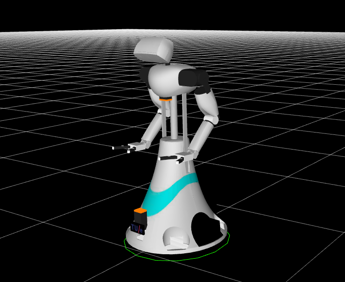
All functions for controlling the AMIGO robot in the simulator as well as its main environment are already defined and could be downloaded from GitHub. The only things we had to figure out were certain commands to move the arms and process these in a script. This can be done with some predefined operations. We used Python as a programming language and based on a template we created a script that can control the arms of amigo based on data from the Kinect. This script can be executed in the Terminal and will send orders to the simulator as long as the simulator is activated. The simulator can be started by typing the following commands in loose terminals.
-roscore, this command will activate the ROS master and the network of nodes. Without this the script and the simulator can't communicate.
-astart, this is a command that will launch a file that starts up certain parts of the AMIGO simulator.
-amiddle, this is a second command that will launch a file that starts up the rest of the AMIGO simulator and the world models.
-rviz-amigo, this will start a visualizer that shows the robot model and its environment. This can be used to see what the robot is doing.
The arm control function used for our simulation is Amigo.leftarm.default_trajectories and Amigo.rightarm.default_trajectories . These commands work as follows. In the part about AMIGO's degrees of freedom and Coordinates conversion is discussed that AMIGO has seven joints in his arms that can be rotated with a certain amount. Amigo.lefarm.default_trajectories and Amigo.leftarm.default_trajectories can be used to predefine a certain sequence of positions for the seven joints in respectively the left and right arm of the robot. The previously defined sequences of poses can be executed with the commands “Amigo.leftarm.send_joint_trajectory” and “Amigo.rightarm.send_joint_trajectory”. These commands send the sequences for the arms to the simulator and AMIGO will then move his arms in the given positions.
A ROS node is a small part of a program in ROS with a certain function. ROS nodes can communicate with each other through ROS topics. This can be compared with two mobile devices communicating with each other through a certain frequency. A node can send certain messages or instruction through a topic and another node can receive this messages and carry out the instructions.
The AMIGO simulator can be seen as a node and our script that can send the commands is a node as well that sends the commands over a topic to be received by the simulator node.
The script used will receive an array size 1x14 with 14 numbers in it from the computer housing the Kinect software, derived from Kinect data. This array will be send over the topic and the script is written in such a way that it can receive this array and process it to two 1x7 arrays that will be the coordinates of the arm joints for the two arms of AMIGO. The script in windows will continuously send a new array with numbers based on the data derived of the Kinect. This way the script will continuously receive data which it will then process and send to the simulator. This way AMIGO will continously adjust its arm poses to the poses of the person in front of the Kinect interface. More on how this works is discussed under Kinect and Connection ROS-Kinect.
Kinect
In order to imitate the hug the hug-sender is making, it is necessary to capture the movements of their body. To do so we needed some kind of motion capturing device and we chose the Kinect V2 technology from Microsoft. This technique was designed to translate poses made by humans into video games and therefore we deemed it well suited to translating someone’s arm movements into data that the AMIGO robot could use to imitate the hug. Above all we could easily access this motion sensing device as one of our group members already owned one.
This section describes how use the Kinect’s input to let the AMIGO copy the hug-sender’s arm motions.
AMIGO’s degrees of freedom
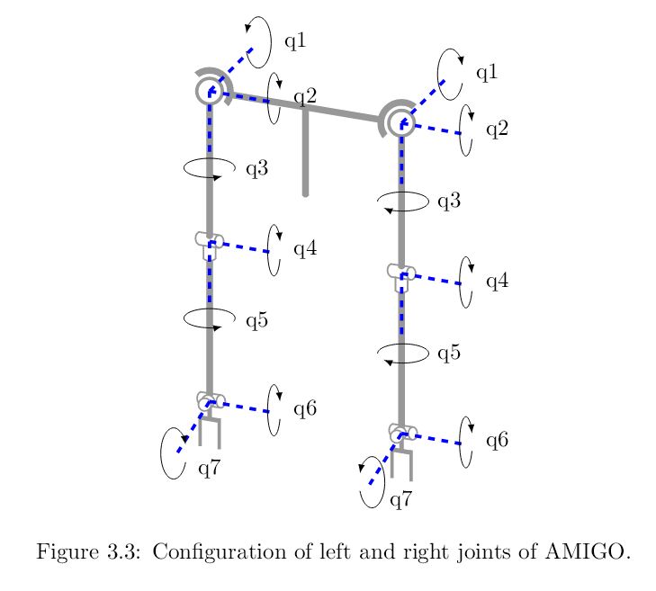
The AMIGO uses two PERA manipulators as arms that have seven degrees of freedom each. Imitating a hug with AMIGO’s arms requires that we send it the correct information it needs to copy the hug-sender’s arm poses. What follows is a short description of the motions governed by each degree of freedom for the left arm. Note that this description of the degrees of freedom of the right arm is a mirror image of this description. We used Max Baeten’s final thesis as guide to explain the different degrees of freedom.
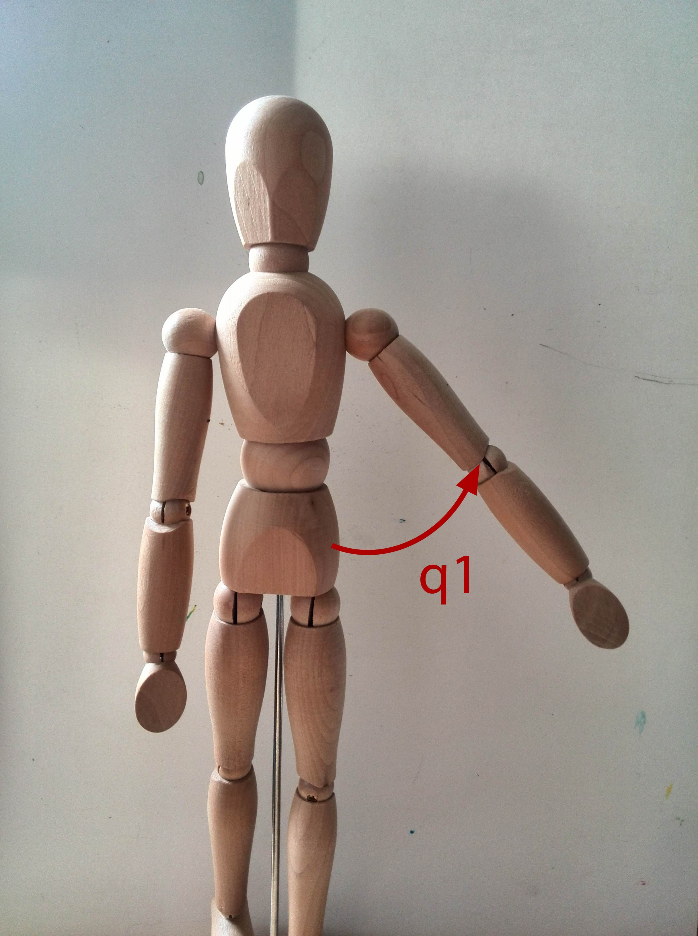 |
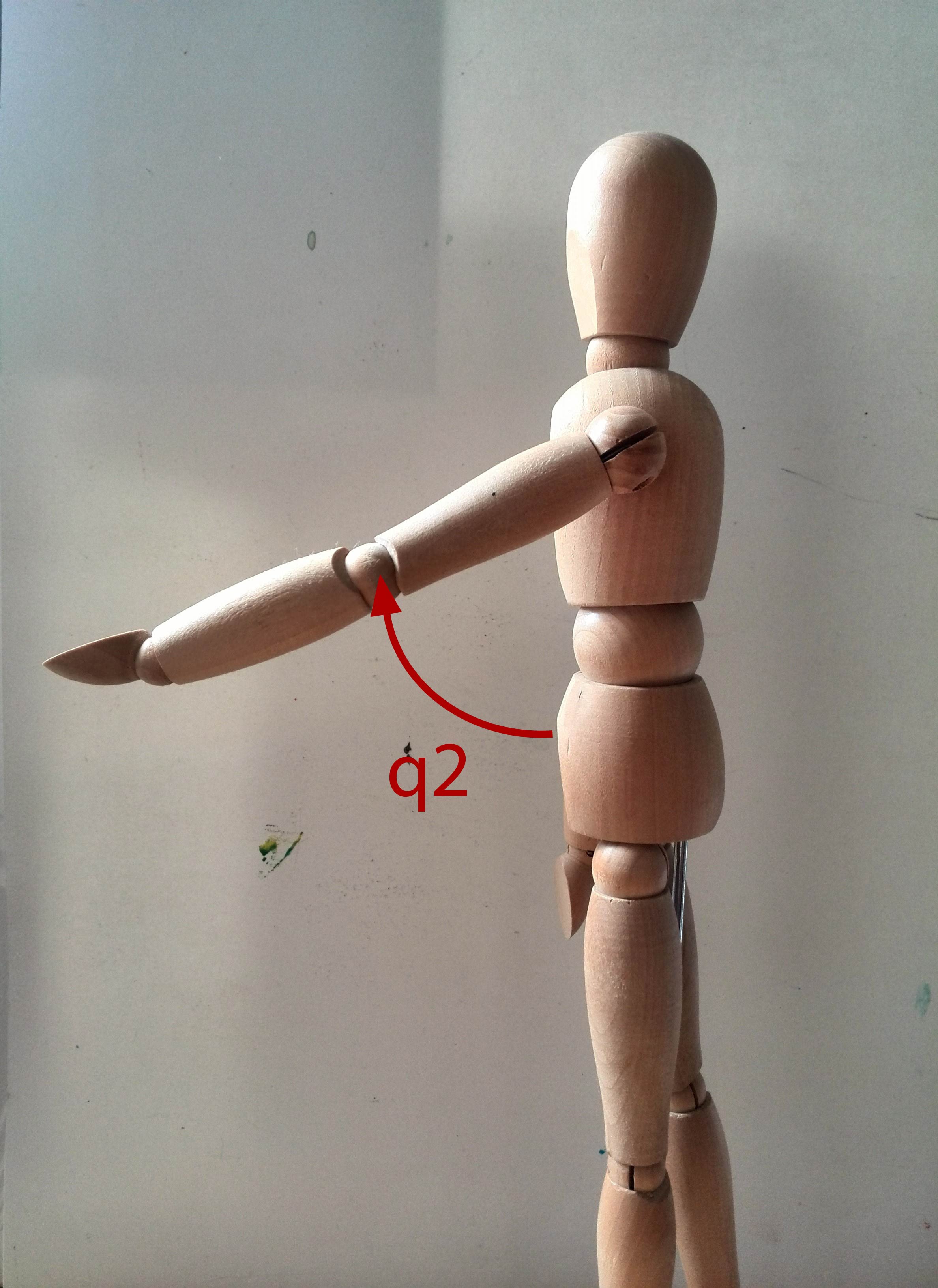 |
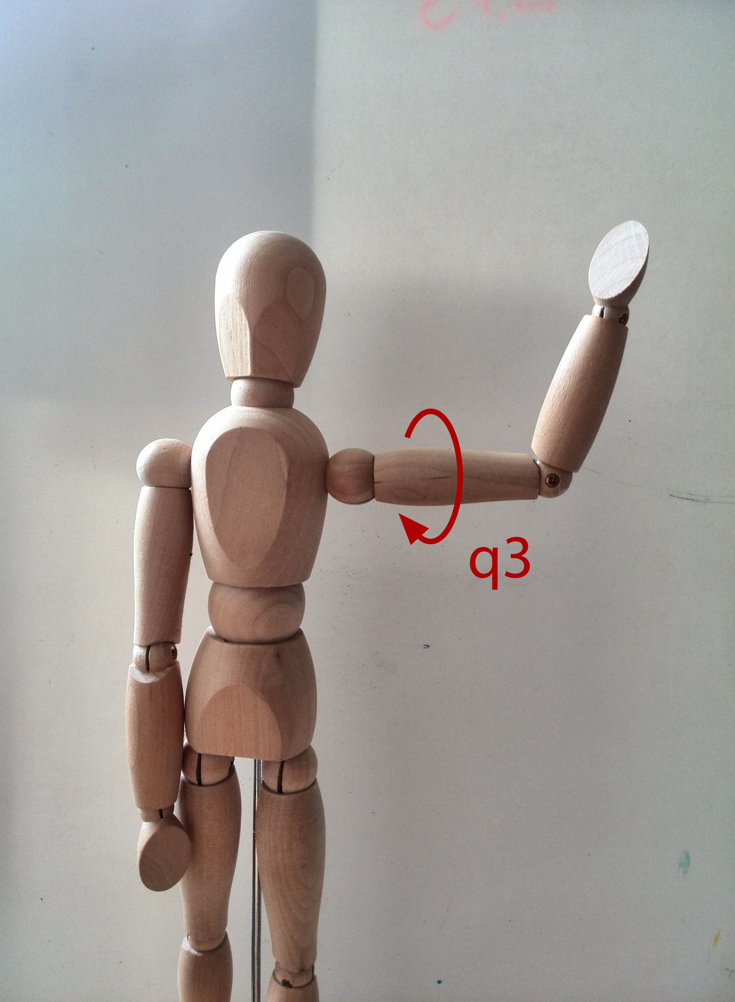 |
Q1 The first degree of freedom is the angle that determines how far the arm is raised sideways. When the arm is not raised, the angle is 0. The arm can only be raised up to the point that it is fully pointing out, it cannot be raised any higher, resulting in an upper limit of [math]\displaystyle{ 0.5 \pi }[/math]. For some reason however, the angle is given as a negative number (meaning that a fully raised arm corresponds to an angle of [math]\displaystyle{ - 0.5 \pi }[/math]).
Q2 The second degree of freedom is the angle that determines whether the arm points forwards or backwards. It should be seen as the angle between the torso of the person and the projection of the arm onto the side of the person. In combination with the first degree of freedom this angle defines the direction the upper arm is pointing in. It’s range is between [math]\displaystyle{ - 0.5 \pi }[/math] (backwards) and [math]\displaystyle{ 0.5 \pi }[/math] (forwards).
Q3 The third degree of freedom determines how much the upper arm is rotated over its own main axes, also known as its roll. It can reach from [math]\displaystyle{ -0.5 \pi }[/math] to [math]\displaystyle{ 0.5 \pi }[/math] where a positive value represents an inward rotation and a negative value represents an outward rotation. This rotation partially determines the direction the lower arm points towards when the elbow is bent.
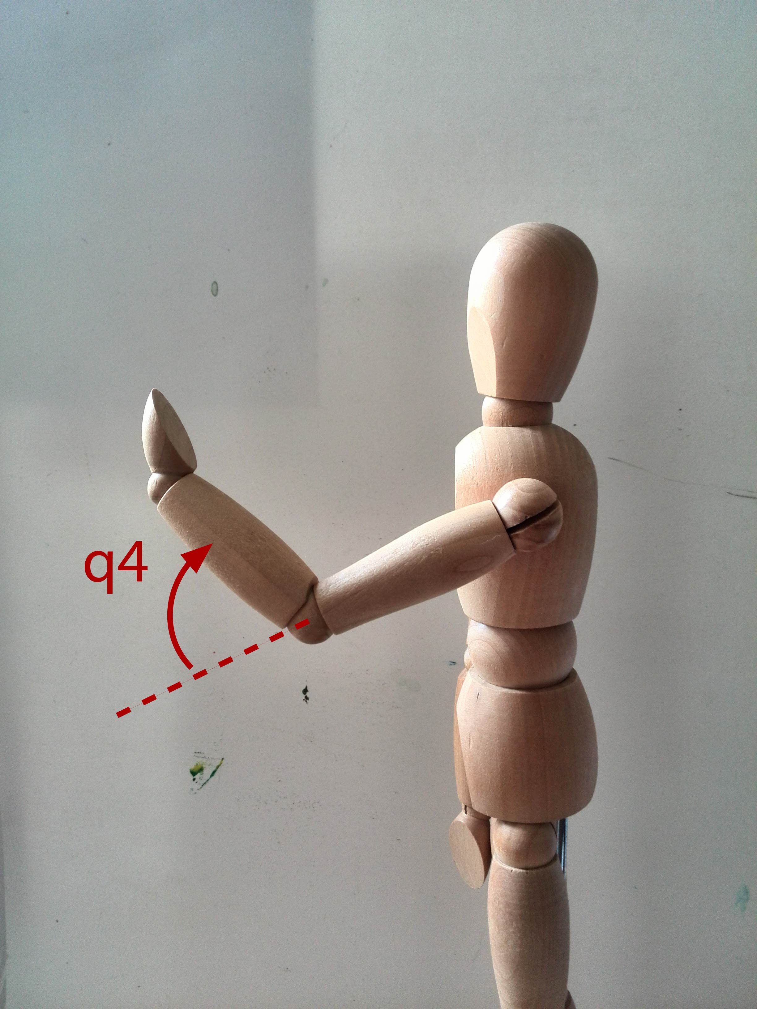 |
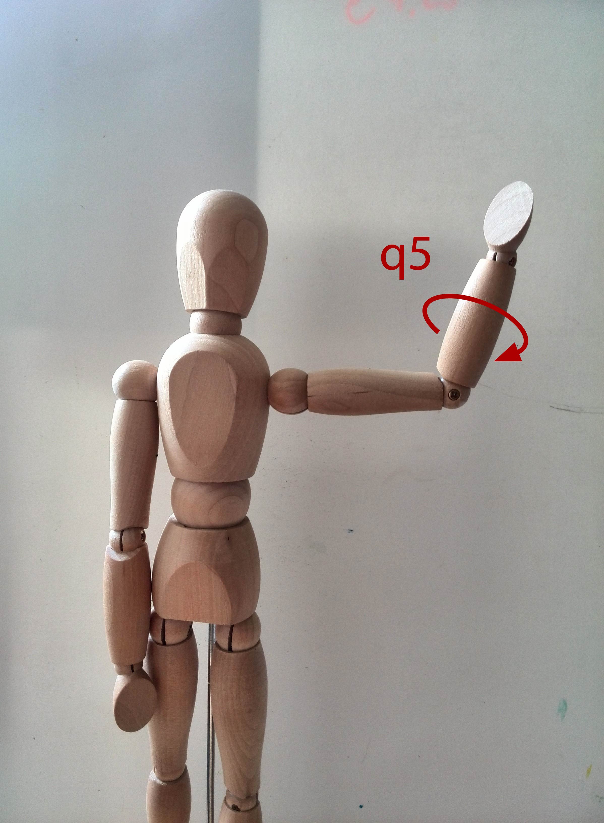 |
 |
 |
Q4 The fourth degree of freedom concerns the angle at which the elbow is bent. An angle of 0 corresponds to a fully stretched arm whereas an angle of 2.23 corresponds to the maximum angle at which the AMIGO’s elbow can be bent.
Q5 The fifth degree of freedom is comparable to the third, though it represents the roll of the lower arm. It can vary from -1.83 to 1.83 with a positive angle indicating that the lower arm is rotated inwards. It partially controls the direction the hand is pointing towards.
Q6 The sixth degree of freedom determines the angle at which the wrist is bend in the direction of the palm of the hand. It ranges from -0.95 to 0.95. An angle of 0 corresponds to a stretched wrist and a positive angle means that the hand is bent in the direction of the palm.
Q7 The seventh and final degree of freedom controls the angle the hand is rotated about the direction the hand’s palm is facing. It is best described as trying to make a waving motion sideways whilst not moving the lower or upper arm. It varies from -0.61 to 0.61 where an angle of zero represents no rotation. A positive angle corresponds to an anti-clockwise rotation when looking at the palm of the (left) hand.
Extracting data from the Kinect sensor
The SDK of Kinect comes with predefined functionality to retrieve information about the ‘skeleton’ of the users the Kinect is tracking. These skeletons are representations of the position and orientaton of the user’s joints e.g. shoulders and knees. Several examples of code are provided by Microsoft and can be downloaded together with the SDK. We used the position of these joints in camera space to calculate the angles needed to emulate the hug-sender’s arms in the AMIGO. Below it is explained how each of these angles were calculated for the left arm. The c++ code used to do this can be found here. Note that because c++ does come with a standard library for vectors and vector manipulation we needed to define our own vector class and several standard vector operations. Finally, in the code a lot of vectors are named using the following convention: the first two letters of the joint it is pointing from, the number 2 as the word ‘to’ and the first two letters of the joint is pointing towards.
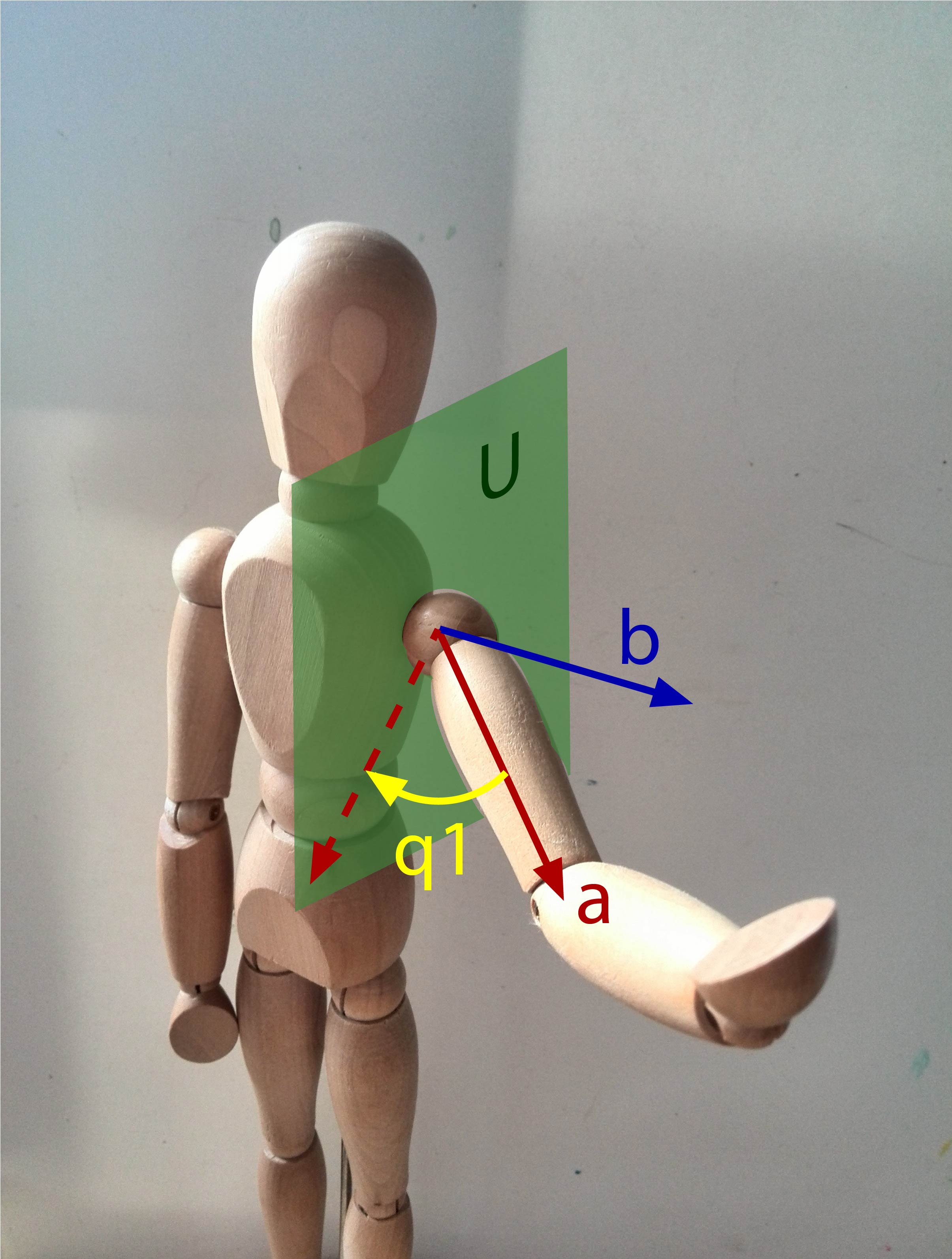 |
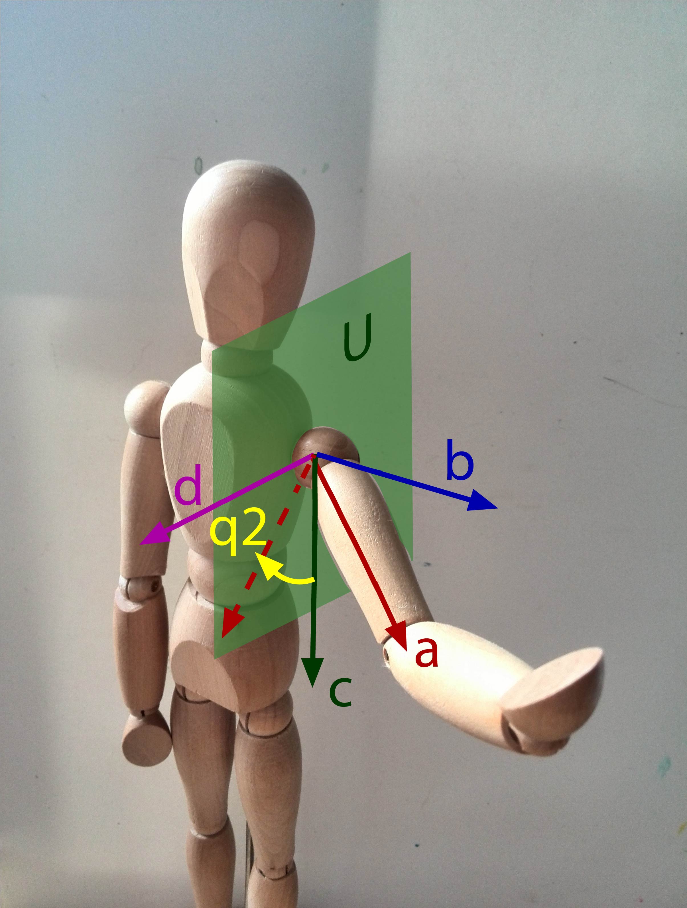 |
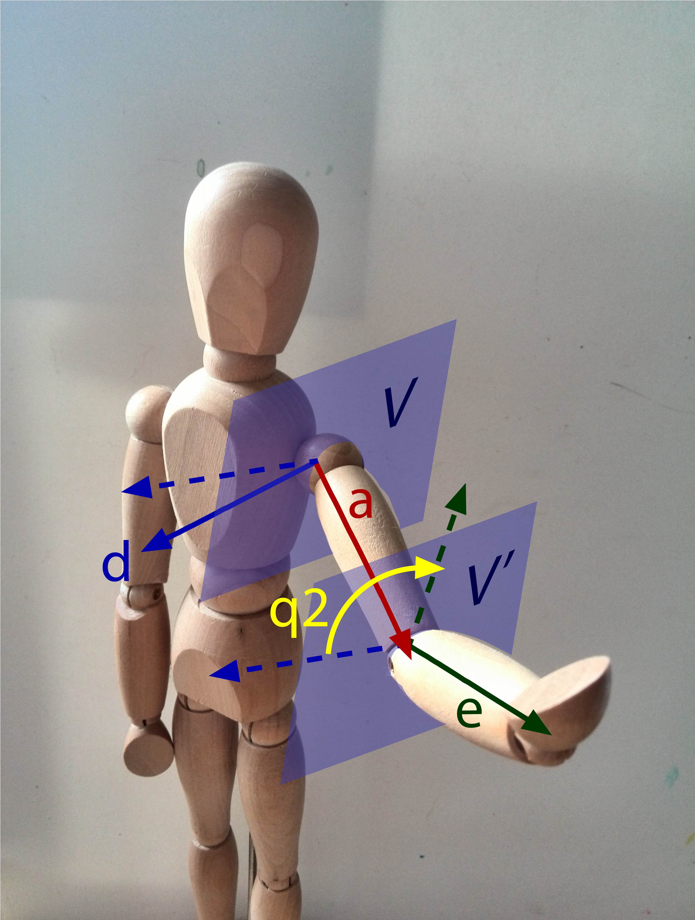 |
Q1 Let [math]\displaystyle{ \boldsymbol{a} }[/math] be the vector pointing from the shoulder to the elbow and let [math]\displaystyle{ \boldsymbol{b} }[/math] be the vector pointing to the left of the person (this can be calculated by taking the difference between the position of the left and right shoulder). Let [math]\displaystyle{ U }[/math] be a plane perpendicular to [math]\displaystyle{ \boldsymbol{b} }[/math], this represents the side of the person. The first angle is equal to the angle between [math]\displaystyle{ \boldsymbol{a} }[/math] and its projection [math]\displaystyle{ \mathcal{P}_U(\boldsymbol{a}) }[/math]. Because of the strange decision to let the angle be given in a negative number, it should be multiplied by -1.
Q2 Let [math]\displaystyle{ \boldsymbol{c} }[/math] be the vector pointing down the left side of the body. Let [math]\displaystyle{ \boldsymbol{d} }[/math] be the vector pointing forwards from the left shoulder, [math]\displaystyle{ \boldsymbol{d} = \boldsymbol{c} \times \boldsymbol{a} }[/math]. The second angle is then equal to the angle between the projection [math]\displaystyle{ \mathcal{P}_U(\boldsymbol{a}) }[/math] and [math]\displaystyle{ \boldsymbol{c} }[/math]. To determine whether the angle should be positive or negative, take the dot product between [math]\displaystyle{ \boldsymbol{a} }[/math] and [math]\displaystyle{ \boldsymbol{d} }[/math]. The sign of the angle is equal to the sign of this dot product.
Q3 The third angle is a bit more difficult to determine. Let [math]\displaystyle{ \boldsymbol{e} }[/math] be the vector pointing from the elbow to the wrist. Let [math]\displaystyle{ V }[/math] a plane perpendicular to the vector [math]\displaystyle{ \boldsymbol{a} }[/math]. The third angle is equal to the angle between the projections [math]\displaystyle{ \mathcal{P}_V(\boldsymbol{d}) }[/math] and [math]\displaystyle{ \mathcal{P}_V(\boldsymbol{d}) }[/math]. To determine the sign of the angle it is necessary to define another vector. Let [math]\displaystyle{ \boldsymbol{f} }[/math] be the cross product between the two projections, [math]\displaystyle{ \boldsymbol{f} = \mathcal{P}_V(\boldsymbol{d}) \times \mathcal{P}_V(\boldsymbol{e}) }[/math]. [math]\displaystyle{ \boldsymbol{f} }[/math] points in the same direction as [math]\displaystyle{ \boldsymbol{a} }[/math] when the rotation is positive and in the opposite direction when it is negative. This means that the sign of the angle is the same as the sign of the dot product of [math]\displaystyle{ \boldsymbol{a} }[/math] and [math]\displaystyle{ \boldsymbol{f} }[/math].
Q4 The fourth angle simply is the angle between the vectors [math]\displaystyle{ \boldsymbol{a} }[/math] and [math]\displaystyle{ \boldsymbol{e} }[/math].
Q5 The fifth angle can be calculated in a similar way as the third angle. Let [math]\displaystyle{ \boldsymbol{g} }[/math] be the vector pointing from the wrist to the tip of the hand. Furthermore, let [math]\displaystyle{ W }[/math] be a plane perpendicular to [math]\displaystyle{ \boldsymbol{e} }[/math]. The angle is equal to the angle between the projections of [math]\displaystyle{ -\boldsymbol{a} }[/math]and [math]\displaystyle{ \boldsymbol{g} }[/math] on [math]\displaystyle{ W }[/math]. To determine the sign we take the cross product [math]\displaystyle{ \boldsymbol{h} = \mathcal{P}_W(-\boldsymbol{a}) \times \mathcal{P}_W(\boldsymbol{g}) }[/math]. The sign of the angle is equal to the sign of the dot product between [math]\displaystyle{ \boldsymbol{e} }[/math] and [math]\displaystyle{ \boldsymbol{h} }[/math].
Q6 The sixth angle is calculated similarly as the fourth angle. It is equal to the angle between the vectors [math]\displaystyle{ \boldsymbol{e} }[/math] and [math]\displaystyle{ \boldsymbol{g} }[/math]. It should be noted that the sign of the angles should be determined, but we had forgotten to do so.
Q7 Some attempts were made to determine the seventh angle, but we did not succeed in this. We are of the impression that this does not have any major consequences for the hug however. It is a very specialized, local motion whereas a hug is performed using the entire arm. Secondly, the motion can be recreated by changing the upper arm’s roll.
Connection between ROS and Kinect
Sending data to ROS
The SDK for Kinect we used to calculate the angles of the hug-sender’s arms runs on a Windows machine whilst the AMIGO’s software runs on Ubuntu 14.04. These two operating systems are not easily combined. There are several solutions to this problem:
- We can run the Ubuntu system in a virtual machine on the Windows machine. We chose not to pursue this option as we did not have any experience which such a construction and because we feared that it would decrease the system’s performance.
- There are several drivers and libraries to make the Kinect run on an Ubuntu machine. An example of these is Kinect Fusion. However, this particular library is not well suited to capturing dynamic human poses. It was made to be able to navigate static environments. We looked at other libraries such as OpenNI, but we decided that it would be easier to just use the official Microsoft libraries on a Windows machine. A major influence on this decision was the fact that we had already found another solution, which brings us to the next solution.
- We can send data from the Windows machine to the Ubuntu machine over a network. The rosserial windows package for ROS deals with the complicated network stuff (e.g. sockets) and lets the user publish ROS messages on a ROS topic on the Ubuntu machine. This solution also fits our conceptual technique better. The point of our hugging robot is that the hug-sender and hug-receiver can hug each other whilst being separated by a large distance.
By having a Windows application publish the angles calculated as a single message onto a ROS topic, we can create a ROS node that subscribes to this topic and uses the angles calculated to operate the arms. To use this code, a rosserial socket node needs to be run on the Ubuntu machine for it to be able to receive messages via a network. This is explained in more detail in the rosserial tutorial
Sending data between Windows applications
Two different applications are used to take input from the Kinect sensor and manipulate its data into the angles that control the AMIGO’s arms and to send the data to the Ubuntu machine. It would not be desirable to have such a construction in the final product, but we faced some compatibility issues merging the two applications. Instead we used a sloppy method to transfer data from the first application to the second. The first application writes to a text-file and the second one reads from the same text-file. We had tried to use pipelines to send data, but we lacked proper knowledge of c++ to get it to work.
scripts
These are links to separate pages explaining the different scripts created to make the prototype work.
- Calculating the angles from the
Jointdata structure. - Sending the data between Windows applications.
- Sending the data to the Ubuntu machine.
- Using the data to control the AMIGO’s arms.
A download link of all the different projects can be found here.
Evaluation
During the project of designing our hugging robot and creating a potential prototype we had a lot of things where we learned from and would do differently if we had to do it over. The first thing was that we focused too much on getting amigo to work. We were all new with using robots in general and therefore we were really enthusiastic that there was a possibility of using the amigo robot. Due to this tunnel vision we forgot one of the most important if not the most important factor of a hug: the continuous amount of forces that get applied on the bodies during a hug. We were so caught up in getting the motion and position right using Kinect, that we forgot about the forces and did not see its importance until late in the project. Therefor we did the force experiment and created the Simulink model too late into the project and on top of it, we figured that the simulator that we were running did not support forces. This could all have been prevented if we made a sketch of the hug that we wanted to give and of what was happening during a hug. Another thing that could have done better was the efficiency of the way we installed Ubuntu and the ROS simulator. We had as Mr. Molengraft said “two horses running on the same path”, both trying to figure out how to install ROS individually. With better communication and planning, this could have gone a lot smoother, where one team member could figure out how to install it and then explain it to the others. Where the other members could have done something different in the meantime.
One of the things that we are really proud of is the fact that we wanted to get Kinect working in combination with amigo’s software from the beginning of the project and that we indeed got that working. It might even be usable for amigo in the future or NAO.
Starting this project, we all had no experience of what to do with such a big project without a guiding hand of the university, and I can safely say that it was a great experience for us all and that we truly learned something.
Interesting Links
Some interesting links and other sources for anyone interested in copying a users movements with Kinect, hugs or shadow robotics.
https://www.youtube.com/watch?v=KnwN1cGE5Ug
https://www.youtube.com/watch?v=AZPBhhjiUfQ
http://kelvinelectronicprojects.blogspot.nl/2013/08/kinect-driven-arduino-powered-hand.html
http://www.intorobotics.com/7-tutorials-start-working-kinect-arduino/
Anand B, Harishankar S Hariskrishna T.V. Vignesh U. Sivraj P. Digital human action copying robot 2013
http://singularityhub.com/2010/12/20/robot-hand-copies-your-movements-mimics-your-gestures-video/
http://www.telegraph.co.uk/news/1559760/Dancing-robot-copies-human-moves.html
http://www.emeraldinsight.com/doi/abs/10.1108/01439910310457715
http://www.shadowrobot.com/downloads/dextrous_hand_final.pdf