Embedded Motion Control 2016 Group 1: Difference between revisions
No edit summary |
|||
| (48 intermediate revisions by 3 users not shown) | |||
| Line 198: | Line 198: | ||
|} | |} | ||
== Approach of the corridor == | |||
The code for the corridor challenge took advantage of the simplicity of this challenge. The robot moved forward in the initial straight corridor. The distance to both sides has been measured with the laser scanner in order to center the robot in lateral direction. If the distance to the right was larger the robot would move left and vice versa. A bundle of measurement points was used to avoid strong reactions to disturbances. Furthermore, if the distance was too great the robot would not react, this was aimed to avoid a strong reaction to gaps in the wall. This method was robust enough for this situation in which PICO would be approximately aligned with the corridor from the start. Thus, no advanced and more difficult code was used. In the meantime the environment was scanned for an exit, if such an exit was wide enough the applicable code was used to turn PICO. | |||
First, the robot was directed to the center of the junction; this was based on odometry and the known width and location of the exit. Then odometry was used to rotate the robot 90 degrees in the direction of the exit. A potential field code was then used to move the PICO forward and into the exit. The potential field was aimed to correct for any inaccuracy in the odometry. A target that was always exactly in front of PICO at all times has been used for this. Once the walls on the side were sufficiently close PICO considered itself in the exit and used the initial alignment tactic to drive to the end of the corridor. These steps have been visualized in Fig.3. | |||
{| | |||
|[[File: Corridor.jpg|thumb|right|500px|Fig.3 Corridor strategy in 4 steps]] | |||
|} | |||
== Analysis and learned lessons == | == Analysis and learned lessons == | ||
The PICO robot | During the corridor challenge two attempts have been used. It was found that during the first attempt the potential field pushed PICO out of alignment and made is scrape the wall at the exit. The wall on the right side was scraped, which caused the distance to the wall on the left side to be too big for the alignment code to work. This was due to the gap neglecting tactic. A combination of two additional pieces of code that were aimed to increase robustness (odometry correction and gap neglecting) thus caused PICO to not function optimally. | ||
During the second attempt the potential field managed to keep the robot away from the wall. The alignment code then functioned correctly and PICO crossed the line in 17.5 seconds which was sufficient for a third place. | |||
One improvement to this code was adjusting the code for the corridor, changing the threshold of distance at which it won’t react. In order to coop with open spaces the code has eventually been changed to a wall following code in combination with potential field. More information regarding this new code can be found further in this wiki page. Another change has been made regarding target placement and tracking with the potential field. This avoided future problems with using the potential field to reach targets. | |||
= '''Geometry detection''' = | |||
Along with the “movement” capabilities of the robot, detecting and interpreting the environment accurately is one of the most important low level tasks. This especially becomes important considering our approach to solve the maze since we need to list all the possible directions that the robot can go for the decision making. By this way, the robot is always making ‘aware’ movements, considering all the options and moving based on the interpreted environment and the decided direction instead of merely being directed by the potential field to move towards the most obvious gap in the maze. | |||
Considering the perpendicular structure of the maze, we listed all possible geometries that can be encountered in the maze that either requires a decision making or a turn to be taken. These are: | |||
Straight-Right Junction, Straight-Left Junction, Right Corner, Left Corner, 4-way junction, T-junction, dead-end and a door. These geometries are scanned at each iteration of the loop unless PICO is still moving towards a target. | |||
Note that stopping movement of the robot is taken as soon as an environment is detected in order to minimize the drifting from the last known point. | |||
For further and more elaborate description on how these junctions are detected visit the following sub-page: | |||
[[Embedded_Motion_Control_2016_Group_1/Geometry Detection|Geometry Detection]] | |||
= '''Potential field''' = | |||
== General idea == | |||
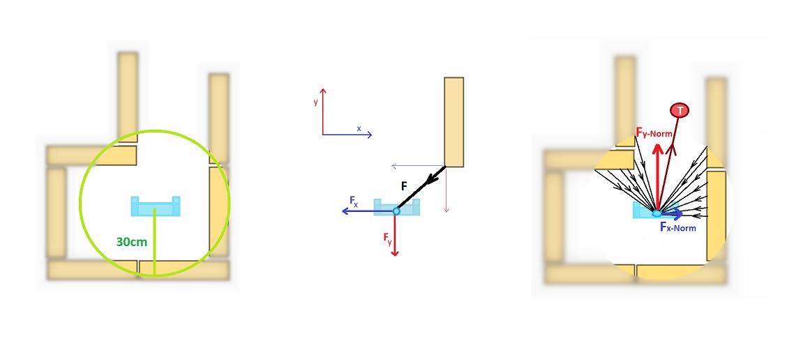
For the ease of implementation, a straight forward potential field algorithm is used. The robot is “pushed away” by the walls in the proximity and “attracted” by the target points decided based on the decision making strategy. To provide a smooth movement for the robot, only the walls within 30 cm radius of the robot is taken into consideration when forming the resultant force vectors on the robot. Each wall point in the relevant radius of the robot pushes the robot inversely proportional to its distance to the robot. These forces are decomposed into x and y components in order to define the angle of the repulsive force, so that the robot can move towards the opposite direction of the resulting repulsive force. Target force of the robot is also normalized, based on the x and y direction of the target with respect to the robot. A snippet of the code used for the potential field can be found with the link at the bottom of this wiki page. | |||
[[File:PotentialField.jpg|thumb|center|700px|Fig. 4 Potential field]] | |||
== Use of target == | |||
The movement through the maze is done by placing targets inside the junctions that are detected, which will act as attracting forces for the PICO. With this it is ensured that the PICO will make the necessary turns. When no junction is detected, the target is placed one meter ahead of PICO, which makes it go straight. | |||
Two possibilities of the target placement were considered when a junction is detected and PICO needs to turn in a corner. In one of the methods the target is first set in the middle of the junction which will just make the robot move straight. After the target is reached, PICO starts to rotate in the desired direction. When the rotation is finished new target is placed inside the junction and with that PICO successfully drives into the corner. Taking that the width of the junction is known, a line from the junction with similar width is searched for. When such a line is found, the target is then placed in the middle of this line. The other method is when the target is set directly inside the junction. With this target placement PICO will directly steer inside the junction and the cornering will be smoother. Both methods are shown in Fig. 5. | |||
[[File:Target.jpg|thumb|right|400px|Fig. 5 Methods of target placement]] | |||
The first method was thought to be less robust because a misalignment on a junction or intersection may force the robot to go in an undesired direction. Another advantage to the second method of directly placing the target inside the junction was that it is more robust when there are two corners close to each other. Therefore, the choice for the movement of PICO was conducted with the direct method of target placement. A necessity for these methods of movement is keeping track of the target. When a geometry is detected relative targets are placed. These targets are then checked by the pledge algorithm and adequate movement determined, meaning there is only one target left. This target needs to then be transformed into a global target which is used for setting a definitive relative target and direction of movement. The movement is realized using the potential field and the target is updated in this mentioned loop. The transformation of the target from relative to global and vice versa is shown by these transformation matrices. | |||
[[File:GlobalTargetFormula.jpg|left|600px]] | |||
[[File:RelativeTargetFormula.jpg|left|600px]] | |||
Where x,y are the x and y odometry position and α is the odometry angle. | |||
= '''Pledge algorithm''' = | |||
The Pledge algorithm is a modified version of the wall following algorithm such that it prevents getting stuck into loops. It’s guaranteed to reach an exit of any 2D maze from any point in the middle, without needing to mark or remember the path it takes. The Pledge algorithm has the following composition [1]. The robot starts by picking a direction and always moving in that direction when possible. When a wall is encountered, the robot should start wall following and count the number of turns it makes (e.g. right turn is -1, left turn is 1). The wall following is stopped when the total number of turns that the robot has made is zero (i.e. the counter is zero) and then move in the initially picked direction. The counting ensures that the robot won’t get stuck in a loop or a G shaped geometry and that eventually the exit will be found. The Pledge can however make the robot visit paths that have already been passed, although the counter will have a different value. For a more convenient way of keeping track of the counter, all situations that PICO might encounter are examined; as shown in Fig. 6. With this knowledge the counter value would be known for each situation and can easily be implemented in the appropriate code. A snippet of the code can be found at the bottom of this wiki page. | |||
[[File:JunctionsGroup1.jpg|thumb|right|800px|Fig.6 Movement in different junctions]][[File:MazeChallengeGroup1.jpg|thumb|center|800px|Fig.7 Pledge algorithm and open-space strategy for the actual maze]] | |||
The simplicity of the algorithm and the fact that it ensures that PICO can exit the maze makes the Pledge algorithm suitable for the maze challenge. In Fig. 7 the maze that was used in the challenge is taken as an example to visually present the way this algorithm works. | |||
Taken that the movement of the robot is done by placing targets and driving using potential field, the Pledge algorithm is strongly dependent on geometry detection. This can be a crucial disadvantage, because wrongly detected geometry may steer the robot in an undesired direction and with that making the counter value incorrect. | |||
Due to the advantages that it brings, mainly with its simplicity, this algorithm is used for solving the maze challenge. The Pledge algorithm drew interest from other groups after the final presentation and was also implemented as their algorithm to solve the maze. | |||
= '''Structure of code''' = | |||
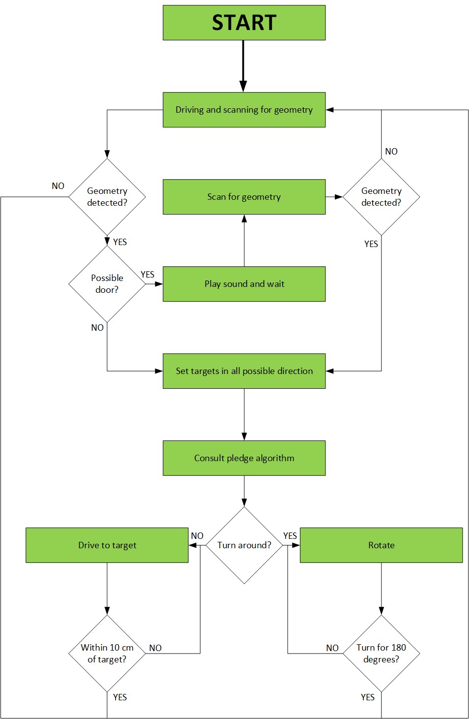
[[File: StructureGroup1-2016.jpg|thumb|right|450px|Fig.8 Flow diagram of the code structure]] | |||
The structure of the code has been centered around the pledge algorithm for maze solving. A single threaded code with a refresh frequency of 10 Hertz has been used. This frequency was considered adequately high in order not to require multithreading. As cautionary procedure a second code with a lower movement speed of the PICO robot has been made. A snippet of the main code can be found at the bottom of this wiki page. | |||
Fig.8 shows the topology of the code. Initially the robot is moving and scanning for geometry. The potential field is preventing the robot to crash while moving and the wall following may be deployed in order to move in the correct direction in open spaces. If geometry is detected, such as crossings or dead ends, the code will determine whether the robot will attempt to open a door or make a decision on where to move. After attempting to open a door the robot will scan for geometry again after waiting for 5 seconds. This way it will detect whether a door has been opened and where it can move. The picture shows that the robot may not detect geometry after trying to open the door; this may seem strange but considers the situation in which the door in a dead end opens and there is a normal corridor ahead. Once a geometry has been detected all possible directions are marked with a target. | |||
The pledge algorithm is then used to decide which direction PICO should move towards. This can either be done by selecting one of the targets and using the potential field algorithm to move towards that target, or move 180 degrees based on odometry. Movement towards a target is stopped when the robot is within ten centimeters of the target. Rotation is stopped when the difference in angle according to odometry is 180 degrees. | |||
This strategy is performed using a single threaded while loop; flags are used to keep track on what are the next steps required to travel through the maze. This furthermore ensures that a movement command is only send to the holonomic base once every iteration. This prevents an overflow of commands which can cause PICO to not react to new commands. Furthermore, flags are used to ensure that PICO will not infinitely check for a door when it encounters a potential door. | |||
= '''Open spaces''' = | |||
When an open-space is detected PICO finds the closest wall to its right and starts following it. The strategy that is used for the wall following is to maintain a set distance to a wall using a series of range measurements [2]. When a distance to the nearest obstacle is measured, it is possible to follow the surface by just moving in such a fashion that the smallest distance to a wall is perpendicular to the movement direction [2] . This allows for PICO to also take turns just with this algorithm. The open-space movement is illustrated in Fig.7. The wall following algorithm is a simple and efficient method for movement in open-spaces that worked sufficiently in the simulations and in the real maze and testing, which are the reasons why it was implemented in our strategy. Implementation of this in the code can be found in the code snippet for potential field at the bottom of this page. | |||
= '''Uniqueness''' = | |||
The most unique aspect of our code was the pledge algorithm. This simple but elegant solution was chosen to be able to finish the coding in the given amount of time. This algorithm is able to get out of any maze without requiring any form of mapping. The preconditions are that you start inside of the maze and finish outside; furthermore the direction of the robot must be known. These preconditions fit the context of the maze challenge, making this an ideal solution. The time saved by choosing this algorithm was used for optimization of robustness of the code. | |||
Another uniqueness of our code is the coordination/communication between the decision making (pledge), movement (target setting and movement towards the target) and the detection (from low level edge detection to higher level geometry identification). | |||
= '''Maze challenge''' = | |||
On 8th of June the [[Embedded Motion Control #Maze Competition]] was conducted. Unfortunately our group didn't succeeded in completing the challenge in both attempts. The videos of both attempts can be viewed by clicking on the pictures below. | |||
{| | |||
|[[File:EMC_MazeChallenge_Att1.jpg|left|250px|link=https://www.youtube.com/watch?v=G3x4LAWFy3Q]] | |||
|[[File:EMC_MazeChallenge_Att2.jpg|right|250px|link=https://www.youtube.com/watch?v=ZM7T5luQ3zg]] | |||
|} | |||
== Problems == | |||
=== First attempt === | |||
The first problem encountered in the maze challenge was with an unfamiliar geometry. Primarily the exit on the right was recognized with no exit to the left; this geometry was thus recognized as a T-junction. The recognition as T-junction caused the target to be placed straight ahead of the robot, this caused PICO to place its target inside of a wall; this can be seen in the picture. The robot would thus approach the wall head-on. In the first try the potential field was not quick enough in reacting to the approaching wall and thus PICO had a collision. | |||
{| | |||
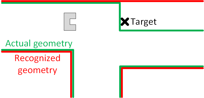
|[[File: MazeProblem-gr1-2016-1.png|thumb|right|750px|Fig.9 The right corner that was recognised as a junction]] | |||
|} | |||
=== Second attempt === | |||
In the second attempt the movement speed of PICO was lowered. Due to the fixed frequency of the coding loop PICO checked for possible collisions more frequently with respect to distance. The potential field was thus able to avoid hitting the wall at the first intersection. However, this still caused problems for PICO to reach its target as it was inside of the wall. Moving the wall luckily helped PICO to continue its attempt. | |||
In the description of the maze challenge, the depth of the door was defined as approximately 30 cm. Based on this, valid depth of the door was defined in the ranges of 25-35 centimeters. However, in the actual maze challenge door depth was 40 cm, which is why it was failed to be detected. | |||
After missing the door PICO was strongly misaligned with the maze. This was due to the wall following and the unrecognized door. The misalignment caused PICO to put the target at the right relative to the distance ahead of it and its own pose with respect to the corner. The target thus once more ended up in the wall. As with the false T-junction this may be improved by detecting whether targets are not blocked when setting them. Furthermore, additional code may be implemented that recognizes a repetition of movements to ensure that PICO will stop attempting to reach this unreachable target. | |||
{| | |||
|[[File: MazeProblem-gr1-2016-2.png|thumb|right|750px|Fig.10 The misalignment problem with a target set.]] | |||
|} | |||
The target set overall was not robust enough and the geometries encountered in the maze were not encountered during testing or simulation. Perhaps, more serious thought into how to find situations in which the code may not be applicable could’ve prevented this. | |||
== Successes == | |||
*The first 3 geometries that the robot has encountered (2 T-junctions and a right corner) before the crash was identified correctly, since the robot navigated according to the pledge up until that point. | |||
*With the altered movement speed the potential field algorithm did function correctly. It avoided crashes and was able to navigate PICO to a target (if reachable). | |||
*The Pledge algorithm itself was a success and if the other issues weren’t there PICO would have solved the maze. To reassure ourselves that the algorithm works, after the challenge we ran a short test where the door would be open and PICO would start from a dead-end. This can be seen in the video below, where PICO indeed found the exit with use of this algorithm. | |||
[[File:EMC_MazeChallenge_Att3.jpg|center|250px|link=https://www.youtube.com/watch?v=HF_aBKb6POo]] | |||
*The wall following code to coop with the open spaces was also successful. The third attempt after the challenge showed that PICO was able to follow the wall at open space. This helped with eventually successfully executing the pledge algorithm. | |||
*Working code in the simulator as shown in the video below, where PICO successfully finds an exit from the maze. | |||
[[File:EMC_MazeChallenge_Simulation.jpg|center|350px|link=https://www.youtube.com/watch?v=HOeVZwPsNWE]] | |||
= '''Conclusion and recommendation''' = | |||
*The Pledge algorithm is a simple method that allows the robot to exit any maze. Only thing that has to be taken into account with this method is to have a robust geometry detection and movement. | |||
*A top level crash avoidance and feasible target setting can be implemented. | |||
*Awareness of the inter-loop behavior of the robot in the actual maze is highly important. When a movement or geometry update is being made, it needs to be made sure that the robot do not miss any other geometries or drive towards an infeasible target until the next update comes. | |||
*A great deal of resources from previous years can be found on the wiki. Being aware of the challenges and possible problems that can be encountered is crucial. But in the end, implementing ideas in your own way is also very important. | |||
= '''Learning experiences''' = | |||
*Great hands-on experience | |||
*Time and task management is crucial for this course | |||
*Programming in C++; we had limited experience with this beforehand, but are now comfortable with the coding. | |||
*You will fail lots of times. Don’t get discouraged by it | |||
*No matter how good the robot moves and reacts in the simulator, the reality will be different. Therefore, make the code as robust as possible and use every test session that you can | |||
*Use the help of the tutor as much as you can. We feel that this is something we could have improved on | |||
*Have fun and enjoy | |||
= '''Sources''' = | |||
[1] Tom Kamphans and Elmar Langetepe- "The Pledge Algorithm Reconsidered under Errors in Sensors and Motion" | |||
[2] Teruko Yata, Lindsay Kleeman and Shin'ichi Yuta- "Wall Following Using Angle Information Measured by a Single Ultrasonic Transducer" | |||
= '''Code snipets''' = | |||
*Main loop | |||
https://gist.github.com/anonymous/86b23a489a7c83c4de0dcc80496286a7 | |||
*Pledge algorithm | |||
https://gist.github.com/anonymous/64bcac4471d6c4aa7c820301496911a2 | |||
*Potential field | |||
https://gist.github.com/anonymous/b5ed5f7e94dd17eabca70eb1b48a618d | |||
= '''Files''' = | |||
*Design Architecture Document | |||
[[File:Design Architecture Group 1.pdf]] | |||
*First Presentation | |||
[[File:first presentation.pdf]] | |||
*Final Presentation | |||
[[File:Final presentation.pdf]] | |||
Latest revision as of 22:32, 17 June 2016
Group Members
| 0878154 | Wouter Scholte | w dot j dot scholte at student dot tue dot nl |
| 0979324 | Goksan Isil | g dot isil at student dot tue dot nl |
| 0976279 | Muhammed Erşat Emek | m dot e dot emek at student dot tue dot nl |
| 0979770 | Stefan Kojchev | s dot koychev at student dot tue dot nl |
Introduction
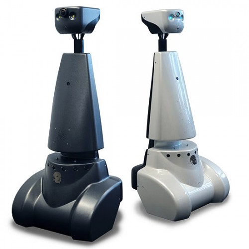
The objective of the Embedded Motion Control course is to acquire knowledge and insight about the design and implementation of embedded motion systems. Or more explicitly said it is about software design and application to autonomous robots. For the purpose of learning these objectives, practical assignments using the Pico and Taco robots shown in Fig.1 will be conducted. These assignment involve the robot autonomously solving the corridor and maze challenge.
Design Architecture
In this section overview of the system requirements, specifications, functions, components and interfaces is given.
Requirements
The requirements for the corridor and maze challenge were found and grouped using the FURPS method (Functionality Usability Reliability Performance Supportability).
- The Pico/Taco robot must solve the corridor and maze challenge.
- The corridor challenge must be solved within two attempts of maximum 5 minutes total.
- The maze challenge must be solved within two attempts of maximum 7 minutes total.
- Must not be at a standstill for more than 30 seconds.
- Maze solving algorithm must be implemented. It must be taken into consideration that the robot might start/be inside a loop or encounter a dead-end.
- Entire rear wheels must be across the finish line.
- The Pico/Taco robot must take the desired turns, not drive into walls and recognize doors.
- The Pico/Taco robot must operate autonomously.
- The Pico/Taco robot must be able to send a signal to open the doors.
- Only one executable has to be called to start the software.
- Use given hardware
- Design must be reliable.
- To validate the design it will be tested and simulated.
| Requirement | F | U | R | P | S |
|---|---|---|---|---|---|
| Solve corridor/maze | x | x | |||
| Navigate appropriately | x | x | |||
| Operate autonomously | x | x | |||
| Send signals | x | ||||
| Execution of software | x | ||||
| Use given hardware | x | ||||
| Reliable design | x |
Specifications
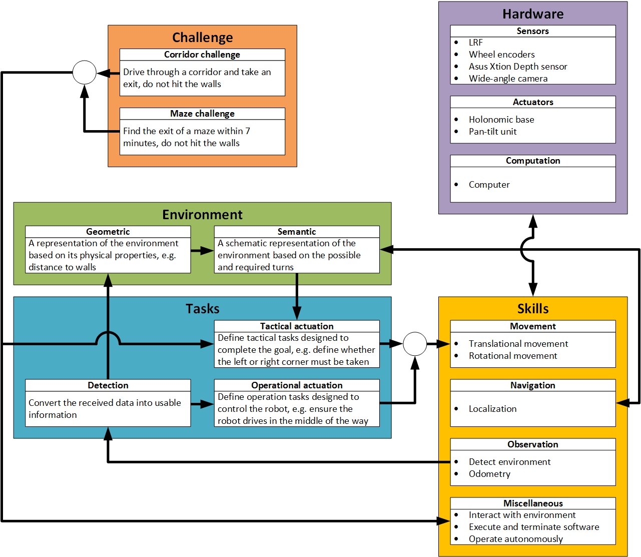
The specifications can be divided over different contexts, this can been seen in Fig 2. The following contexts were used:
Challenge: Challenges are Corridor and Maze Challenges. In both challenges PICO have to calculate and follow true trajectory for exit without any collision to walls within 5 minutes for Corridor and 7 minutes for Maze Challenge. In addition to a corridor, Maze Challenge contains loops, door and complicated maps.
Environment: For a better representation of the environment both geometric and semantic maps are made. Furthermore the geometric map is required to create the semantic map and detect doors.
Skills: Skills of the PICO robot that are satisfactory/sufficient in order to find its way out of the maze can be categorized into 4 groups: Movement skills provided by omni-wheels allow PICO to change its position and orientation along the maze, which is the most important capability to complete the challenges. Observational skills provided by the sensors allow PICO to detect its surroundings (corridors, corners, doors, etc.) which provides awareness to make other skills useful. Navigational skills come from the interpretation of the detected data through the selected maze solving algorithm, that provides a dynamically forming path (a global path is not possible since we don't have access to the entire maze at a given time) to make a way out of the maze. Other skills worth noting are enabled by the software running in real-time: Interacting with the environment when a relevant observation is made and the autonomous operation enabled (also limited) by the finite-state-machine.
Tasks: This contains the tactical actuation, operational actuation and detection. The tactical actuation defines tasks in order to complete the goal, while the operational actuation defines tasks to control the robot based on the detection task. The detection task converts received data into useful information and sends it to the operational actuation which decides upon a new control action.
Hardware: This contains the physical hardware of the robot. These are the sensors and actuators that have previously been discussed as well as the computer.
Functions
The following functions have been specified for the PICO robot.
- Basic movements in order to navigate through the corridor and maze challenge. These movements involve:
- Forward and backward movement
- Left and right rotation
- Wait in front of doors or dead end
- Reading sensor data
- Autonomous decision making
- Create a mapping and localization
- Include odometry
- Upon competition of the corridor and maze challenge the robot should terminate autonomously
Components
The Pico/Taco robot is consisted of the following sensors and actuators:
- Sensors:
- Laser Range Finder: By measuring the time of flight of the laser pulses (sent in a narrow beam) that reflect off the targets, LRF is used to detect the walls and the doors. Laser data is represented in polar coordinates, giving the distance and the angle to the obstacles in the range of the sensor. Note that the mapping capabilities of the robot is highly related to the head-on direction of PICO.
- Wheel encoders: The wheel encoders will allow the robot to estimate its position relative to the starting location. Odometry alone is not accurate enough, but together with the LRF it can determine the traveled distance and direction. For the odometry to be used effectively, rapid and accurate data collection, equipment calibration and processing is required.
- Asus Xtion Depth sensor: Xtion enables color image sensing and two lenses which provide depth detection. The distance of use is between 0.8 and 3.5 meters. This range specification provides us to avoiding waiting whole sliding duration of the door for detecting the door. Although the time duration of door sliding is 3 seconds, Xtion notices starting of the sliding and understand whether it is a door or a dead-end at the beginning. Therefore we will save approximately 3 seconds for each dead-ends that the PICO faces.
- 170° wide-angle camera: The wide range camera allows the robot to have a better perception of the environment. This will help the robot decide what direction is available to take.
- Actuators:
- Holonomic base: Three omni-wheels are used to move the robot. The robot can achieve speeds up to 0.5 m/s in translational direction and a rotational speed of 1.2 rad/s. If the robot rotates and translates simultaneously the turning radius will be just above 40 cm. It is however currently unknown if the hardware and preprogrammed software allows this.
- Pan-tilt unit: A pan-tilt unit is attached to the head; this allows the depth sensor to be rotated over two axes and aimed in a desired direction.
It also consists of a computer with an Intel i7 processor which is running on Ubuntu 14.04.
Interfaces
The following interfaces were defined between the different contexts:
Challenge – Tasks: Completing the challenges is the biggest picture. In order to achieve that goal, challenges need to be divided into smaller tasks that need to be fulfilled one step at a time.
Challenge – Skills: Challenges must be solvable with the existing skill set of the robot at hand (feasibility/existence of a solution)
Task – Environment: provides the information for building the geometric structure of the environment.
Environment – Environment: map geometric representation of the environment onto schematic representations that are proper for applying maze solving algorithms.
Environment – Tasks: sends the schematic representation of the environment data for deciding true movement in order to complete the challenge.
Environment – Skills: This interface provides information from the semantic model of the environment to the navigation skills which allows the robot to determine the location on the map.
Tasks – Skills: This interface selects the appropriate movement skills according to the information from the tactical and operational actuation and also sends information from the observation skills to the detection task.
Tasks – Tasks: The task of detection is linked to the task of operational actuation. When the surroundings are detected the robot can be operated accordingly; avoid bumping into walls and driving in the middle of the pathway.
Hardware – Skills: The hardware enables the skills of the robot. For example, movement skills are not possible without the holonomic base.
Corridor challenge
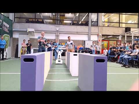
On May 18th the Embedded Motion Control #Corridor Competition was conducted. Our group succeeded in completing the challenge with time little over 17 seconds, which put us into 3rd place. The video of our attempt can be viewed by clicking on the picture below.
 |
Approach of the corridor
The code for the corridor challenge took advantage of the simplicity of this challenge. The robot moved forward in the initial straight corridor. The distance to both sides has been measured with the laser scanner in order to center the robot in lateral direction. If the distance to the right was larger the robot would move left and vice versa. A bundle of measurement points was used to avoid strong reactions to disturbances. Furthermore, if the distance was too great the robot would not react, this was aimed to avoid a strong reaction to gaps in the wall. This method was robust enough for this situation in which PICO would be approximately aligned with the corridor from the start. Thus, no advanced and more difficult code was used. In the meantime the environment was scanned for an exit, if such an exit was wide enough the applicable code was used to turn PICO.
First, the robot was directed to the center of the junction; this was based on odometry and the known width and location of the exit. Then odometry was used to rotate the robot 90 degrees in the direction of the exit. A potential field code was then used to move the PICO forward and into the exit. The potential field was aimed to correct for any inaccuracy in the odometry. A target that was always exactly in front of PICO at all times has been used for this. Once the walls on the side were sufficiently close PICO considered itself in the exit and used the initial alignment tactic to drive to the end of the corridor. These steps have been visualized in Fig.3.
 |
Analysis and learned lessons
During the corridor challenge two attempts have been used. It was found that during the first attempt the potential field pushed PICO out of alignment and made is scrape the wall at the exit. The wall on the right side was scraped, which caused the distance to the wall on the left side to be too big for the alignment code to work. This was due to the gap neglecting tactic. A combination of two additional pieces of code that were aimed to increase robustness (odometry correction and gap neglecting) thus caused PICO to not function optimally.
During the second attempt the potential field managed to keep the robot away from the wall. The alignment code then functioned correctly and PICO crossed the line in 17.5 seconds which was sufficient for a third place.
One improvement to this code was adjusting the code for the corridor, changing the threshold of distance at which it won’t react. In order to coop with open spaces the code has eventually been changed to a wall following code in combination with potential field. More information regarding this new code can be found further in this wiki page. Another change has been made regarding target placement and tracking with the potential field. This avoided future problems with using the potential field to reach targets.
Geometry detection
Along with the “movement” capabilities of the robot, detecting and interpreting the environment accurately is one of the most important low level tasks. This especially becomes important considering our approach to solve the maze since we need to list all the possible directions that the robot can go for the decision making. By this way, the robot is always making ‘aware’ movements, considering all the options and moving based on the interpreted environment and the decided direction instead of merely being directed by the potential field to move towards the most obvious gap in the maze.
Considering the perpendicular structure of the maze, we listed all possible geometries that can be encountered in the maze that either requires a decision making or a turn to be taken. These are: Straight-Right Junction, Straight-Left Junction, Right Corner, Left Corner, 4-way junction, T-junction, dead-end and a door. These geometries are scanned at each iteration of the loop unless PICO is still moving towards a target.
Note that stopping movement of the robot is taken as soon as an environment is detected in order to minimize the drifting from the last known point.
For further and more elaborate description on how these junctions are detected visit the following sub-page:
Potential field
General idea
For the ease of implementation, a straight forward potential field algorithm is used. The robot is “pushed away” by the walls in the proximity and “attracted” by the target points decided based on the decision making strategy. To provide a smooth movement for the robot, only the walls within 30 cm radius of the robot is taken into consideration when forming the resultant force vectors on the robot. Each wall point in the relevant radius of the robot pushes the robot inversely proportional to its distance to the robot. These forces are decomposed into x and y components in order to define the angle of the repulsive force, so that the robot can move towards the opposite direction of the resulting repulsive force. Target force of the robot is also normalized, based on the x and y direction of the target with respect to the robot. A snippet of the code used for the potential field can be found with the link at the bottom of this wiki page.
Use of target
The movement through the maze is done by placing targets inside the junctions that are detected, which will act as attracting forces for the PICO. With this it is ensured that the PICO will make the necessary turns. When no junction is detected, the target is placed one meter ahead of PICO, which makes it go straight. Two possibilities of the target placement were considered when a junction is detected and PICO needs to turn in a corner. In one of the methods the target is first set in the middle of the junction which will just make the robot move straight. After the target is reached, PICO starts to rotate in the desired direction. When the rotation is finished new target is placed inside the junction and with that PICO successfully drives into the corner. Taking that the width of the junction is known, a line from the junction with similar width is searched for. When such a line is found, the target is then placed in the middle of this line. The other method is when the target is set directly inside the junction. With this target placement PICO will directly steer inside the junction and the cornering will be smoother. Both methods are shown in Fig. 5.
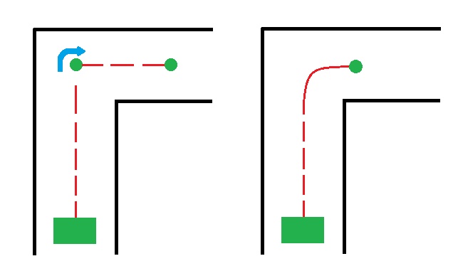
The first method was thought to be less robust because a misalignment on a junction or intersection may force the robot to go in an undesired direction. Another advantage to the second method of directly placing the target inside the junction was that it is more robust when there are two corners close to each other. Therefore, the choice for the movement of PICO was conducted with the direct method of target placement. A necessity for these methods of movement is keeping track of the target. When a geometry is detected relative targets are placed. These targets are then checked by the pledge algorithm and adequate movement determined, meaning there is only one target left. This target needs to then be transformed into a global target which is used for setting a definitive relative target and direction of movement. The movement is realized using the potential field and the target is updated in this mentioned loop. The transformation of the target from relative to global and vice versa is shown by these transformation matrices.


Where x,y are the x and y odometry position and α is the odometry angle.
Pledge algorithm
The Pledge algorithm is a modified version of the wall following algorithm such that it prevents getting stuck into loops. It’s guaranteed to reach an exit of any 2D maze from any point in the middle, without needing to mark or remember the path it takes. The Pledge algorithm has the following composition [1]. The robot starts by picking a direction and always moving in that direction when possible. When a wall is encountered, the robot should start wall following and count the number of turns it makes (e.g. right turn is -1, left turn is 1). The wall following is stopped when the total number of turns that the robot has made is zero (i.e. the counter is zero) and then move in the initially picked direction. The counting ensures that the robot won’t get stuck in a loop or a G shaped geometry and that eventually the exit will be found. The Pledge can however make the robot visit paths that have already been passed, although the counter will have a different value. For a more convenient way of keeping track of the counter, all situations that PICO might encounter are examined; as shown in Fig. 6. With this knowledge the counter value would be known for each situation and can easily be implemented in the appropriate code. A snippet of the code can be found at the bottom of this wiki page.
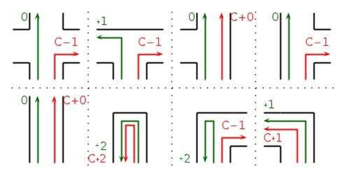

The simplicity of the algorithm and the fact that it ensures that PICO can exit the maze makes the Pledge algorithm suitable for the maze challenge. In Fig. 7 the maze that was used in the challenge is taken as an example to visually present the way this algorithm works.
Taken that the movement of the robot is done by placing targets and driving using potential field, the Pledge algorithm is strongly dependent on geometry detection. This can be a crucial disadvantage, because wrongly detected geometry may steer the robot in an undesired direction and with that making the counter value incorrect.
Due to the advantages that it brings, mainly with its simplicity, this algorithm is used for solving the maze challenge. The Pledge algorithm drew interest from other groups after the final presentation and was also implemented as their algorithm to solve the maze.
Structure of code
The structure of the code has been centered around the pledge algorithm for maze solving. A single threaded code with a refresh frequency of 10 Hertz has been used. This frequency was considered adequately high in order not to require multithreading. As cautionary procedure a second code with a lower movement speed of the PICO robot has been made. A snippet of the main code can be found at the bottom of this wiki page.
Fig.8 shows the topology of the code. Initially the robot is moving and scanning for geometry. The potential field is preventing the robot to crash while moving and the wall following may be deployed in order to move in the correct direction in open spaces. If geometry is detected, such as crossings or dead ends, the code will determine whether the robot will attempt to open a door or make a decision on where to move. After attempting to open a door the robot will scan for geometry again after waiting for 5 seconds. This way it will detect whether a door has been opened and where it can move. The picture shows that the robot may not detect geometry after trying to open the door; this may seem strange but considers the situation in which the door in a dead end opens and there is a normal corridor ahead. Once a geometry has been detected all possible directions are marked with a target.
The pledge algorithm is then used to decide which direction PICO should move towards. This can either be done by selecting one of the targets and using the potential field algorithm to move towards that target, or move 180 degrees based on odometry. Movement towards a target is stopped when the robot is within ten centimeters of the target. Rotation is stopped when the difference in angle according to odometry is 180 degrees.
This strategy is performed using a single threaded while loop; flags are used to keep track on what are the next steps required to travel through the maze. This furthermore ensures that a movement command is only send to the holonomic base once every iteration. This prevents an overflow of commands which can cause PICO to not react to new commands. Furthermore, flags are used to ensure that PICO will not infinitely check for a door when it encounters a potential door.
Open spaces
When an open-space is detected PICO finds the closest wall to its right and starts following it. The strategy that is used for the wall following is to maintain a set distance to a wall using a series of range measurements [2]. When a distance to the nearest obstacle is measured, it is possible to follow the surface by just moving in such a fashion that the smallest distance to a wall is perpendicular to the movement direction [2] . This allows for PICO to also take turns just with this algorithm. The open-space movement is illustrated in Fig.7. The wall following algorithm is a simple and efficient method for movement in open-spaces that worked sufficiently in the simulations and in the real maze and testing, which are the reasons why it was implemented in our strategy. Implementation of this in the code can be found in the code snippet for potential field at the bottom of this page.
Uniqueness
The most unique aspect of our code was the pledge algorithm. This simple but elegant solution was chosen to be able to finish the coding in the given amount of time. This algorithm is able to get out of any maze without requiring any form of mapping. The preconditions are that you start inside of the maze and finish outside; furthermore the direction of the robot must be known. These preconditions fit the context of the maze challenge, making this an ideal solution. The time saved by choosing this algorithm was used for optimization of robustness of the code.
Another uniqueness of our code is the coordination/communication between the decision making (pledge), movement (target setting and movement towards the target) and the detection (from low level edge detection to higher level geometry identification).
Maze challenge
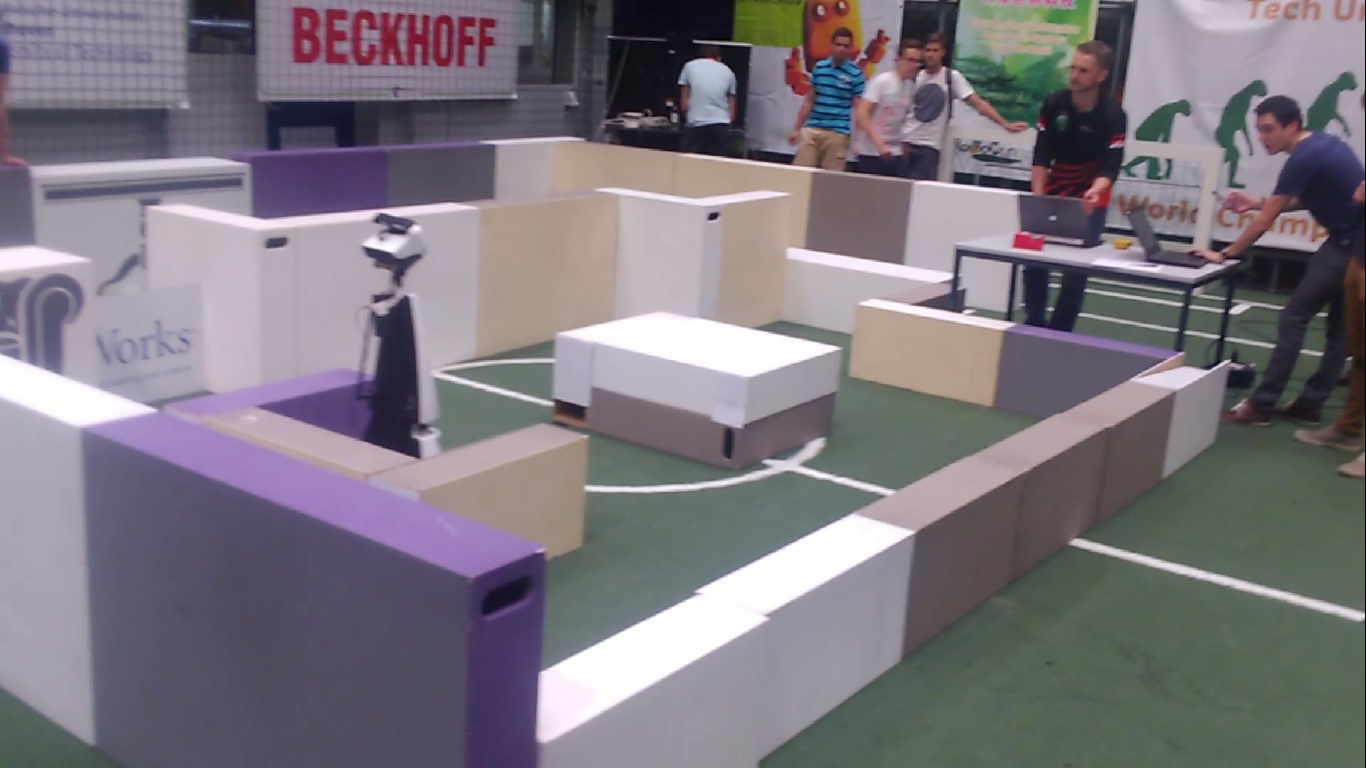
On 8th of June the Embedded Motion Control #Maze Competition was conducted. Unfortunately our group didn't succeeded in completing the challenge in both attempts. The videos of both attempts can be viewed by clicking on the pictures below.
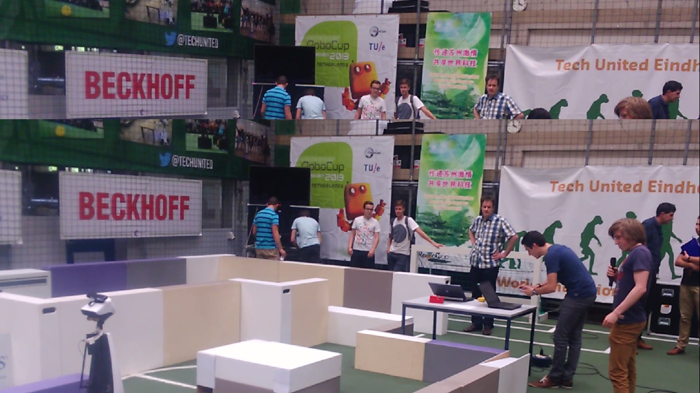 |
 |
Problems
First attempt
The first problem encountered in the maze challenge was with an unfamiliar geometry. Primarily the exit on the right was recognized with no exit to the left; this geometry was thus recognized as a T-junction. The recognition as T-junction caused the target to be placed straight ahead of the robot, this caused PICO to place its target inside of a wall; this can be seen in the picture. The robot would thus approach the wall head-on. In the first try the potential field was not quick enough in reacting to the approaching wall and thus PICO had a collision.
 |
Second attempt
In the second attempt the movement speed of PICO was lowered. Due to the fixed frequency of the coding loop PICO checked for possible collisions more frequently with respect to distance. The potential field was thus able to avoid hitting the wall at the first intersection. However, this still caused problems for PICO to reach its target as it was inside of the wall. Moving the wall luckily helped PICO to continue its attempt.
In the description of the maze challenge, the depth of the door was defined as approximately 30 cm. Based on this, valid depth of the door was defined in the ranges of 25-35 centimeters. However, in the actual maze challenge door depth was 40 cm, which is why it was failed to be detected.
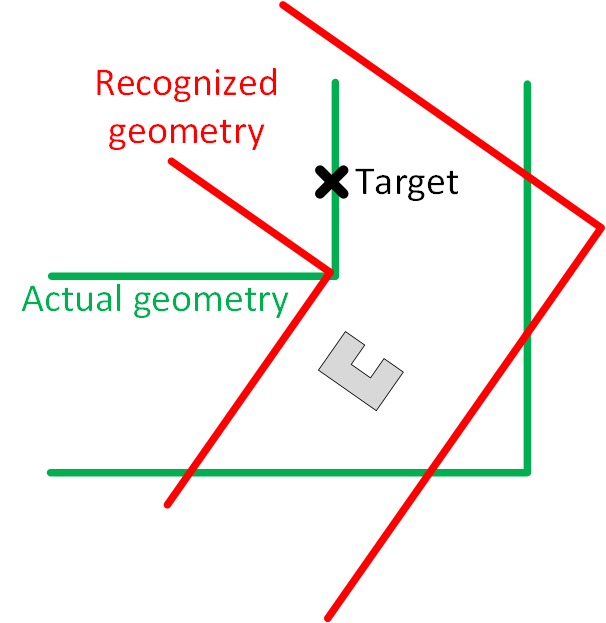
After missing the door PICO was strongly misaligned with the maze. This was due to the wall following and the unrecognized door. The misalignment caused PICO to put the target at the right relative to the distance ahead of it and its own pose with respect to the corner. The target thus once more ended up in the wall. As with the false T-junction this may be improved by detecting whether targets are not blocked when setting them. Furthermore, additional code may be implemented that recognizes a repetition of movements to ensure that PICO will stop attempting to reach this unreachable target.
 |
The target set overall was not robust enough and the geometries encountered in the maze were not encountered during testing or simulation. Perhaps, more serious thought into how to find situations in which the code may not be applicable could’ve prevented this.
Successes
- The first 3 geometries that the robot has encountered (2 T-junctions and a right corner) before the crash was identified correctly, since the robot navigated according to the pledge up until that point.
- With the altered movement speed the potential field algorithm did function correctly. It avoided crashes and was able to navigate PICO to a target (if reachable).
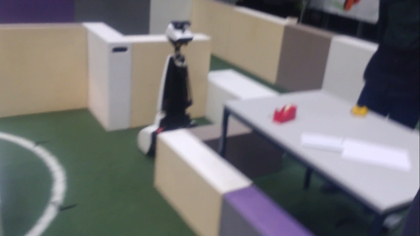
- The Pledge algorithm itself was a success and if the other issues weren’t there PICO would have solved the maze. To reassure ourselves that the algorithm works, after the challenge we ran a short test where the door would be open and PICO would start from a dead-end. This can be seen in the video below, where PICO indeed found the exit with use of this algorithm.
- The wall following code to coop with the open spaces was also successful. The third attempt after the challenge showed that PICO was able to follow the wall at open space. This helped with eventually successfully executing the pledge algorithm.
- Working code in the simulator as shown in the video below, where PICO successfully finds an exit from the maze.

Conclusion and recommendation
- The Pledge algorithm is a simple method that allows the robot to exit any maze. Only thing that has to be taken into account with this method is to have a robust geometry detection and movement.
- A top level crash avoidance and feasible target setting can be implemented.
- Awareness of the inter-loop behavior of the robot in the actual maze is highly important. When a movement or geometry update is being made, it needs to be made sure that the robot do not miss any other geometries or drive towards an infeasible target until the next update comes.
- A great deal of resources from previous years can be found on the wiki. Being aware of the challenges and possible problems that can be encountered is crucial. But in the end, implementing ideas in your own way is also very important.
Learning experiences
- Great hands-on experience
- Time and task management is crucial for this course
- Programming in C++; we had limited experience with this beforehand, but are now comfortable with the coding.
- You will fail lots of times. Don’t get discouraged by it
- No matter how good the robot moves and reacts in the simulator, the reality will be different. Therefore, make the code as robust as possible and use every test session that you can
- Use the help of the tutor as much as you can. We feel that this is something we could have improved on
- Have fun and enjoy
Sources
[1] Tom Kamphans and Elmar Langetepe- "The Pledge Algorithm Reconsidered under Errors in Sensors and Motion"
[2] Teruko Yata, Lindsay Kleeman and Shin'ichi Yuta- "Wall Following Using Angle Information Measured by a Single Ultrasonic Transducer"
Code snipets
- Main loop
https://gist.github.com/anonymous/86b23a489a7c83c4de0dcc80496286a7
- Pledge algorithm
https://gist.github.com/anonymous/64bcac4471d6c4aa7c820301496911a2
- Potential field
https://gist.github.com/anonymous/b5ed5f7e94dd17eabca70eb1b48a618d
Files
- Design Architecture Document
File:Design Architecture Group 1.pdf
- First Presentation
- Final Presentation