The Netherlands is currently facing a significant issue related to the aging concrete infrastructure, particularly regarding bridges, viaducts, and underpasses managed by Rijkswaterstaat. While concrete structures were initially designed to last for a long time (approximately 100 years), since around 2005, increasing traffic loads and evolving safety standards have exposed potential weaknesses in older infrastructure. The growing traffic volume and vehicle weight now exceed the original design expectations, and stricter regulations such as NEN 8700 and Eurocodes necessitate a thorough reassessment of the country's existing structures. Unlike new constructions, it is difficult to reinforce older structures, making precise recalculations essential to ensuring their safety and continued functionality. Rijkswaterstaat manages approximately 4,800 bridges and viaducts, part of the 90,000 such structures across the Netherlands, with a total replacement value of €65 billion. Most of these structures were built between 1960 and 1980, making them approximately 60 years old. Even structures such as these that have around 40 years of use left are showing concerning amounts of wear and tear. The issue is compounded by the reality that many of these aging bridges are nearing the end of their technical lifespan. This results in a significant challenge for maintenance, reinforcement, and potential replacement over the coming decades. Between 2040 and 2060, the Netherlands will face a critical challenge in replacing and renovating these aging bridges and viaducts and many of them will require major attention in the coming decades to ensure their structural safety and maintain the reliability of the country’s infrastructure.
The Netherlands is currently facing a significant issue related to the aging concrete infrastructure, particularly regarding bridges, viaducts, and underpasses managed by Rijkswaterstaat. While concrete structures were initially designed to last for a long time (approximately 100 years), since around 2005, increasing traffic loads and evolving safety standards have exposed potential weaknesses in older infrastructure. The growing traffic volume and vehicle weight now exceed the original design expectations, and stricter regulations such as NEN 8700 and Eurocodes necessitate a thorough reassessment of the country's existing structures. Unlike new constructions, it is difficult to reinforce older structures, making precise recalculations essential to ensuring their safety and continued functionality. Rijkswaterstaat manages approximately 4,800 bridges and viaducts, part of the 90,000 such structures across the Netherlands, with a total replacement value of €65 billion. Most of these structures were built between 1960 and 1980, making them approximately 60 years old. Even structures such as these that have around 40 years of use left are showing concerning amounts of wear and tear. The issue is compounded by the reality that many of these aging bridges are nearing the end of their technical lifespan. This results in a significant challenge for maintenance, reinforcement, and potential replacement over the coming decades. Between 2040 and 2060, the Netherlands will face a critical challenge in replacing and renovating these aging bridges and viaducts and many of them will require major attention in the coming decades to ensure their structural safety and maintain the reliability of the country’s infrastructure. Rijkswaterstaat faces several challenges in addressing these issues:
Rijkswaterstaat faces several challenges in addressing these issues:
# '''Technical Challenge''' – Ensuring the ongoing safety and functionality of aging bridges and viaducts.
# '''Technical Challenge''' – Ensuring the ongoing safety and functionality of aging bridges and viaducts.
Line 37:
Line 34:
# '''Human Safety''' – Traditional inspection methods are hazardous, particularly for inspectors who need to climb or navigate dangerous parts of the bridge, and traffic closures affect public safety.
# '''Human Safety''' – Traditional inspection methods are hazardous, particularly for inspectors who need to climb or navigate dangerous parts of the bridge, and traffic closures affect public safety.
To help alleviate some of the burden on Rijkswaterstaat, our team proposes the development of a semi-automated data collection system designed specifically for the general inspecting of concrete bridges. General inspecting does not include thorough inspection methods that dive deeper into the structural state of the bridge and consists mainly of surface analysis which means the design of '''Crack detection robot''' can be cheaper and easier to maintain. However since there are approximately 4800 concrete bridges and they all need to be inspected at least once every 6 years Rijkswaterstaat needs to inspect 800 concrete bridges per year which is a significant workload for its current human resources.. This system, referred to as '''Crack detection robot''', is intended to streamline the inspection process and reduce the time and resources required for thorough assessments making inspections cheaper, faster and safer. Cheaper because there is less need for material and human resources to complete the inspection, faster and safer because there would be no need to close traffic and set up the inspection especially for difficult to access bridges like ones on top of water or ones that are too tall. '''Crack detection robot''' achieves this by being a wireless semi autonomous robot with instruments like high quality cameras in order to take the tens of thousands of pictures which are typical for inspections. The project will research what is required to create such a system, are drones better or should other alternatives be taken into consideration. What are good types of cameras and detections methods for structural defects, can AI be used and so on.
To help alleviate some of the workload faced by Rijkswaterstaat, our team proposes a semi-automated data collection system aimed at facilitating the general inspection of concrete bridges. These general inspections are conducted every six years and focus primarily on surface-level analysis, rather than in-depth structural assessments. With approximately 4,800 concrete bridges under its management, Rijkswaterstaat must inspect around 800 structures per year, a considerable burden on current human resources. Our proposed solution, initially envisioned as a "Crack Detection Robot", seeks to streamline this process by reducing inspection time, costs, and safety risks. The system would eliminate the need for extensive traffic closures and complex setups, especially for difficult-to-access bridges, such as those over water or at significant height. It would rely on wireless, semi-autonomous robots equipped with high-resolution cameras to capture the tens of thousands of images typically required for inspections.
While the original concept focused on designing such a robotic system, the project has since pivoted to researching the feasibility of using thermal cameras mounted on drones to enhance crack detection capabilities. This new direction explores whether drones offer a more effective and practical alternative for bridge inspections by using thermal cameras to make crack detection easier. Thermal cameras also come with the added benefit of providing more information on the cracks such as depth and width which would normally be inaccessible for general inspections.
== USE ==
== USE ==
=== Users ===
=== Users ===
Bridge inspectors and maintenance personnel have specific needs when it comes to robotic inspection systems, as highlighted in an interview with Dick Schaafsma, the highest strategic advisor for Bridges and Viaducts at Rijkswaterstaat. He pointed out that one of the biggest challenges in bridge inspections is the necessity to close bridges for safety, which can lead to significant traffic disruptions. For instance, closing a bridge for inspection can reroute large trucks through city centres, causing potential hazards and public backlash if accidents occur. Therefore, Rijkswaterstaat seeks a system that allows for inspections without shutting down bridges. Additionally, inspecting high or waterway bridges presents challenges beyond safety, as they often require specialised equipment and can be hard to access in certain areas. The benefits of using robotic inspection systems include improved accuracy, reduced inspection time through simultaneous and more efficient inspections, and increased safety while minimising traffic disruptions. To effectively use these robotic systems, current inspectors will need training to integrate this technology into their current workflows. Nonetheless, challenges such as maintenance costs, legal restrictions on drone usage, and safety concerns about operating equipment around traffic must be addressed. Despite these challenges, Schaafsma expressed enthusiasm for the potential of robotic systems and AI to improve bridge inspections, while still emphasising the importance of having a human involved in the process to ensure reliability and effectiveness.
Bridge inspectors and maintenance personnel have specific needs when it comes to robotic inspection systems, as highlighted in an interview with Dick Schaafsma, the highest strategic advisor for Bridges and Viaducts at Rijkswaterstaat. He pointed out that one of the biggest challenges in bridge inspections is the necessity to close bridges for safety, which can lead to significant traffic disruptions. For instance, closing a bridge for inspection can reroute large trucks through city centres, causing potential hazards and public backlash if accidents occur. Therefore, Rijkswaterstaat seeks a system that allows for inspections without shutting down bridges. Additionally, inspecting high or waterway bridges presents challenges beyond safety, as they often require specialised equipment and can be hard to access in certain (drones in this case) areas. Drone-based inspection systems—like the ones being explored in this project—can significantly reduce inspection time, improve safety, and minimize traffic impact. However, implementing such systems also requires training current inspectors to use and interpret data from this new technology. In the case of drones, there is already simulation software available to support pilot training. There are also challenges, such as maintenance costs, legal restrictions (e.g., licensing requirements, flight path limitations near sensitive areas like military zones), and safety concerns when operating drones near live traffic. Despite these hurdles, Schaafsma expressed optimism about the potential of robotic and AI-driven systems in improving inspection quality, while emphasizing that human oversight remains essential to ensure the reliability of assessments.
=== Society ===
=== Society ===
Society and users are largely intertwined regarding this technology. Bridges in the Netherlands are under government supervision; the government is a societal stakeholder and partly a user. Dick Schaafsma emphasized that they will not directly be a user but will instead pay a company that handles the technology and then provides the information to Rijkswaterstaat, although this could change in the future if it decides to become internal. In addition to the governmental agencies that will obviously benefit from this technology, so will the general public, another significant stakeholder from a societal perspective. When correctly implemented, the general public can enjoy safer bridges and a more reliable traffic network. Road users might have concerns or questions when, for example, they soon see flying drones above the road or around the bridge conducting inspections. For this reason, it is important that the government informs communities about the benefits and implementation of this technology, as well as the associated (low) risks involved for the general public. Lastly, the technology must comply with laws, regulations, and standards that are already in place regarding safety and reliability.
Society and users are largely intertwined regarding this technology. Bridges in the Netherlands are under government supervision; the government is a societal stakeholder and partly a user. Dick Schaafsma emphasized that they might not directly be a user but may instead outsource the actual flying to professional drone pilots which will be accompanied by inspectors. Rijkswaterstaat can then use the data to form reports on each specific bridge as is done now. In addition to the governmental agencies that will obviously benefit from this technology, so will the general public, another significant stakeholder from a societal perspective. When correctly implemented, the general public can enjoy safer bridges and a more reliable traffic network. Road users might have concerns or questions when, for example, they soon see flying drones above the road or around the bridge conducting inspections. For this reason, it is important that the government informs communities about the benefits and implementation of this technology, as well as the associated (low) risks involved for the general public. Lastly, the technology must comply with laws, regulations, and standards that are already in place regarding safety and reliability.
=== Enterprise ===
=== Enterprise ===
Line 52:
Line 51:
== Objectives ==
== Objectives ==
* Discuss the ethical implications of semi-autonomous bridge inspection systems, particularly regarding data privacy, workforce impact, and liability in infrastructure assessment.
* Explore the ethical and legal considerations associated with using drone-based bridge inspection systems, including issues of data privacy, regulatory compliance, workforce displacement, and liability in infrastructure monitoring.
* Compare and research methods for detecting surface defects in concrete bridges, including high-resolution imaging, sensor-based inspection, and other non-destructive techniques.
* Investigate and compare methods for surface defect detection in concrete bridges, with a focus on the potential of thermal imaging.
* Develop a system for determining the severity of detected structural defects and classifying them for maintenance priority according to safety standards.
* Assess the viability of thermal cameras for detecting cracks and structural anomalies in the Netherlands.
* Develop a conceptual model of a semi-autonomous robotic bridge inspection system that can efficiently collect and analyze bridge surface data.
* Evaluate the applicability of AI-based techniques for enhancing defect detection with thermal cameras.
* Research and design an AI-based system for the system's effectiveness in defect detection and classification, considering the feasibility of machine learning techniques in bridge inspection.
* Compare the efficiency, safety, and reliability of drone-based infrared inspection systems with conventional manual inspection methods, including time, cost, and data quality aspects.
* Assess the feasibility of different mobility options, such as drones or other robotic systems, to determine the most suitable means of bridge inspections.
* Assess the effectiveness of the system by comparing its performance with conventional manual inspection methods.
== Approach, milestones and deliverables ==
Our '''approach''' to reaching these objectives in regards to the problem statement and the user needs is as follows:
We want to research and design a conceptual framework of a robot that is able to detect cracks in bridges and map these out on a geographical map, for the benefit of bridge maintenance and infrastructure longevity. We will (partly) perform the first cycle of a multi-phase development cycle consisting of the following phases:
* Identify the practical limitations and operational challenges of implementing drone-based inspection systems, such as legal flight restrictions, training requirements, and environmental conditions.
* Research & requirements gathering
Note: Due to the time constraints of the course not all objectives are possible, the focus was on researching if the thermal camera approach is even possible
** This includes both: Conducting an interview with stakeholders in the bridge maintenance problem and research in the technology needed to build this robot.
* Sensor and other hardware selection
* Explain different types of cracks and crack detection in bridges
* Build a model/PoC (Proof of Concept)
Along these phases of our first development cycle we will set some '''milestones''' for ourselves as to keep our attention on the objectives set. This will be in the form of documentation of our work in a structured manner, making sure that the work put into each phase is represented. This documentation will in turn be part of our '''deliverables''', as will be the model/PoC of our bridge crack detecting robot.
== Approach, milestones and deliverables ==
To address the problem statement and meet the identified user needs, our approach focuses on researching and evaluating the potential of drone-based thermal imaging systems for bridge inspection. Instead of developing a complete robotic solution, our goal is to investigate the feasibility and added value of this specific technology in enhancing surface crack detection. A lack of research for this specific use of thermal cameras especially for colder climates like the Netherlands along with their added benefits like cost, AI integration etc. inspired the team to do the research.
== Technical Requirements ==
We aim to design a conceptual framework for a drone-based inspection system that leverages thermal cameras and AI-based image analysis to detect and localize structural cracks in concrete bridges. The system is intended to support infrastructure maintenance by improving data collection efficiency, reducing safety risks, and enabling more predictive maintenance planning.
* Bridge condition monitoring (way to detect and take photos of cracks of 0.2mm)
We will carry out the first cycle of a multi-phase development process, consisting of the following key phases:
* Data collection and a sufficiently large storage module (unspecified will be specified in the second interview)
* Semi automation (needs a driver but robot knows exact location and some other things about automation)
* Remote/wireless operation (real time camera for navigation and range)
* Battery life (can for example use battery packs that are swappable so no need to recharge every time)
* Cheap
* Easy to maintain/fix (can use 3d printed parts so if something breaks it is easy to fix)
* User friendly/easy to use
* Size (cant be too big)
* Integration into existing pipeline (expand)
* Able to access hard to reach parts of bridges like the underside and columns
* Safe for user and people around it (small, lightweight, consistency)
* Weight lifting capacity (the robot should be able to lift itself and the measuring equipment/cameras)
Requirements still need quite a bit more specifications
# '''Research & Requirements Gathering'''
#* Conduct interviews with relevant stakeholders (e.g., bridge inspection experts at Rijkswaterstaat)
#* Review current technologies in drone-based inspection, infrared imaging, and defect detection in concrete structures
# '''Technology Exploration'''
#* Analyse the use of thermal cameras for crack detection
#* Investigate AI-based methods for detecting and classifying and analysing surface defects
# '''Conceptual Design & Proof of Concept'''
#* Develop a conceptual system model integrating drone, sensor, and AI components
#* Make a test plan and test the ability of thermal cameras in real life environments
#'''Conclusions'''
#*Results and conclusions of the tests
#*Limitations of the design, technology and the approach
#*Future research to complete
== Planning ==
== Planning ==
Line 123:
Line 114:
|-
|-
|4
|4
|Design limitations
|System overview and design
Second interview (feedback on first design)
Technical Design
Technical design discussion of second design and the second design as a whole
|reached
|
|-
|-
|5
|5
|Finish Technical design discussion of second design and the second design as a whole
|Finish Technical design
Start actual experiments
Start actual experiments
|
|reached
|-
|-
|6
|6
|Actual experiments and results
|Actual experiments and results
|
|reached
|-
|-
|7
|7
|Critical evaluation of the design performance and utility
|Critical evaluation of the design performance and utility
Make presentation
Make presentation
Finish the wiki
Finish the wiki
Conclusions
Conclusions
|
Future research
|reached
|}
|}
== State of the art ==
=== Detection ===
===== 3D vision technologies for a self-developed structural external crack damage recognition robot =====
This papers discusses the viability of multiple 3D vision techniques for detecting external cracks in infrastructure. This includes image based methods that only recently gained some adaptability, point cloud based methods that require substantial computational resources and 3D visual sensing and measuring methods such as 3D reconstruction. According to the article all methods presented lack one of three things: weight (the technology is usually to heavy), precision (to 0.1mm accuracy required for diagnosis) and robustness and accuracy. The authors then go to present a new type of automatic structural 3D crack detection system based on the fusion of high-precision LiDAR and camera which is more lightweight combines the depth sensing of LiDAR with the detailed imagery of the camera and has the required real time precision for safety diagnostics.
===== ROAD: Robotics-Assisted Onsite Data Collection and Deep Learning Enabled Robotic Vision System for Identification of Cracks on Diverse Surfaces =====
This paper discusses the architecture of ROAD (Robotics-Assisted Onsite Data Collection System) as a means of automatically detecting cracks and defects in road infrastructures. The paper looks into traditional methods of crack detection and their limitations and encourages the use of deep learning in crack detection. The paper also discusses the effectiveness of multiple deep learning algorithms in detecting cracks on roads and concludes that Xception has the best performance with an accuracy over 90% and mean square error of 0.03. More generally the paper claims that deep learning algorithm trained in good datasets outperform the traditional methods. The reason why the authors push for ROAD is due to the lack of automation when it comes to traditionally detecting cracks in roads and therefore introduces ROAD (Robotics-Assisted Onsite Data Collection System), which integrates robotic vision, deep learning, and Building Information Modeling (BIM) for real-time crack detection and structural assessment.
===== Novel pavement crack detection sensor using coordinated mobile robots =====
The paper proposes the design of an integrated unmanned ground vehicle (UGV) and drone system for real-time road crack detection and pavement monitoring. A drone conducts an initial survey using image analysis to locate potential cracks, while the UGV follows a computed path for detailed inspection using thermal and depth cameras. The collected data is processed using MATLAB and CrackIT, enhanced by a tailored image processing pipeline for improved accuracy and recall. A crowd-sourced crack database was developed to train and validate the system. Webots software was used for simulation, demonstrating the system’s effectiveness in structural health monitoring. The proposed system offers high mobility, precision, and efficiency, making it suitable for smart city applications.
===== Pixel-Wise Crack Detection Using Deep Local Pattern Predictor for Robot Application =====
This study introduces a novel crack detection method using a Convolutional Neural Network (CNN)-based Local Pattern Predictor (LPP). Unlike traditional methods that classify patches, this approach evaluates each pixel’s probability of belonging to a crack based on its local context. The proposed seven-layer CNN extracts spatial patterns, making the method robust to noise, lighting variations, and image degradation. Experiments using real-world bridge crack images demonstrate superior accuracy over existing methods (STRUM and block-wise CNN). The study also explores optimized sampling techniques and Fisher criterion-based training to enhance performance when datasets are limited. The method shows potential for real-time crack detection in robotic vision applications.
===== Development of AI- and Robotics-Assisted Automated Pavement-Crack-Evaluation System =====
The paper presents AMSEL, a semi-automated robotic platform designed to inspect pavement cracks in real-time using a deep learning model called RCDNet. The system uses both manual and automated navigation to collect data indoors and outdoors, with RCDNet detecting cracks based on image analysis. Despite some limitations, such as difficulty detecting cracks smaller than 1 mm and issues with lighting and shadow interference, the system provides an efficient alternative to manual inspections. Future improvements include integrating non-destructive testing (NDE) sensors, expanding the use of visual sensors for faster coverage, and developing deep learning models that can fuse data from multiple sources for more comprehensive defect detection.
===== Robotic surface exploration with vision and tactile sensing for cracks detection and characterization =====
The paper Robotic Surface Exploration with Vision and Tactile Sensing for Cracks Detection and Characterization suggests a hybrid approach to crack detection by complementing vision-based detection with tactile sensing. The system first employs a camera and object detection algorithm to identify potential cracks and generate a graph model of their structure. A minimum spanning tree algorithm then plans an effective exploration path for a robotic manipulator that reduces redundant movements.
To improve the accuracy of detection, a fiber-optic tactile sensor mounted on the manipulator verifies the presence of cracks, removing false positives from lighting or surface textures. Once verified, the system performs an in-depth characterization of the cracks, pulling out significant attributes such as length, width, orientation, and branching patterns. The two-sensing modality yields more precise measurements than traditional vision-only methods.
Experimental validation demonstrates that this integrated approach significantly enhances detection accuracy while reducing operating costs. By optimizing motion planning and reducing reliance on full-surface scanning, the system offers a more efficient and less expensive method of automated infrastructure inspection and maintenance.
===== Complete and Near-Optimal Robotic Crack Coverage and Filling in Civil Infrastructure =====
The paper Complete and Near-Optimal Robotic Crack Coverage and Filling in Civil Infrastructure proposes a new approach for autonomous crack inspection and repair with a simultaneous sensor-based inspection and footprint coverage (SIFC) planning scheme. The method blends real-time crack mapping and robot motion planning for effective and complete inspection. Integration of sensing and actuation through sensing and actuation integration makes the system efficient by avoiding redundant motion and providing optimal crack coverage.
The robot takes a two-step strategy, first, onboard sensors are used to detect and map cracks in real-time and calculate an optimal path of coverage using a greedy exploration algorithm. Second, a robotic manipulator follows the path and dispenses crack-filling substances where needed. The algorithm adjusts its path in real-time based on new cracks, allowing the system to react to irregular and complex surfaces without pre-computed structural maps.
Experimental results reveal that this system significantly improves the detection and effectiveness of crack repairs at a lower cost of operation. Through ensuring total crack coverage with minimal travel distance, the system outshines traditional procedures, making it a promising alternative for extensive rehabilitation of infrastructure.
===== Crack-pot: Autonomous Road Crack and Pothole Detection =====
The paper Crack-Pot: Autonomous Road Crack and Pothole Detection proposes an autonomous real-time road crack and pothole detection system using deep learning. This system employs a neural network architecture to handle road surface textures and spatial features, enabling the discrimination between damaged and undamaged areas. The approach improves the accuracy by reducing the misclassification due to environmental factors like lighting variations and surface unevenness.
The detection is carried out by capturing road images through a camera-based system mounted on an automobile or robotic platform. The images are input into a convolutional neural network (CNN) which identifies cracks and potholes based on their unique structural features. Compared with traditional thresholding-based methods, the learning-based approach is made versatile under different conditions with better robustness against occlusions, shadows, and background noise.
Experimental results show that the system achieves high accuracy of detection while operating in real-time, making it feasible for monitoring large-scale infrastructure. By automating road inspection, this method enhances efficiency and reduces the need for manual inspections, resulting in more proactive and cost-effective road maintenance procedures.
===== Visual Detection of Road Cracks for Autonomous Vehicles Based on DeepLearning =====
The research article Visual Detection of Road Cracks for Autonomous Vehicles Based on Deep Learning and Random Forest Classifier presents a high-tech image-based approach towards detecting road cracks based on the combination of deep learning and machine learning methods. The study integrates convolutional neural networks (CNNs) with a Random Forest classifier to improve accuracy in identifying faults in road surfaces. The method is intended to assist autonomous cars in driving over faulty roads while contributing to the maintenance of the infrastructure as well.
The system utilizes three state-of-the-art CNN models: MobileNet, InceptionV3, and Xception, trained on a 30,000 road image dataset. The learning rate of the network was tuned in experimentation to 0.001, yielding a maximum validation accuracy of 99.97%. The model was also tested on 6,000 additional images, where it recorded a high detection accuracy of 99.95%, demonstrating robustness under real-world conditions.
The results demonstrate the hybrid deep learning and machine learning technique significantly enhances crack detection accuracy compared to traditional methods. With its integration into autonomous vehicle technology or roadway maintenance initiatives, the technique offers a highly scalable, effective solution for real-time infrastructure monitoring and defect detection.
===== Article Deep Learning Based Pavement Inspection Using Self-Reconfigurable Robot =====
The paper Deep Learning-Based Pavement Inspection Using Self-Reconfigurable Robot introduces a robot system utilizing deep learning to conduct real-time pavement inspection and defect detection. The robotic system is centered on Panthera, a self-reconfigurable robot utilizing semantic segmentation and deep convolutional neural networks (DCNNs) for the detection of road defects and environmental obstructions such as litter.
The inspection process has two primary components: SegNet, a deep learning model that delineates pavement areas from other objects, and a DCNN-based defect detection module that detects different types of road defects. To enhance the system's usability in practical applications, it is integrated with a Mobile Mapping System (MMS) that geotags cracks and defects detected, allowing for precise location tracking. The Panthera robot has NVIDIA GPUs, which enable real-time processing and decision-making functions.
Experimental testing confirms that the system is highly accurate in detecting pavement damage and functions well under diverse urban environments. The technique not only optimizes the effectiveness of autonomous road maintenance and cleaning but also provides a scalable means for intelligent infrastructure management, reducing the need for manual inspections.
=== Vehicle/movement ===
===== [11] The Current Opportunities and Challenges in Drone Technology =====
This recently published paper discusses the the advancements that Drone Sensor Technology and Drone Communcation Systems have made, after which it defines some opportunities and challenges that the field of drone technology faces and it draws some conclusions on where it thinks this technology is headed and the general importance this field will have in certain industries.
It discusses the applications of Drone technology in the sectors Agriculture, Healthcare, and Military & Security. According to the paper, drones have already started being a critical too in the Agriculture sector as they perform crop monitoring and analysis to detect diseases early, leading to improved yields, but also Livestock monitoring by tracking movements and using thermal cameras. Healthcare has started using drones for medical supply deliveries and emergency response: drones can easily get crucial supplies to hard-to-reach areas. Drones are also being used by the military for surveillance and reconnaissance and higher precision of (air-)strikes. This leads to less colateral damage and enhances battlefield efficiency.
The paper states some opportunities pertaining to these previously mentioned sectors, but more interestingly it states some challenges that it believes drone technology faces, that can be important to many sectors besides these 3. It mentions that current regulations and legal frameworks limit the use of drones immensely, and drones are prone to cybersecurity threats, being at the risk of hacking and unauthorized control. It also names some technical limitations such as limited battery life, payload capacity and drone costs being high.
===== [A] Drone Technology: Types, Payloads, Applications, Frequency Spectrum Issues and Future Developments =====
This paper discusses various aspects of drone technology, such as types of drones, levels of autonomy, size and weight, payloads, energy sources, and future developments. Although the paper was published in 2016—9 years ago—a lot of the core technology remains the same, albeit more efficient and better built. Here, we'll summarize some parts briefly.
There are three main classes of drones: fixed-wing systems, multirotor systems, and other systems, such as ornithopters or drones using jet engines. Fixed-wing and multirotor systems are the most used and important. The first class is built for fast flight over long distances but requires a landing strip to take off and land. Benefits of the latter include reduced noise and the ability to hover in the air.
The United States Department of Defense distinguishes four levels of autonomy: human-operated systems, human-delegated systems, human-supervised systems, and fully autonomous systems. A distinction is made between autonomous systems and automatic systems: "An automatic system is a fully preprogrammed system that can perform a preprogrammed assignment on its own. Automation also includes aspects like automatic flight stabilization. Autonomous systems, on the other hand, can deal with unexpected situations by using a preprogrammed ruleset to help them make choices."
This requires energy. There are four main energy sources: traditional airplane fuel, battery cells, fuel cells, and solar cells. Airplane fuel is mainly used in large fixed-wing drones, while battery cells are the most common in smaller multirotor drones. Fuel cells are not widely used—one reason being that these types of cells are relatively heavy—so only larger fixed-wing drones can be equipped with them. Solar cells are also not often used in the drone industry. Low efficiency is one of the reasons for their limited application.
Lastly, the paper expects three major developments in the coming years in terms of drone technology, namely miniaturization (i.e., smaller and lighter drones), greater autonomy (i.e., more autonomous drones), and swarms (i.e., more drones that can communicate with each other).
===== [B] ANAFI Ai Photogrammetry =====
Parrot is a leading French drone manufacturer that focuses exclusively on professional-grade drones, offering two options: the ANAF Ai and ANAFI USA. As they say, “With our professional drones, we provide best-in-class technology for inspection, first responders, firefighters, search-and-rescue teams, security agencies, and surveying professionals.” Going into more depth, the ANAF Ai is capable of photogrammetry, which is the process of creating visual 3D models from overlapping photographs. Some key features of this drone are its 48 MP camera that can capture stills at 1 fps, compatibility with the PIX4D software suite, in-flight 4G transfer of data to the cloud, and the ability to create a flight plan with just one click. The ANAFI Ai is equipped with a camera that tilts from -90° to +90°, making it ideal to inspect the underside of bridges. Perception systems ensure the safety of the flight plan, so users don't need to worry about obstacles. The ANAFI Ai avoids them autonomously.
===== [C] DJI Bridge Inspection =====
Another leading drone manufacturer, and by far the biggest, is a Chinese company called DJI (short for Da-Jiang Innovations). This company offers an immense amount of products to the market—not just drones, but also power supplies, handheld cameras, and drive systems for e-bikes. Their primary specialization, however, is drones. Their range is vast, encompassing consumer camera drones, specialized agriculture drones for crop treatment, delivery drones, and enterprise drones for business use cases. On their website, they describe the different use cases and provide corresponding "solutions." These solutions combine a base drone platform, various payloads, software packages, and recommended workflows. For example, for bridge inspection, they provide three different solutions. One of these, their "Bridge Digital Twin Asset Management" solution, features the Matrice 350 RTK base drone (weighing approximately 6.47 kg) with payloads such as the Zenmuse P1—a 45 MP full-frame camera—and the Zenmuse L2, a LiDAR sensor. In addition, DJI Pilot 2, DJI Terra, and DJI Modify are software packages that integrate seamlessly to create an efficient workflow. Other solutions involve fewer sensors and smaller drones, allowing potential buyers to customize the possibilities.
===== [D] Drone-enabled bridge inspection methodology and application =====
This paper explores using drones for inspecting bridges as an efficient, low-cost alternative to traditional methods. With many bridges deteriorating, as noted by the ASCE, the study focuses on a timber bridge near Keystone, South Dakota, using a DJI Phantom 4. Researchers developed a five-stage inspection method based on extensive literature review and current practices. The results showed that the drone produced measurements and images comparable to those of conventional inspections while reducing time and risk to inspectors. The study demonstrates that drone technology can support legally mandated inspections and offers potential benefits in cost savings, safety, and data quality for future infrastructure assessments.
===== [E] Bridge Inspection with an Off-the-Shelf 360° Camera Drone =====
This study by Andreas Humpe examines how an off-the-shelf 360° camera drone can be used to inspect bridges. The research shows that using an easily available drone equipped with a 360° camera is a practical and cost-effective alternative to traditional inspection methods. The drone captures comprehensive, high-quality images from all directions, making it easier to spot damages and structural issues. By reducing the time and risk involved in manual inspections, this approach can improve safety and efficiency. The findings suggest that such technology could play a significant role in modernizing bridge inspection practices and supporting reliable maintenance decisions.
=== Communication ===
===== [12] THz band drone communications with practical antennas: Performance under realistic mobility and misalignment scenarios =====
This recently published paper explores the role of Terahertz (THz) band communications in 6G non-terrestrial networks (NTN), focusing on drone-based connectivity, spectrum allocation, and power optimization. Drones are expected to act as airborne base stations, enabling high-speed, ultra-reliable connectivity for applications like surveillance, sensing, and localization.
The study evaluates the true performance of THz drone links under real mobility conditions and beam misalignment, finding that while data rates of 10s to 100s of Gbps are achievable, severe performance degradation can occur due to misalignment and antenna orientation changes. It analyzes three channel selection schemes (MaxActive, Common Flat Band, and Standard) along with two power allocation strategies (Water-Filling and Equal Power), identifying a commonly available THz band for stable transmission.
The paper highlights major challenges for THz drone communications, including frequency selectivity, beam misalignment, and mobility-induced disruptions. It emphasizes the need for active beam control solutions to maintain reliable performance. While THz technology offers vast bandwidth potential, overcoming alignment and stability issues is critical for practical deployment in 6G drone networks.
===== '''[13] Redefining Aerial Innovation: Autonomous Tethered Drones as a Solution to Battery Life and Data Latency Challenges''' =====
This article explores the idea of using drones connected to a power supply through tethering it to one. It mentions that flight durations typically range between 20 and 55 minutes, and that this could result in having to frequent recharging or battery replacements which disrupts operations. Additionally it mentions that this way, communication can also be done through this tether which removes the problem of data latency and would allow for more responsive controls and transferring data like images to an external storage, removing the need of a SSD card or other storage module on the vehicle itself.
The study highlights the technological advancements that enable tethered drones to operate efficiently. Modern tether designs incorporate lightweight yet durable materials capable of transmitting power and data at high speeds. Some models use fiber optic cables to achieve data transmission rates of up to 10Gbps, significantly reducing latency. Despite these advantages, tethered drones come with their own set of challenges consisting of mobility restrictions due to the physical tether, but also the vulnerability to environmental conditions such as winds and rain. It proposes future potential developments such as improved tether materials, better autonomous navigation and integrating 5G technology. It concludes stating that it is a innovative solution in the UAV technology for applications requiring long flights in which battery life is an issue.
=== Main system ===
===== [14] '''Drone-Based Non-Destructive Inspection of Industrial Sites: A Review and Case Studies''' =====
This paper explores the increased use of unmanned aerial vehicles (UAV) for inspecting industrial sites through non-destructive inspection methods. It speaks of advantages over manual inspections performed by humans in the forms of enhanced safety, cost reduction and easier access to hard-to-reach areas. It discusses different inspection techniques like thermography, visual inspection and ultrasonic mapping. The paper also identifies challenging areas such as battery limitations, vibration effects on sensors and environmental factors affecting data accuracy.
The paper also presents different applications of these UAV inspections including bridge condition assessments and specifically mentions that drones can assist in detecting cracks, delaminations and corrosino in concrete structures such as bridges and buildings, being of great use in the field of preventive maintenance. It gives a few case studies in this bridge maintenance sector as well as other sectors, and finally emphasizes the need of further research and development in drone stability, sensor accuracy and automated defect detection algorithms.
==== '''[15] Automated wall-climbing robot for concrete construction inspection ''' ====
In this article highlights the development of an automated wall-climbing robot designed for inspection of concrete structures. The way the robot sticks to a surface is with the use of a negative pressure adhesive module. A flexible skirt seal is attached at the bottom of this vacuum to prevent air from escaping and maintaining negative pressure. The robot also has wheels on the bottom. When climbing curved surfaces the negative pressure presses the robot against the surface and allows it to move over shallow grooves. The authors further specify that the robot is equipped with a RGB-D camera and deep learning algorithms to detect flaws. In the robot is a chip which communicated over the WIFI with a server with a dedicated GPU where the deep learning algorithms get applied. The camera and the motion control is connected with an USB to the chip and can be remotely controlled. When detecting the surface the robot creates a 3D surface map.
==== '''[16] Novel adhesion mechanism and design parameters for concrete wall-climbing robot''' ====
In this paper a prototype robot gets built which can climb on reinforced concrete structures using a non-contact magnetic adhesion mechanism. The robot is primarily built for non-destructive testing of the concrete. The authors argue that using such a wall-climbing robot can make inspections safer, more cost effective and more efficient. The robot has four wheels and the adhesion module fixed underneath. The authors go over the simulations they have done and eventually go for neodymium magnets with grey cast iron. The magnets are orientated in such a way that a magnetic field gets created with one side of the magnets with their north side pointed to the rebar in the concrete and another magnet with their south side pointed at the rebar. Increasing the thickness of the yoke also makes sure that the flux gets concentrated more. The eventual robot can climb a wall with just one rebar located 30 mm away from it and can attain a adhesion force of 61.8N.
==== '''[17] Deep Concrete Inspection Using Unmanned Aerial Vehicle Towards CSSC Database ''' ====
In this article the authors write about an automated approach for concrete spalling and crack inspection using unmanned aerial vehicles. They also try to create an open database containing concrete spalling and cracks. The goal of the writers is to locate spalling and crack regions using 3D registration and neural networks. For the database they also used pictures from the internet. The system uses visual-SLAM to build a 3D mapping system.
== Interview 1 ==
== Interview 1 ==
Line 316:
Line 193:
Margins and cracks are very small: cracks of 0.2mm can be fine for now, but 0.3mm can be too big and need action. Spider cobwebs can be seen as a crack by AI. How to solve this?
Margins and cracks are very small: cracks of 0.2mm can be fine for now, but 0.3mm can be too big and need action. Spider cobwebs can be seen as a crack by AI. How to solve this?
== First design technical specifications (discussion) ==
== Research ==
To solve the problem stated in our Problem Statement we researched and defined a system and its needs. This includes components and parts outside of our specific research direction, but that would be needed for real-life implementations, and serve as context for our further research. Most of the results here are based on the state of the art literature studies. This section will include the different topics: '''Movement''', '''Detection Method''', '''Autonomous Flight System''' and '''Final Considerations'''.
=== Movement ===
As part of our solution to the problem statement above, we initially defined two options for types of robots, namely '''Drones''' and '''Grounded Robots'''. In this section we will discuss some advantages and disadvantages of each solution.
===== Drone robot =====
A drone has great application in bridge inspection and mapping, as the problem statement mentions that in a normal inspection, the bridge would have to be (partly) closed off for the duration of the inspection, and difficult and sometimes unsafe methods have to be used like aereal work platforms or climbing up the bridge columns to carry out the bridge inspections. A drone would '''eliminate''' the '''dangerous situations''' humans would otherwise have to be in and it would '''limit''' the '''closing of bridges for traffic''', which from our interview with Rijkswaterstaat turned out to be a major hurdle in conducting these bridge inspections. Also bridges over water can be easily inspected using drones. A drone has some limitations though, as it can only '''carry a limited amount of weight''' and the combination of flying with this '''weight''' and '''many sensors''' requiring a power source can mean that the '''operating time is limited'''. This is one main problem that should be looked into when choosing for a drone as the method of bridge inspection.
===== Grounded robot =====
Grounded robots offer a reliable alternative for bridge inspections, especially when it comes to '''stability''', '''endurance''', and '''power availability'''. Unlike drones, they are not restricted by weight constraints in the same way, allowing them to carry heavier and more powerful batteries, additional sensors, and onboard computing units. Grounded robots can also operate for longer periods since they are not subjected to the high energy demands of sustained flight. Grounded robots however have more difficulty in reaching tight nooks and crannies and, more importantly, the undercarriage of the bridge. Vertical surfaces like the sides of the bridge are possible, however, through various recent technologies like leveraging vacuum to stick to the wall, but these technologies are still risky to use when hanging upside down. This technology can be found in the '''State of the Art''' section under '''[15] Automated wall-climbing robot for concrete construction inspection '''and '''[16] Novel adhesion mechanism and design parameters for concrete wall-climbing robot'''.
=== Detection methods ===
=== Detection methods ===
Based on an interview with Dick Schaafsma from Rijkswaterstaat, general-purpose bridge inspections primarily involve surface-level visual assessments conducted by inspectors without the aid of advanced tools. The inspection process requires a thorough examination of the entire structure, during which inspectors capture thousands of photographs, focusing on areas prone to cracks and other signs of wear and tear. Additionally, the team was advised that the use of AI in government-related agencies presents challenges and may not be ideal. Due to these constraints, the inspection methodology is inherently limited in scope and must, at a minimum, incorporate a high-quality camera capable of capturing high-definition close-up images of '''cracks and defects''' as small as '''0.2mm''' in width. It was indicated that cracks of this size begin to pose structural concerns. Furthermore, inspectors are responsible for identifying aesthetic issues, reinforcing the necessity of a high-resolution camera. The camera must also be lightweight and compact to meet the technical requirements of the inspection process.
Based on an interview with [Name] from Rijkswaterstaat, general-purpose bridge inspections primarily involve surface-level visual assessments conducted by inspectors without the aid of advanced tools. The inspection process requires a thorough examination of the entire structure, during which inspectors capture thousands of photographs, focusing on areas prone to cracks and other signs of wear and tear. Additionally, the team was advised that the use of AI in government-related agencies presents challenges and may not be ideal. Due to these constraints, the inspection methodology is inherently limited in scope and must, at a minimum, incorporate a high-quality camera capable of capturing high-definition close-up images of cracks and defects as small as 0.2mm. It was indicated that cracks of this size begin to pose structural concerns. Furthermore, inspectors are responsible for identifying aesthetic issues, reinforcing the necessity of a high-resolution camera. The camera must also be lightweight and compact to meet the technical requirements of the inspection process.
Another interesting choice for detection methods would be the use of thermal and laser depth cameras. The temperature contrast between the interior and exterior of a crack can facilitate crack detection while providing additional insights into its shape, size, depth, and severity. Moreover, the high colour contrast generated by thermal imaging—such as infrared cameras—can simplify image processing and may prove beneficial when integrated with AI-powered image analysis models. A depth camera can further enhance assessment accuracy by estimating the approximate depth of cracks, allowing inspectors to better evaluate structural risks and distinguish genuine cracks from superficial or aesthetic surface imperfections.
Another interesting choice for detection methods would be the use of '''thermal''' and '''laser depth cameras'''. The temperature contrast between the interior and exterior of a crack can facilitate crack detection while providing additional insights into its shape, size, depth, and severity. Moreover, the high colour contrast generated by thermal imaging—such as infrared cameras—can simplify image processing and may prove beneficial when integrated with AI-powered image analysis models. A depth camera can further enhance assessment accuracy by estimating the approximate depth of cracks, allowing inspectors to better evaluate structural risks and distinguish genuine cracks from superficial or aesthetic surface imperfections.
In order for the detection system to work effectively using remote control some steps must be taken. The drone/grounded robot must have a low latency low-latency, first-person view (FPV) flying camera in order for the controller to be able to manually navigate if needed. The the thermal and depth cameras complement this FPV camera in detecting cracks since it is usually of limited resolution. Once a crack has been detected the high quality camera the thermal camera and the laser depth camera can be used to take pictures which are stored locally and can be downloaded once the inspection is over for further analysis and discussion.
In order for the detection system to work effectively using remote control some steps must be taken. The drone/grounded robot must have a low-latency, first-person view (FPV) flying camera in order for the controller to be able to manually navigate if needed. The thermal and depth cameras complement this FPV camera in detecting cracks since it is usually of limited resolution. Once a crack has been detected the high quality camera the thermal camera and the laser depth camera can be used to take pictures which are stored locally and can be downloaded once the inspection is over for further analysis and discussion.
=== Communication methods ===
=== User Interaction ===
One other important consideration for an application like ours, is the system controls. State of the Art drones are capable of autonomous flying and wind-and-weather correcting behaviour. It would be able to create its own flight path, making sure to capture the bridge and keeping a set amount of distance from the bridge. It would ease the workload of the engineers and no trained drone flight specialists would have to be utilized. The drone could be deployed while the engineers do some manual inspections or focus their attention to other aspects of such an inspection. So the question is, does our application benefit from such an Autonomous Flight System. Here, a few things have to be taken into consideration. First of all, the inspections are carried out by engineers and specialists who have prepared for such an inspection by analyzing the weakpoints of a bridge, and they possess critical knowledge of the internal forces working on bridges. An autonomous drone would miss these bridges, and will divide its attention and its camera work differently than one of these engineers. Second of all, with the thermal camera collecting valuable information about the location and size of cracks, a human controller would be able to efficiently spot cracks and for example fly closer, to make sure it is captured in enough detail and given the appropriate amount of attention. After these considerations, we believe these two benefits of manually flying the drone outweigh the ease-of-use when choosing for an Autonomous Flight System.
==== '''ZigBee (XBee) for Drone Communication''' ====
=== Final Considerations ===
ZigBee, particularly '''XBee modules''', operates on low power and is ideal for sending small amounts of telemetry data (such as GPS coordinates, battery status, or sensor readings). It typically works in the '''2.4 GHz or sub-GHz frequency bands''', with a range of up to '''1-2 km (for high-power versions like XBee Pro)'''. Due to its '''low data rate (up to 250 kbps)''', it is not suitable for transmitting high-bandwidth data like video but is great for '''command and control signals'''.
==== '''Wi-Fi for Drone Communication''' ====
==== Battery and battery life ====
Wi-Fi offers a '''higher data rate (up to several Mbps)''' and is commonly used in drones for real-time video streaming, telemetry, and even remote control via apps or computers. However, standard Wi-Fi modules (ESP8266, ESP32, or Raspberry Pi’s built-in Wi-Fi) usually have a '''shorter range (typically 100-300m)''' unless paired with high-gain antennas or long-range Wi-Fi modules. '''5 GHz Wi-Fi''' provides faster speeds but reduces range compared to '''2.4 GHz Wi-Fi'''.
Choosing the ideal battery for your robot is crucial when it comes to optimizing its performance and longevity. Battery life depends on a few factors, and there are a few options to choose from. The main 3 types suitable for batteries in robots are: (1) Li-Ion, a lithium-ion battery (2) Li-Poly, a lithium polymer battery and (3) NiMH, a nickel-metal hybride battery. In this section we will discuss what batteries are best for drone applications, under which we will consider a heavy drone due to an integrated water reservoir.
==== Conclusion ====
In an article [https://husarion.com/blog/batteries-for-mobile-robots/ <nowiki>[x]</nowiki>] , Radek Jarema analyzed different the different types of batteries for both grounded and drone robots, based on their unique properties. He writes that since weight is a big constraint, NiMH is not suitable because of its inferior energy-to-weight ratio compared to lithium batteries. Jarema mentions that Li-poly batteries are often chosen over Li-ion batteries in drone applications for its durable design and high discharge current.
Using a combination of the two technologies will allow for optimal communication between user and drone where XBee handles control signals and Wi-Fi transmits video and additional data.
=== Movement ===
The last considerations regarding battery and battery life is the flight time. For our application, the bridge inspections can last a few hours, so the batteries should last a substantial enough time that the inspection can be carried out with one or two battery swaps. For this, the inspectors would have to have pre-charged batteries prepared.
As part of our solution to the problem statement above, we defined two options of types of robots. One is a drone which is able to make tens of thousand high-quality images of the bridge, and the other is a grounded robot which is able to do the same, but would have some more difficulties with the hard-to-reach places of a bridge and reaching the undercarriage of the bridges. In this section we will discuss some advantages and disadvantages of each solution.
===== Drone robot =====
==== Communication methods ====
A drone has great application in bridge inspection and mapping, as the problem statement mentions that in a normal inspection, the bridge would have to be (partly) closed off for the duration of the inspection, and difficult and sometimes unsafe methods have to be used like aereal work platforms or climbing up the bridge columns. Also bridges over water can be easily inspected using drones. A drone has some limitations though, as it can only carry a limited weight and the combination of flying with this weight and many sensors requiring a power source can mean that the operating time is limited. This is one main problem that should be looked into when choosing for a drone as the method of bridge inspection.
From research, two communication methods stood out for our application. These are ZigBee and Wi-Fi, and are explained and
===== Grounded robot =====
ZigBee, particularly '''XBee modules''', operate on low power and is ideal for sending small amounts of telemetry data (such as GPS coordinates, battery status, or sensor readings). It typically works in the '''2.4 GHz or sub-GHz frequency bands''', with a range of up to '''1-2 km (for high-power versions like XBee Pro)'''. Due to its '''low data rate (up to 250 kbps)''', it is not suitable for transmitting high-bandwidth data like video but is great for '''command and control signals'''.
Grounded robots offer a reliable alternative for bridge inspections, especially when it comes to stability, endurance, and power availability. Unlike drones, they are not restricted by weight constraints in the same way, allowing them to carry heavier and more powerful batteries, additional sensors, and onboard computing units. Grounded robots can also operate for longer periods since they are not subjected to the high energy demands of sustained flight.
==== Battery and battery life ====
Wi-Fi offers a '''higher data rate (up to several Mbps)''' and is commonly used in drones for real-time video streaming, telemetry, and even remote control via apps or computers. However, standard Wi-Fi modules (ESP8266, ESP32, or Raspberry Pi’s built-in Wi-Fi) usually have a '''shorter range (typically 100-300m)''' unless paired with high-gain antennas or long-range Wi-Fi modules. '''5 GHz Wi-Fi''' provides faster speeds but reduces range compared to '''2.4 GHz Wi-Fi'''. This sending of data is optional however, as nowadays local storage is highly space-efficient and the drone could be designed to include a local storage that can hold the thousands of images the drone would make during an inspection.
Choosing the ideal battery for your robot is crucial when it comes to optimizing its performance and longevity. Battery life depends on a few factors, and there are a few options to choose from. The main 3 types suitable for batteries in robots are: (1) Li-Ion, a lithium-ion battery (2) Li-Poly, a lithium polymer battery and (3) NiMH, a nickel-metal hybride battery. In this section we will discuss what batteries are best for what application, under which we will consider a decently sized grounded robot and a drone.
For the grounded version, an article [https://husarion.com/blog/batteries-for-mobile-robots/ <nowiki>[x]</nowiki>] argues that based on some standard grounded vehicle without many sensors and actuators, a Li-ion battery would be good for a high energy production and a Li-po battery would be a safe option regarding chemistry build up. Since our robot would likely need a lot of sensors and highspeed camera's, choosing high energy production is preferred here. For a drone on the other hand, weight is a big constraint. NiMH is not suitable because of its inferior energy-to-weight ratio compared to lithium batteries. In his article, Radek Jarema mentions that Li-poly batteries are often chosen over Li-ion batteries in drone applications for its durable design and high discharge current.
Using a combination of the two technologies will allow for optimal communication between user and drone where XBee handles control signals and Wi-Fi can be used to transmit video and additional data.
The battery-life is important because a lot of sensors are interconnected and all require power. In our case, the battery should not drain during an inspection, because having to charge it once or twice while on site, would take a lot of time, which is what we want to limit with the use of drones. One option however is to make our design take into account this charging issue, and make the batteries easily replaceable. This would mean that for smaller bridges, the drone could perform the inspection on one battery charge, but for the bigger bridges it would have to return to the deployment site for a swapping of batteries. This would pose an extra challenge as the operating system of the robot would need to display the battery life to the operator and when to return for a battery-swap. Having stated this, once all the sensors and actuators have been selected, an analysis should be made based on the individual power consumptions of these components and it should be calculated how many batteries should be put on the robot for a certain duration of inspection. This duration of inspection should be analyzed aswell.
==== Weight ====
==== Weight ====
Weight is a crucial factor for drones but also plays a role in the design of grounded robots. For drones, weight limitations significantly impact flight duration and stability. Each added gram requires additional thrust, leading to faster battery depletion.
Weight is a crucial factor for drones. It significantly impacts flight duration and stability. Each added gram requires additional thrust, leading to faster battery depletion.
For drones, the main components that contribute to weight include:
For drones, the main components that contribute to weight include:
Line 363:
Line 243:
* Communication (and possibly GPS) modules
* Communication (and possibly GPS) modules
A balance must be struck between weight and functionality to ensure the drone can carry out its inspection tasks without compromising flight time. Li-Poly batteries are often preferred in drones due to their high discharge rates and lightweight design, even though they have a lower energy density compared to Li-Ion batteries.
A balance must be struck between weight and functionality to ensure the drone can carry out its inspection tasks without compromising flight time.
Grounded robots are less constrained by weight, but it is still a factor to consider, particularly for robots that may need to traverse challenging terrain or be lifted for deployment. A heavier battery provides longer operating time but increases motor power requirements and could limit maneuverability in certain situations. For larger, long-duration missions, battery weight distribution and energy efficiency become key design considerations.
=== Main body and integration ===
this will look into challenges in integrating a whole system, for example when detecting if we have a camera do we mount the camera on something like a servo to rotate it and get a wider field of view or will we turn the entire system body. How do we make sure we looked over the whole structure (different for autonomous or non-autonomous). Different components need different voltage levels how do we regulate that, multiple sources or one for all. Figure more stuff out.
=== Autonomous Flight System ===
Autonomous flight platforms enable drones to fly and perform tasks with minimal human intervention, which benefits applications such as infrastructure inspection, mapping, and surveillance. Autonomous flight systems integrate multiple technologies including flight control algorithms, sensor fusion, GPS navigation, AI decision-making, and obstacle detection to enable precise and trustworthy operation. Through the utilization of these advanced functions, autonomous drones can successfully pursue pre-established routes of flight, a capability very valuable for repetitive inspection operations, such as monitoring the condition of bridges and viaducts.
Inside an autonomous drone is the flight control system, commonly called the autopilot. This regulates altitude, speed, and direction, executing pre-coded flight plans automatically without manual interference. Open-source solutions such as ArduPilot and PX4 provide solutions to create customizable autonomous navigation functionality to allow flight plans to be pre-programmed. The autopilot system automatically corrects the movement of the drone through constant feedback from real-time onboard sensors to achieve stability and accuracy throughout the mission.
Autonomous drone navigation is facilitated through the use of Global Navigation Satellite Systems (GNSS), including GPS, GLONASS, and Galileo, to provide precise positioning information. For specific applications that require higher precision, such as bridge structural damage inspection, Real-Time Kinematic (RTK) GPS can be employed to provide centimeter-class accuracy. Aside from GPS usage, drones also employ LiDAR, cameras, and ultrasonic sensors to enhance localization to acclimatize to evolving conditions.
To safely navigate through complicated environments, autonomous drones must be equipped with obstacle detection and avoidance systems. These systems utilize computer vision, LiDAR scanning, and ultrasonic sensors to sense and fly around obstacles in real-time. Advanced AI algorithms process this information, enabling drones to adjust their flight paths autonomously. Some systems also utilize Simultaneous Localization and Mapping (SLAM) techniques, which allow drones to map their surroundings in real-time and navigate from that.
Another very important part of autonomous drone flight is waypoint flight, where the drone flies from a list of pre-determined GPS waypoints. Users may apply Mission Planner, QGroundControl, or some other ground station software to build flight plans with which they may input specific waypoints and set such actions as photo capture, hover, or adjustment of altitude. Drones might also apply geo-fencing to stay in predetermined airspace limits in some instances to stop unauthorized movement along paths other than their planned courses.
From a regulatory perspective, autonomous drone usage must comply with Netherlands aviation regulations, which are derived from the European Union Aviation Safety Agency (EASA) regulations. The majority of drone operations currently must follow Visual Line of Sight (VLOS) regulations, meaning that the drone must be within the direct sightline of the operator at all times. However, for totally autonomous flights that travel Beyond Visual Line of Sight (BVLOS), special authorization and risk assessments are required. Adherence to these regulations is a key step in the development of an autonomous inspection system.
== First design (here we put the whole system together) ==
==== Detection Methods/Sensors ====
{| class="wikitable"
|+
!Camera/Sensor
!Estimated price (€)
!Dimensions (mm)
!Weight (g)
!Power Usage
|-
|Caddx Polar Nano Starlight FPV
|130
|15.8 × 14 × 14
|2.7
|Not specified
|-
|Intel RealSense D415 Depth Camera
|140-180
|99 × 20 × 23
|72
|1.5W
|-
|Arducam 64MP Camera
|90
|40 × 25 × 24
|34
|1.2W
|-
|FLIR Lepton 3.5
|230-320
|11.5 × 12.7 × 7.2
|1.2
|150mW
|}
==== Obstacle removal ====
The detection of cracks in concrete from images is only effective under two conditions: first, the pictures taken by the drone must be of a high enough resolution, and second, the cracks in the pictures need to be unobstructed by obstacles such as dust, debris, dirt, cobwebs or moss; otherwise, the AI model will be unable to detect them. In the interview, it was mentioned that this is currently done manually by a person using a brush or similar methods. This part focuses on how obstacle removal can be performed by drones, discussing various approaches and proposing an optimal method.
===== Suction =====
The suction method involves a drone equipped with a vacuum system capable of sucking away obstacles from the surface of the bridge, after which high-resolution pictures can be taken. The vacuum tube's head could also feature a brush, combining suction with mechanical removal. Unlike a regular vacuum cleaner, a drone's vacuum system does not necessarily require a storage module, as the goal is to remove obstacles from the bridge's surface rather than from the environment, saving space and weight. For example, the drone could suck away cobwebs on one side and blow them out into the air on the other side. As demonstrated in everyday life, this is a highly effective method for obstacle removal. However, it increases the drone's power consumption, reducing its flight time.
===== Mechanical =====
Mechanical removal of obstacles can be accomplished using various tools attached to the drone’s body, such as brushes or scrapers. A brush is ideal for eliminating dust, debris, dirt, and cobwebs—anything loosely attached to the surface—while a scraper works well for removing moss or other materials that are more firmly attached. Electrically powered versions, such as a rotating brush, could prove more effective, albeit with higher power demands.
This technique, like other subsequent methods discussed in this section, might spread obstacles around rather than completely removing them, potentially making them a less effective solution as opposed to suction. Additionally, a drawback of this method is that it requires direct contact with the surface.
===== Water =====
Drones that use water to remove obstacles or clean surfaces are the most commonly implemented of the four methods in the real world. Numerous companies offer building cleaning services using drones. Most of these drones are equipped with a high-pressure jet that sprays water—sometimes mixed with a cleaning solution—to clean surfaces such as buildings, wind turbines, or billboards. The drone connects to a water supply on the ground via a hose attached at the bottom, providing it with an unlimited water source. Without this connection, carrying enough water would be too heavy and require frequent refills. This hose complicates the drone’s flight path around bridges though, and it is not the most sustainable method, as it requires large amounts of water.
[[File:Cleaning drone .png|left|thumb|235x235px]]
===== Water spray =====
From the interview it was found that inspectors often use a water sprat during inspections in order to make the concrete more visually contrast (as the concrete gets wet and then the water evaporates the water inside cracks will remain providing colour contrast). Such a system would be a good inclusion in order to make inspection easier and more accurate. In addition it can be used in conjunction with the thermal cameras to improve the temperature contrast between the inside and outside of the crack. In order to mount such a mechanism on a drone a few things are needed:
* A small water reservoir (max 100ml to limit weight)
* A mini water pump (the smaller the better to save on weight and energy usage)
* A solenoid valve in order to control the water flow remotely
* A fine mist spraying nozzle
* Tubing
Even with these considerations a system such as this although desirable by inspectors will create some technical challenges. The weight and energy usage are one but the extra structures mounted on the drone might increase drag and instability so careful considerations and a minimalist design are required.
===== Air =====
This last subsection briefly reviews the air blowing method. This technique utilises compressed air jets to blow obstacles away from the surface. It involves attaching air nozzles to the drone that can generate focused blasts of air, dispersing obstacles from the crack under investigation. A shortcoming of this method is its lower obstacle removal power relative to water and mechanical alternatives.
===== Conclusion =====
In conclusion, both air and suction methods show the most promise for drone-based obstacle removal in bridge inspection. Future experiments might provide a clearer preference of one method over the other. The water method is unsuitable due to weight and refill constraints associated with an onboard tank or hoses that complicate flight paths. Additionally, mechanical methods are more complex than necessary, given that the most common obstacles on concrete bridges—dirt, dust, and cobwebs, as noted in the interview—can be effectively addressed with simpler solutions, like with air and suction.
==== Image Recognition System for Crack Detection ====
Convolutional Neural Network (CNN) is a specific kind of deep learning model that is used to process and interpret visual information. Unlike conventional machine learning models, CNNs learn feature hierarchies from images with very limited feature extraction being carried out manually. A CNN consists of several layers that process an image input to give a classification output. These layers are convolutional layers, pooling layers, fully connected layers, and activation functions. The CNN model utilized for detecting cracks is a structured pipeline that enables it to extract useful features from images of a road surface.
[[File:ConvNeurNet.jpg|thumb|494x494px|Breakdown of a general CNN]]
The input layer is supplied with an image, usually reduced to a constant size and converted to grayscale for convenience. The image is held in a numeric matrix with pixel values between 0 and 255. Pixel values are normalized before processing for improved model efficiency. Convolutional layers are the backbone of CNNs. They apply a convolutional filter sliding over the input image to extract significant features such as edges, texture, and patterns. A filter glides over the image, computing a feature map highlighting specific features significant in detecting cracks. Every convolutional layer learns to identify different features of the cracks. Early layers learn basic features such as edges, and deeper layers learn more complex structures. After convolution, an activation function is applied to introduce non-linearity to the model for learning complex patterns. ReLU (Rectified Linear Unit) is most frequently utilized in CNNs. ReLU only permits positive values to be passed forward, hence making computations simple and preventing vanishing gradients. Pooling layers down sample feature maps, reducing their size in space but preserving important information. Max pooling is popular, where a maximum value in each region in a feature map is used. It reduces the computational cost and allows the model to be invariant to small displacements and distortions in the cracks. As an example, a max pool 2×2 reduces a 128×128 feature map to 64×64 with a max value in each 2×2 window. Features from convolution and pool are flattened to a one-dimensional vector and then passed to fully connected layers. These are like regular artificial neural networks, learning complex relationships between extracted features. A fully connected layer computes a weighted sum and passes it to an activation function. The final layer in the CNN produces a probability score for whether or not an image contains a crack. Since binary classification is being performed (crack or no crack), a sigmoid activation function is used, then a crack is found if greater than 0.5.
Once the CNN architecture is specified, the network is trained using a labeled database of road surface images. Training is the process of supplying images to the network and adjusting its internal parameters in order to minimize classification errors. (We can ask the users for real crack images to train the model). While the training time of the model can often be large, this is only done once. As a result, a highly reliable and efficient method to detect road cracks from images is obtained.
==== Body ====
The body provides an interesting challenge in that it has to incorporate every one of the previously mentioned technologies. The robot that will be designed has not been made before and the challenges that that brings are also plentiful. For the requirements for this section is that the camera can make pictures so whatever body gets chosen has the camera on top of it has to remain stable. As was found in the preliminary research, it is better to offload the heavy duty image recognition to a server or device which is not attached to the body and perhaps let the body do some rough image cleaning before sending it over. Along with other technical components such as the body specific electronics, autonomous flight feature, water regulator, air regulator it becomes quite packed. So a body that can easily be expanded and can house all the components is a requirement too. The material the body is made off needs to be water resistant and be able to sustain a hit as it operates in dangerous environments.
===== Drone =====
For the drone the best frame would be a quadcopter with a Hybrid H frame or a H frame. Both frames offer space for the electronics and can be expanded further to include more electronics which is not an option for X frames. It could also feature a landing gear therefor there could be room on the bottom of the drone for the brush/air/water. This is partially inspired by irrigation drones. Using this body the drone will need four motors attached to each propeller with four electronic speed controllers, a flight controller board, an optional gimbal, a way to receive instructions and various sensors like a compass, gyroscope and possibly GPS. Drone bodies are widely commercially available or can be 3D printed.
[[File:Screenshot 2025-03-10 062700.png|left|thumb|First drone design using an Hybrid X design]]
==== Ground ====
For the ground based robot a suction method can be used. This will use a partial vacuum to create negative pressure on the underside of the robot. The robot will be able to climb and scale concrete structures then. It won't be able to do complex bends which is the downside of this, but the hardware can be stored well. The suction off the robot might clean cobwebs and the like. The problem with this is this has been done before.
Add extra components here
== Limitations, problems and conclusions ==
After receiving some feedback and looking at the technical challenges ahead, it became clear that the current project might be too ambitious to complete. Therefore the team decided to focus on one aspect of the task which is: object removal. This was for a couple of reasons. From the interview and literature reviews it became apparent that one of the things which hampers training of crack detection AI is debris or general dirtiness found on images of the bridges. These images would get falsely flagged for being a crack when in reality it would be a cobweb or something else. A few ways to solve this is to either remove the debris or create better training models. Removing the debris at the site itself might be more useful and makes sure that no cracks slip under the radar. Usually bridge inspectors would also use various tools to get a better look at potential cracks and make higher quality photos. Currently no drone exists which does that exactly and is specialized for bridge inspection. An autonomous robot which has these capabilities could fill that gap and thus a focus on object removal instead of making an autonomous drone in general is now the focus. There was also the fact that solving all the individual parts would take too long. Creating an Image recognition software from scratch along with a drone for bridges would take too much time and already exists.
Therefore the team has decided to focus their research on something more specific, the design of obstacle removing components that can be retrofitted in pre-existing drone infrastructure. This will allow the use of high quality drones that are beyond the scope of this course as there is simply not enough time to research and develop such a system from scratch. By focusing on enhancing pre existing infrastructure with object removal and water sprays it will make the use of drones more appealing to bridge inspectors. In conjunction to this the team will also explore the use of thermal imaging cameras combined with water sprays. It is expected that the water spray might solve some of the disadvantages/limitations of these cameras for crack detection (mainly the high requirement on ambient temperature and the limited effectiveness outside of morning and night hours) making them a good alternative to lidar and other similar technology.
[[File:Crack DETECTION SYSTEM.png|thumb|464x464px|Figure 1: System level overview]]
The figure to the right illustrates the overall system architecture. The user manually operates the drone, controlling its movement as well as the onboard cameras. This includes the ability to adjust the aim and zoom functions of the cameras. However, the infrared (IR) camera lacks a zoom feature, requiring the user to maneuver the drone closer to the target area for enhanced detail. The '''controller''' serves as both the input device—allowing the user to operate the system—and the output device, displaying real-time camera feeds and video footage.
In order to investigate the potential of thermal imaging in drone-based bridge inspections, our team went beyond theoretical research and developed a working prototype. The prototype allowed us to explore the full functionality of a crack detection system, test core ideas in real environments, and evaluate whether thermal imaging could be a viable alternative or enhancement to existing bridge inspection techniques.
The '''microcontroller''' functions as the central processing unit, managing communication between the system components and the user. Additionally, it performs onboard image processing for the infrared camera, converting the raw thermal data (temperature matrix) into a visually interpretable color map.
At the core of our concept is a modular system designed to capture thermal data, enhance visual contrast for crack detection, and enable both onboard and off-site image processing. The architecture of this system is illustrated in the figure and is composed of the following components:
The '''water spray module''' is also user-controlled via the controller interface. A calibrated crosshair displayed on the controller screen provides precise targeting, enabling the user to direct the water spray accurately to enhance crack visibility.
=== Thermal Imaging Module ===
Thermal imaging offers specific advantages over traditional RGB visual inspection. Standard drone-mounted cameras have problems distinguishing fine surface-level cracks particularly in changing lighting conditions where thermal cameras have an advantage in detecting temperature differences in distinction between the inner and outer structure of the concrete. Such temperature differences highlight fine surface irregularities such as cracks more prominently, enhancing the detectability of defects which would otherwise be missed. Here are the technical requirements the team considered when choosing thermal cameras as possible enchantments to crack detection. These were derived from the state of the art research and the interview.
* Detect cracks as small as 0.2 mm
* Compact and lightweight for drone mounting
* Low power consumption
* Minimal onboard processing to match drone limitations
* Compatibility with AI-based post-processing
* Non-destructive and passive operation
* Effective crack visibility when mounted on drones
The system includes '''storage capabilities''', allowing the user to save images of potential cracks as needed. These stored images can later be transferred to an external device with greater computational power, where '''advanced image processing and AI-based analysis''' can be conducted to further refine crack detection and classification.
* Low latency and high frame rate for smooth data capture
== Add on technical requirements ==
A thermal camera aligns well with the system requirements due to its compact size, lightweight design, and low power consumption compared to alternative technologies such as LiDAR or X-ray imaging. Thermal cameras can be either passive or active, with the latter emitting infrared light that does not interfere with the environment or pose risks to humans. Additionally, onboard processing demands are minimal, and post-processing can be performed quickly, enabling low-latency analysis. Many available thermal imaging options offer high frame rates, low latency, and sufficient resolution to detect fine surface cracks as small as 0.2 mm.
=== Water spray ===
One of the key advantages of thermal imaging is its ability to produce strong color contrast in heat maps, which aids visual crack detection when used on drones. While using standard cameras on drones can sometimes make defect detection more challenging than traditional visual inspections, the enhanced contrast provided by thermal imaging simplifies visual interpretation for inspectors. Furthermore, these thermal maps offer a more consistent input for AI-based image analysis, improving the accuracy and efficiency of automated crack detection compared to regular RGB images. Finally thermal images can provide extra information on the width and depth of the crack.
* Light weight
In order to detect surface-level imperfections in concrete structures, we utilized the GY-AMG8833 thermal-imaging camera, a low-power and compact infrared sensor. Although its resolution is quite low (8x8), this was the most viable option to use in proof-of-concept development. Due to its sensitivity in detecting minute temperature fluctuations conclusions form these test must been carefully drawn. Thermal imaging is an integral part of this setup since thermal imaging allows temperatures to be highlighted at points of temperature variance across the surface of the concrete. For the final design, it is important to go for a good quality thermal camera, since it allows for better and more reliable crack detection.
* Aerodynamic
* Symmetric (avoid increasing drone instability)
* Stiff (reduce structure movement to reduce instability as the water moves inside the tank already introduces unstable elements)
* At least 100ml or other experimentally determined volume of water (depends on number of sprays per refill)
* Adjustable spray settings (if there is a lot of wind might require more pressure)
* Aiming system
* Tank monitoring system to know how many sprays are left
* Able to latch on to different quadcopter drone designs
=== Air ===
=== Water Spray Module ===
In addition to enhancing the overall thermal imaging system's performance, we developed and tested a water spray module designed to increase thermal contrast on the concrete surface. Our approach is borne out of simplicity and works as follows: by applying a known quantity of water onto the concrete, we take advantage of the cooling effect created as evaporation and absorption happen, which causes cracks particularly deeper cracks to have different temperatures than the rest of the surrounding material. This establishes an enhanced thermal gradient, making cracks easier to see in thermal images. The water spray system was developed in consideration of the following technical requirements:
[[File:Water spray module.png|thumb|Figure 2: Diagram of our water spray module]]
* Light weight and aerodynamic design to ensure not to compromise drone stability.
* Symmetry and stiffness to keep fluid movement from destabilising flight.
* A minimum capacity of 100ml, adjustable according to the planned number of sprays in one flight mission.
* Adjustable spray settings because larger areas of cracks can use greater pressure or extended duration sprays.
* [[File:Schermafbeelding 2025-04-10 181836.png|thumb|Figure 3: Thermal camera used on a path with cracks]]Basic aiming system for accurate targeting of the suspected defe ct location.
* A monitoring system for a tank to alert users to available capacity and utilization.
* Compatibility across different quadcopter frames, allowing for modular integration into different platforms of drones.
=== Suction ===
This module was driven by the microcontroller and was user input-responsive through ground control. Operators were free to decide whether and when to spray water from any location depending on live visual and thermal feeds. This flexibility allowed for selective increase in crack detectability in real time within the course of the flight, enhancing real-time inspection.
== Add on designs ==
=== Microcontroller with Onboard Processing ===
The Arduino Uno serves as the central hub of the system, responsible for coordinating data from the thermal module and controlling the water spraying module. It also manages onboard image processing, which in a more advanced version could include basic edge detection or temperature differential mapping to identify potential cracks in real-time. The microcontroller sends processed data to a storage unit and streams image feeds to the user’s controller.
=== Water spray ===
=== Storage ===
According to the technical requirements the water spray system must have some specific features. To begin with the tank should have a mechanism in order to allow it to be mounted on any quadcopter drone design. In conjunction if the rest of the mechanism are mounted on the tank then the whole system can be arranged on the drones. The common feature of all quadcopters are the four 'legs' that hold one rotor each. This will be where the mechanism will be able to work. In summary it involves 4 legs that have adjustable angles with some sort of joint like a mechanical socket joint that can be fixed at any position to prevent swaying. Then the actual legs should have adjustable lengths in order to make the system fit the drone structure (drone might have cameras or other equipment below it which is where the tank goes so to prevent damage and to make it fit properly adjustable length is needed).
Captured image data is stored locally during flight. This allows the system to maintain a reliable record of thermal images without requiring constant wireless transmission. The stored data can then be retrieved and further analysed either on-site or off-site.
This mechanism is connected to the water tank which should have a symmetrical aerodynamic design to educe drug and instability. In addition it should not be square but more of an elongated shape in order to allow the rest of the system mechanisms to stick out in front of the drone to prevent water from going on the drone. The shape should be like a thin cuboid with a sharp face in front to reduce drug and it should also have a slope that lead all water towards the pump. That way it is made sure that all water is used and no water remains in the tank that cant be used.
=== External Analysis ===
Post-flight, the stored image data is transferred to an external processing device. Here, AI-based image analysis techniques can be applied to identify, classify, and quantify cracks more accurately. This separation of tasks lightweight onboard processing during flight and heavy-duty AI processing off-site allows the system to remain lightweight and drone-compatible, while still achieving high analytical accuracy. Furthermore if the real time data is recorded on a separate mobile device (can only record temperature matrices without colour mapping for example) more detailed analysis could be done on site using complex image processing techniques and AI. This will give the user a second perspective of the bridge in case they miss anything. Whether this external analysis is done on site or off site the fundamental idea remains the same with the only difference being if the data is stored on the drone for processing after the inspection or the data is wirelessly transferred to a nearby device for real time processing.
The pump will have a flexible tube that is extruded from the bottom of the tank that leads to the spraying nozzle. The nozzle itself should be able to have adjustable settings in order to account for different weather conditions. Furthermore between the pump and the nozzle a solenoid valve can be used to adjust how much water is used per spray giving the system higher flexibility and reducing water loss with each spray (without the valve in order to stop spraying you would have to turn off the pump but the residual water pressure could cause water to still leak from the nozzle thereby wasting it). The nozzle is also mounted on the bottom of the tank. A possible alteration to the nozzle is an aiming system. This can appear in 2 forms, either have the nozzle fixed in position and have a software (crosshair) or hardware (laser) indicator, or include with this an actuator system made of one or two motors that is allows the nozzle to change orientation. The advantage of the first option is that it reduces complexity, weight and energy usage, but the drone will have to move in order to change were the nozzle is aiming. On the other hand, being able to move the nozzle means that the drone can remain stationary while the nozzled sprays water on any point given its range.
=== Controller and User Interaction ===
The user interface is equipped with three streams from cameras: an FPV (First-Person View) for pilots, a high-definition visual camera, and thermal camera stream. With this multi-camera configuration, inspectors can see in real time and remotely manage both the inspection process and the drone. Users can activate manually the water spray function upon detecting a possible defect. Such interactivity combines human monitoring in the decision process, enhancing reliability and security.
Note: All this can be controlled either by a separate microcontroller that works with the main drone control system or by said system. This system can also hold its own separate battery supply if necessary.
== Prototype ==
[[File:Prototype .png|thumb|Figure 4: Water spray module prototype ]]
=== Infrared camera ===
=== Waterspray module ===
Infrared thermography is a non-destructive method for detecting cracks and delaminations in concrete bridges. Its effectiveness hinges on two factors: first, the thermal camera must have sufficient resolution to capture temperature differences, and second, environmental conditions like sunlight and wind must create adequate thermal contrast to highlight defects. Current inspections often rely on manual methods, but drones equipped with thermal cameras offer a promising alternative. This section evaluates infrared thermography’s principles, challenges, and integration with drones, proposing optimal approaches for structural health monitoring.
Active thermography involves applying an external heat source (e.g., lasers or lamps) to the concrete surface and analyzing the thermal response. This method enhances detection of deeper defects by creating controlled thermal gradients. For example, heating a bridge deck and observing temperature dissipation can reveal subsurface cracks. However, this approach demands significant power and specialized equipment, increasing drone weight and complexity. It also requires precise calibration to avoid surface damage from excessive heat. Passive thermography relies on natural temperature variations, such as solar heating or ambient cooling. Defects like delaminations appear as hotspots in thermal images during sunny periods or as cooler zones at night. This method is simpler and more cost-effective than active techniques, as it requires no external heat source. However, its effectiveness fluctuates with weather conditions—wind can disrupt thermal patterns, and cloud cover may reduce solar heating. Passive thermography is ideal for preliminary scans but less reliable for detailed defect analysis.
The image depicts the prototype water spray module designed to enhance thermal contrast crack detection in concrete surfaces. Key components include a solenoid valve (to control water release), batteries (providing power), a switch (for manual activation), a water pump (to pressurize and dispense water), and an Arduino Uno (serving as the microcontroller for automated control). The water pump has a pump speed of approx 80 liters per hour, which is believed to provide sufficient pressure for our purposes.Together, these components form a lightweight system that can integrate with any drone. The Arduino coordinates the pump and solenoid valve to spray precise quantities of water based on user inputs from ground control, which are triggered by live thermal/visual feeds during flight. The pump draws water from the reservoir (adjustable for mission needs), and pushes it through a 6mm waterhose to the solenoid valve that controls the water output. This valve is connected via another 6mm tube to the nozzle, ensuring an even spray of water over the crack and surrounding area. In Figure 4, the solenoid valve is not actually positioned between the water pump and the nozzle; this arrangement was used for testing purposes only. The switch provides a manual override and facilitates testing. Figure 6 presents the complete schematic of the circuit.
=== Thermal camera ===
[[File:-.png|thumb|Figure 5: Thermal camera ]]
Mounting thermal cameras on drones enables rapid, large-area inspections without manual access. Lightweight infrared sensors, such as the FLIR E5, are compatible with UAV payload limits and provide real-time data. However, lower-resolution cameras struggle with small cracks, necessitating higher-spec models like the FLIR T1030 for detailed analysis. Drones must also fly close to the surface (≤3 meters) to capture precise thermal data, complicating navigation around complex bridge geometries.
As mentioned earlier, our prototype uses a GY-AMG8833 thermal imaging camera (shown in Figure 5), which is roughly the size of a fingertip and connected to an Arduino via a serial port. To process and visualize the sensor data, we developed a Python script. This script reads real-time temperature measurements from the 8x8 thermal sensor through the Arduino’s serial connection and converts them into a smooth, color-coded heatmap displayed on a screen. It enhances the raw 8x8 grid by interpolating it into a higher-resolution 32x32 grid for smoother gradients, assigns colors from indigo (cool) to red (hot) based on temperature values, and refreshes the visualization in real-time using Pygame. The raw temperature data is simultaneously logged to the console for monitoring. This setup formed the foundation for all testing and experiments.
AI algorithms, particularly convolutional neural networks (CNNs), can automate crack detection in thermal images. Training these models on datasets of labeled thermograms improves accuracy in identifying defects under varying conditions. For instance, AI can distinguish between cracks and false positives like shadows or surface stains. However, AI performance depends on consistent data quality—variations in camera specs or environmental factors may reduce reliability.
We envision the water spray circuit and thermal camera as components of a compact module that can be attached to almost any drone, enabling thermal crack detection features. We assume that a mounting system already exists and will focus here on the actual detection technique.
Spraying water on the surface before thermal imaging can boost contrast. As water evaporates, cracks retain moisture longer than intact concrete, creating detectable temperature differences. This method is especially useful in low-sunlight conditions. However, integrating a water tank and spray system adds weight to the drone, limiting flight time. Ground-based water supplies via hoses are impractical for aerial inspections, as they restrict mobility.
== Experiments/Testing plan ==
To test our theories and to test the viability of a system as described above, we intend to conduct some experiments, or a testing plan. These experiments will be done using a prototype we made using "cheaper" components. This means that these tests might not show the whole truth, and should be taken with a grain of salt, but that the results can be taken as an indication on whether it might be valuable to keep exploring this detection method, especially when using higher quality components.
== Experiment schedule ==
=== Timing of testing ===
After some hiccups in the process of putting our prototype together, we will finish this on monday, after which we will start the following testing process. The tests will be done using a pump and a solenoid valve to spray a controlled amount of water on a concrete wall, and then a thermal camera is used to see if this method is sufficient and efficient enough to be used in combination with a drone, in an integrated system that would solve the bridge maintenance problem.
Here maybe make actual plan based on weather predictions for the week, also choose 2 crack types and the location of the testing which should include both crack types.
===== Testing at different times =====
== Actual experiments done (with detections or communication system from second design) ==
The module should be able to operate despite the outside factors and still give reliable information about the cracks in the concrete. To properly test this an experiment will be conducted on real bridges outside to asses the system. A few parameters were chosen to test the module. The first parameter is the temperature. The temperature has a huge impact on the module as it uses a thermal camera to distinguish the cracks from concrete after spraying the concrete with water. Looking at the climate of the Netherlands, the average highest temperature is 14,5 degrees Celsius throughout the year and the lowest average temperature is 6,3 degrees Celsius. This differs per month as February has the lowest average temperature of just 0,7 degrees Celsius and July has the highest average temperature of 23,1 degrees Celsius. The average temperature in the Netherlands is 10,5 degrees Celsius. The operating temperature of the thermal camera is between 0 and 80 degrees Celsius and the smallest resolution is 0.25 degrees Celsius. This falls in the specified range of 0,7 - 23,1 degrees Celsius. To truly test this out in a real situation the time as a second parameter is also an important factor. How late it is in the day has an impact on the temperature. Due to the strict timetable of the drones, time is of the essence and the drone should work throughout the day. Currently the temperatures fluctuate between 5 degrees to 16 degrees. This is ideal to test out the module as we can test the average lowest temperature and the average highest temperature. There will be three measuring moments. One in the morning when the temperature reaches the average lowest temperature in the Netherlands, so about 6 degrees and the surface of the concrete is still cool. The other measuring moment will happen in the late afternoon when the temperature reaches the average highest temperature in the Netherlands, so about 14,5 degrees. The concrete heats or cools down throughout the day so these timepoints are ideal to see the effectiveness of the module. A third measuring moment will be done either in the early afternoon or the evening as temperatures reach the average temperature in the Netherlands, around 10,5 degrees Celsius. These three measuring moments can provide valuable information about how the module would operate during average circumstances. There will also be a measurement when it's raining or a recreation of the rain to see if external water has an impact on the module. The experiment will take approximately 10 minutes to conduct around a visually distinct crack in the concrete and the experimenter will also record how long it takes for a crack to be noticed by the module. The experimenter will then also try to measure the crack. Taking all of this together will give us an accurate representation of what the module can do.[[File:Water spray circuit.png|thumb|Figure 6: Circuit schematic of prototype]]
===== Testing during different weathers =====
=== Testing at different times ===
The module should be able to operate despite the outside factors and still give reliable information about the cracks in the concrete. To properly test this an experiment will be conducted on real bridges outside to asses the system. A few parameters were chosen to test the module. The first parameter is the temperature. The temperature has a huge impact on the module as it uses a thermal camera to distinguish the cracks from concrete after spraying the concrete with water. Looking at the climate of the Netherlands, the average highest temperature is 14,5 degrees Celsius throughout the year and the lowest average temperature is 6,3 degrees Celsius. This differs per month as February has the lowest average temperature of just 0,7 degrees Celsius and July has the highest average temperature of 23,1 degrees Celsius. The average temperature in the Netherlands is 10,5 degrees Celsius. The operating temperature of the thermal camera is between 0 and 80 degrees Celsius and the smallest resolution is 0.25 degrees Celsius. This falls in the specified range of 0,7 - 23,1 degrees Celsius. To truly test this out in a real situation the time as a second parameter is also an important factor. How late it is in the day has an impact on the temperature. Due to the strict timetable of the drones, time is of the essence and the drone should work throughout the day. Currently the temperatures fluctuate between 5 degrees to 16 degrees. This is ideal to test out the module as we can test the average lowest temperature and the average highest temperature. There will be three measuring moments. One in the morning when the temperature reaches the average lowest temperature in the Netherlands, so about 6 degrees and the surface of the concrete is still cool. The other measuring moment will happen in the late afternoon when the temperature reaches the average highest temperature in the Netherlands, so about 14,5 degrees. The concrete heats or cools down throughout the day so these timepoints are ideal to see the effectiveness of the module. A third measuring moment will be done either in the early afternoon or the evening as temperatures reach the average temperature in the Netherlands, around 10,5 degrees Celsius. These three measuring moments can provide valuable information about how the module would operate during average circumstances. There will also be a measurement when it's raining or a recreation of the rain to see if external water has an impact on the module. The experiment will take approximately 10 minutes to conduct around a visually distinct crack in the concrete and the experimenter will also record how long it takes for a crack to be noticed by the module. The experimenter will then also try to measure the crack. Taking all of this together will give us an accurate representation of what the module can do.
=== Testing during different weathers ===
In addition to variations in time of day, weather conditions play a crucial role in our research on crack detection using thermal imaging. The weather is classified into four primary categories: '''sunny, cloudy, rainy, and windy'''. Given the climatic conditions in the Netherlands, where overcast and rainy weather is frequent, it is essential to assess the performance of the infrared camera under these conditions.
In addition to variations in time of day, weather conditions play a crucial role in our research on crack detection using thermal imaging. The weather is classified into four primary categories: '''sunny, cloudy, rainy, and windy'''. Given the climatic conditions in the Netherlands, where overcast and rainy weather is frequent, it is essential to assess the performance of the infrared camera under these conditions.
Line 553:
Line 319:
=== Method of testing ===
=== Method of testing ===
[[File:Water spray circuit.png|thumb|Circuit schematic of prototype]]
The experiments and data collection was done using an Arduino Uno, GY-AMG8833 Thermal Camera Module and the circuit show on the figure to the right. The circuit includes a 12 volt power supply to power the motor and valve, a voltage divider to get the appropriate 5 volts out for the pump and 2 N channel MOSFETs to act as switches to turn on and off the pump and valve. The series resistors on the gate of the transistors are there to limit the current drawn from the microcontroller while the parallel resistance is there to short any stray currents from any intrinsic capacitance the transistor has that may cause it to oscillate between on and off even with no signal from the microcontroller. The camera which is not shown in this circuit is simply connected to the 3.3V, ground and an analogue pin of the microcontroller which can supply more than enough power to the camera as opposed to the pump and valve.
The experiments and data collection was done using an Arduino Uno, GY-AMG8833 Thermal Camera Module and the circuit show on the figure to the right. The circuit includes a 12 volt power supply to power the motor and valve, a voltage divider to get the appropriate 5 volts out for the pump and 2 N channel MOSFETs to act as switches to turn on and off the pump and valve. The series resistors on the gate of the transistors are there to limit the current drawn from the microcontroller while the parallel resistance is there to short any stray currents from any intrinsic capacitance the transistor has that may cause it to oscillate between on and off even with no signal from the microcontroller. The camera which is not shown in this circuit is simply connected to the 3.3V, ground and an analogue pin of the microcontroller which can supply more than enough power to the camera as opposed to the pump and valve.
What needs testing for the water spray:
What needs testing for the water spray:
Line 574:
Line 338:
* In addition an optimal distance between camera and crack should be found (criteria are resolution, crack coverage, drone safety)
* In addition an optimal distance between camera and crack should be found (criteria are resolution, crack coverage, drone safety)
== Actual experiment ==
== Data collection ==
=== Experiment setup ===
=== Experiment setup ===
What immediately became clear after the first experiment is that the thermal camera would not have enough resolution or sensitivity to truly capture the temperature differences between the crack and the concrete structure. Therefor the experiment was tweaked in a way to accommodate this. Initial testing and further testing showed that even with boiling water the temperature of the sprayed water, and therefor the temperature of the concrete, would drop immediately when exiting the container. To truly test this effect the camera would view the bridge on a random point with no crack, the crack with no water, the crack with normal water and the crack sprayed with hot water. The last test was done as the thermal camera relies on the contrast of the temperatures for it to be shown on the screen. Several bridges were picked out, but a few fell through as there weren't any visible cracks. As this was a prototype and the test was meant to prove/disprove if this method of detection would be viable, big cracks were picked so any temperature contrast could be recorded properly. The camera would be pointed at the sprayed spot immediately for at least 10 seconds so any temperature drops could also be recorded. The spot would also be sprayed as generously as possible until the crack was visibly wet. In addition, information about the location would also be recorded which includes the current temperature under the bridge, the temperature as recorded by a weather app, the amount of used hot water, the amount of used normal water, the temperature of the hot water and the temperature of the normal water.
What immediately became clear after some testing is that the thermal camera would not have enough resolution or sensitivity to truly capture the temperature differences between small objects and its environment. Therefor the experiment was tweaked in a way to accommodate this. To truly test the effect of the camera would view the bridge on a random point with no crack, the crack with no water, the crack with normal water and the crack sprayed with hot water. The last test was done as the thermal camera relies on the contrast of the temperatures for it to be shown on the screen. Several bridges were picked out, but a few fell through as there weren't any visible cracks. As this was a prototype and the test was meant to prove/disprove if this method of detection would be viable, big cracks were picked so any temperature contrast could be recorded properly. The camera would be pointed at the sprayed spot immediately for at least 10 seconds so any temperature drops could also be recorded. The spot would also be sprayed as generously as possible until the crack was visibly wet. In addition, information about the location would also be recorded which includes the current temperature under the bridge, the temperature as recorded by a weather app, the amount of used hot water, the amount of used normal water, the temperature of the hot water and the temperature of the normal water.
As seen above the crack as displayed in Crack in Bridge can not be visibly seen on the thermal camera which was also the case of the other thermal cameras. In total for the first round of experiments 4 concrete bridges with visible cracks visited in the region of Eindhoven. Unfortunately due to the limitations of the Dutch weather different weather conditions could also not be checked. The average temperature outside was 13.03 degrees, the temperature of the hot water never went below 50 degrees. Two bridges had paint sprayed on them and two bridges were plain concrete bridges. The cracks varied in size from 0.25 cm to 2.2 cm.
All the initial results proved to be negative as visual inspection confirmed that there was not enough resolution in the camera to capture the crack. Several hypotheses were proposed following these tests results as the water could be cooling down instantly, the concrete didn't heat up quick enough, the concrete cooled down immediately or due to our technical limitations it simple was not possible. The experiment was modified. Initial testing and further testing showed that even with boiling water (90 degrees) the temperature of the sprayed water, and therefor the temperature of the concrete, would drop immediately when exiting the container. Therefor a new more rudimentary experiment was setup which would be able to accommodate all the factors mentioned in the hypotheses. A large gap between two concrete structures would be selected which would take into account the limitations of the camera and would be open for 10x - 100x upscaling. This range was used as the current camera had a resolution of 8x8 whereas in practical settings a thermal camera would have a resolution of 10x - 100x the 8x8 resolution which was used. Hot water would not be sprayed, but directly poured onto the concrete. The hypothetical result would a thermal image of two peaks and one valley, where the valley would be the crack. This accommodated for every variable previously identified as a source of experimental failure while also retaining high ecological validity.
File:Schermafbeelding 2025-04-10 223008.png|Concrete structure with gap
File:Thermalthermal.png|Thermal camera results
File:Schermafbeelding 2025-04-10 222950.png|Thermal camera results with guideline
</gallery>In the revised experiment the results were positive. A concrete gap with a width of 1.7 cm was found and used as the thermal camera would instantly begin filming. The outside temperature was 13.1 degrees and the temperature of the hot water was 67.5 degrees. In total half a liter of hot water was poured on the concrete. The crack had a width of 1.7 cm and in the upscaled image the width of the gap was 5 pixels. This meant that accounting for a thermal camera with a 800x800 resolution the crack could have a width of 0.17 mm and still be detected. The testing was furthermore tested with other parameters by for example changing the sensitivity of the thermal camera but that resulted in negative results. A median range of 3 degrees was eventually chosen for the best fit. After 11.34 seconds the hot water dissipated and the crack was no longer visible.
== Final Conclusions ==
=== Conclusion from testing plan ===
The initial testing plan failed to fully support our theories laid out above, however we found that this was mainly because of hardware limitations. Once we saw that the results were not optimal, and we realized that this may be because of the resolution of the thermal quality, we tried upscaling the surfaces and more importantly the cracks, so it would match the scale of the thermal camera. After doing this, we did some more tests and we found that combining this with hot water being sprayed on the crack, resulted in the camera being able to distinguish the cold insides of the crack from the outside surface, which was heated up more by the hot water, than the inside of the crack. We believe that this shows promising signs of our system working in this way, but as mentioned, further research would be required to fully support our theories and prove that our our system solves the problem statement.
=== Limitations & Future research ===
While our prototype successfully demonstrated the feasibility of using thermal imaging for surface crack detection on concrete structures, the limitations of the GY-AMG8833’s low resolution restricted our ability to accurately detect or measure fine cracks, particularly those below a few millimeters in width. To partially address this, we upscaled the test environment, using a 1.7 cm wide crack and applying hot water to enhance the thermal contrast. Combined with pixel interpolation techniques, this allowed us to confirm the system’s ability to identify large cracks under controlled conditions. However, these results do not yet validate performance under realistic, small-scale crack conditions typical of actual bridge structures.
For this reason, future research should focus on conducting properly scaled experiments using higher-resolution thermal cameras capable of detecting cracks in the sub-millimeter range (e.g., 0.2 mm). Additionally, we propose longitudinal testing under varying environmental and lighting conditions, including different seasons, temperatures, and times of day, to understand how external factors influence thermal imaging effectiveness. Such year-round testing would offer valuable insights into the robustness and reliability of drone-mounted thermal inspection systems in real-world applications across the Dutch climate.
Because of the time constraints and limitations regarding this project, we have only conducted tests over the space of 2 weeks, which means we were not able to test during a variety of seasons, temperatures and other weather conditions. Year round testing would be necessary to fully establish the reliability and the accuracy of our system.
Lastly, also because of time constraints, tests were not conducted on the optimal amount of water used, and the optimal distance between the nuzzle and the concrete surface. This is another important aspect in this system design since it would be used on a drone, and the drone cannot spray the wall from too close. If it were to go close to the wall, its cameras would then also not be seeing a lot of surface area at a time and it would make the process quite inefficient. If the system turns out to need quite a lot of water per surface area, another interesting point of further research is tethering the drone to a base point which can supply the drone with water and which would eliminate some of the weight limitations, eliminating the need for a heavy water tank on the drone.
As seen above the crack as displayed in Crack in Bridge can not be visibly seen on the thermal camera which was also the case of the other thermal cameras
==Work Records ==
==Work Records ==
Line 604:
Line 392:
|-
|-
|Luca van der Wijngaart
|Luca van der Wijngaart
|4
|6
|Group meeting, first start to the Approach section. first 2 out of 5 papers for state of the art section.
|Group meeting, first start to the Approach section. first 2 out of 5 papers for state of the art section.
|-
|-
Line 615:
Line 403:
|Group meeting, research problem statement, find and contact users
|Group meeting, research problem statement, find and contact users
|-
|-
|
|Jeremiah
|
|8
|Group meeting,
|Group meeting, research and writing summaries
|}
|}
Line 639:
Line 427:
|Group meeting, read 3 research paper and wrote wiki state of the art
|Group meeting, read 3 research paper and wrote wiki state of the art
|-
|-
|
|Luca van der Wijngaart
|
|4
|Group meeting,
|Group meeting, finished the approach section, found 1 more State of the Art paper
|-
|-
|
|Jeremiah
|
|3
|Group meeting,
|Group meeting, wrote down the state of the art
|}
|}
Line 667:
Line 455:
|-
|-
|Luca van der Wijngaart
|Luca van der Wijngaart
|6
|20
|Group meeting, conducted interview, movement methods of first design technical specifications, Summarized 2 more State of the Art papers
|Group meeting, conducted interview, researched and added movement methods, battery and weight constraints to Research section, Summarized 2 more State of the Art papers
|-
|-
|Daniel Morales
|Daniel Morales
Line 696:
Line 484:
Water spray design
Water spray design
Water spray requirement
Water spray requirement
|-
|Luca van der Wijngaart
|8
|Group meeting, rewrote the approach section after change in research scope.
|-
|-
|Joshua Duddles
|Joshua Duddles
|8
|8
| Group meeting, research and writing on obstacle removal by drones
| Group meeting, research and writing on obstacle removal by drones
|-
|-
|
|Jeremiah
|
|10
|Group meeting,
|Group meeting, researching drone bodies
|-
|
|
|Group meeting,
|}
|}
Line 724:
Line 511:
System architecture
System architecture
Testing methods
Testing methods
|-
|Luca van der Wijngaart
|15
|Group meeting, updated wiki with newly defined project scope. Also helped with the prototype design
|-
|-
|Joshua Duddles
|Joshua Duddles
|
|18
|Group meeting,
|Group meeting, prototype part of the wiki, research
|-
|-
|
|Daniel Morales
|
|25
|Group meeting,
|Group meeting, prototype design, component selection, wiki
|-
|-
|
|Jeremiah
|
|15
|Group meeting,
|Updated wiki, group meeting
|}
|}
Line 747:
Line 536:
|-
|-
|Isaak Christou
|Isaak Christou
|
|25
|
|Prototype water spray work
|-
|-
|Luca van der Wijngaart
|Luca van der Wijngaart
|
|25
|
|Prototype assembly and testing. Writing Arduino and Python scripts for experiments.
|-
|-
|Daniel Morales
|Daniel Morales
|
|25
|
|Thermal camera and electrical system assembly and testing
|-
|-
|Jeremiah Kamidi
|Jeremiah Kamidi
|
|23
|
|Experiments, wiki updating and more experimenting
|-
|-
|Joshua Duddles
|Joshua Duddles
|
|24
|
|Experimenting, wiki work
|}
|}
Line 774:
Line 563:
|-
|-
|Isaak Christou
|Isaak Christou
|
|8
|
|Presentation
Wiki
|-
|-
|Luca van der Wijngaart
|Luca van der Wijngaart
|
|15
|
|More prototype testing and writing part for presentation.
|-
|-
|Daniel Morales
|Daniel Morales
|
|10
|
|Presentation preparation and wiki editing
|-
|-
|Jeremiah Kamidi
|Jeremiah Kamidi
|
|10
|
|Worked on the presentation and wiki
|-
|-
|Joshua Duddles
|Joshua Duddles
|
|9
|
|Worked on the wiki
|}
|}
Line 801:
Line 591:
|-
|-
|Isaak Christou
|Isaak Christou
|
|8
|
|Wiki
|-
|-
|Luca van der Wijngaart
|Luca van der Wijngaart
|
|10
|
|Wiki
|-
|-
|Daniel Morales
|Daniel Morales
|
|8
|
|Wiki
|-
|-
|Jeremiah Kamidi
|Jeremiah Kamidi
|
|6
|
|Wiki
|-
|-
|Joshua Duddles
|Joshua Duddles
|
|10
|
|Wiki
|}
|}
== State of the art ==
=== Detection ===
===== [1] 3D vision technologies for a self-developed structural external crack damage recognition robot =====
This papers discusses the viability of multiple 3D vision techniques for detecting external cracks in infrastructure. This includes image based methods that only recently gained some adaptability, point cloud based methods that require substantial computational resources and 3D visual sensing and measuring methods such as 3D reconstruction. According to the article all methods presented lack one of three things: weight (the technology is usually to heavy), precision (to 0.1mm accuracy required for diagnosis) and robustness and accuracy. The authors then go to present a new type of automatic structural 3D crack detection system based on the fusion of high-precision LiDAR and camera which is more lightweight combines the depth sensing of LiDAR with the detailed imagery of the camera and has the required real time precision for safety diagnostics.
===== [2] ROAD: Robotics-Assisted Onsite Data Collection and Deep Learning Enabled Robotic Vision System for Identification of Cracks on Diverse Surfaces =====
This paper discusses the architecture of ROAD (Robotics-Assisted Onsite Data Collection System) as a means of automatically detecting cracks and defects in road infrastructures. The paper looks into traditional methods of crack detection and their limitations and encourages the use of deep learning in crack detection. The paper also discusses the effectiveness of multiple deep learning algorithms in detecting cracks on roads and concludes that Xception has the best performance with an accuracy over 90% and mean square error of 0.03. More generally the paper claims that deep learning algorithm trained in good datasets outperform the traditional methods. The reason why the authors push for ROAD is due to the lack of automation when it comes to traditionally detecting cracks in roads and therefore introduces ROAD (Robotics-Assisted Onsite Data Collection System), which integrates robotic vision, deep learning, and Building Information Modeling (BIM) for real-time crack detection and structural assessment.
===== [3] Novel pavement crack detection sensor using coordinated mobile robots =====
The paper proposes the design of an integrated unmanned ground vehicle (UGV) and drone system for real-time road crack detection and pavement monitoring. A drone conducts an initial survey using image analysis to locate potential cracks, while the UGV follows a computed path for detailed inspection using thermal and depth cameras. The collected data is processed using MATLAB and CrackIT, enhanced by a tailored image processing pipeline for improved accuracy and recall. A crowd-sourced crack database was developed to train and validate the system. Webots software was used for simulation, demonstrating the system’s effectiveness in structural health monitoring. The proposed system offers high mobility, precision, and efficiency, making it suitable for smart city applications.
===== [4] Pixel-Wise Crack Detection Using Deep Local Pattern Predictor for Robot Application =====
This study introduces a novel crack detection method using a Convolutional Neural Network (CNN)-based Local Pattern Predictor (LPP). Unlike traditional methods that classify patches, this approach evaluates each pixel’s probability of belonging to a crack based on its local context. The proposed seven-layer CNN extracts spatial patterns, making the method robust to noise, lighting variations, and image degradation. Experiments using real-world bridge crack images demonstrate superior accuracy over existing methods (STRUM and block-wise CNN). The study also explores optimized sampling techniques and Fisher criterion-based training to enhance performance when datasets are limited. The method shows potential for real-time crack detection in robotic vision applications.
===== [5] Development of AI- and Robotics-Assisted Automated Pavement-Crack-Evaluation System =====
The paper presents AMSEL, a semi-automated robotic platform designed to inspect pavement cracks in real-time using a deep learning model called RCDNet. The system uses both manual and automated navigation to collect data indoors and outdoors, with RCDNet detecting cracks based on image analysis. Despite some limitations, such as difficulty detecting cracks smaller than 1 mm and issues with lighting and shadow interference, the system provides an efficient alternative to manual inspections. Future improvements include integrating non-destructive testing (NDE) sensors, expanding the use of visual sensors for faster coverage, and developing deep learning models that can fuse data from multiple sources for more comprehensive defect detection.
===== Robotic surface exploration with vision and tactile sensing for cracks detection and characterization =====
The paper Robotic Surface Exploration with Vision and Tactile Sensing for Cracks Detection and Characterization suggests a hybrid approach to crack detection by complementing vision-based detection with tactile sensing. The system first employs a camera and object detection algorithm to identify potential cracks and generate a graph model of their structure. A minimum spanning tree algorithm then plans an effective exploration path for a robotic manipulator that reduces redundant movements.
To improve the accuracy of detection, a fiber-optic tactile sensor mounted on the manipulator verifies the presence of cracks, removing false positives from lighting or surface textures. Once verified, the system performs an in-depth characterization of the cracks, pulling out significant attributes such as length, width, orientation, and branching patterns. The two-sensing modality yields more precise measurements than traditional vision-only methods.
Experimental validation demonstrates that this integrated approach significantly enhances detection accuracy while reducing operating costs. By optimizing motion planning and reducing reliance on full-surface scanning, the system offers a more efficient and less expensive method of automated infrastructure inspection and maintenance.
===== Complete and Near-Optimal Robotic Crack Coverage and Filling in Civil Infrastructure =====
The paper Complete and Near-Optimal Robotic Crack Coverage and Filling in Civil Infrastructure proposes a new approach for autonomous crack inspection and repair with a simultaneous sensor-based inspection and footprint coverage (SIFC) planning scheme. The method blends real-time crack mapping and robot motion planning for effective and complete inspection. Integration of sensing and actuation through sensing and actuation integration makes the system efficient by avoiding redundant motion and providing optimal crack coverage.
The robot takes a two-step strategy, first, onboard sensors are used to detect and map cracks in real-time and calculate an optimal path of coverage using a greedy exploration algorithm. Second, a robotic manipulator follows the path and dispenses crack-filling substances where needed. The algorithm adjusts its path in real-time based on new cracks, allowing the system to react to irregular and complex surfaces without pre-computed structural maps.
Experimental results reveal that this system significantly improves the detection and effectiveness of crack repairs at a lower cost of operation. Through ensuring total crack coverage with minimal travel distance, the system outshines traditional procedures, making it a promising alternative for extensive rehabilitation of infrastructure.
===== Crack-pot: Autonomous Road Crack and Pothole Detection =====
The paper Crack-Pot: Autonomous Road Crack and Pothole Detection proposes an autonomous real-time road crack and pothole detection system using deep learning. This system employs a neural network architecture to handle road surface textures and spatial features, enabling the discrimination between damaged and undamaged areas. The approach improves the accuracy by reducing the misclassification due to environmental factors like lighting variations and surface unevenness.
The detection is carried out by capturing road images through a camera-based system mounted on an automobile or robotic platform. The images are input into a convolutional neural network (CNN) which identifies cracks and potholes based on their unique structural features. Compared with traditional thresholding-based methods, the learning-based approach is made versatile under different conditions with better robustness against occlusions, shadows, and background noise.
Experimental results show that the system achieves high accuracy of detection while operating in real-time, making it feasible for monitoring large-scale infrastructure. By automating road inspection, this method enhances efficiency and reduces the need for manual inspections, resulting in more proactive and cost-effective road maintenance procedures.
===== Visual Detection of Road Cracks for Autonomous Vehicles Based on DeepLearning =====
The research article Visual Detection of Road Cracks for Autonomous Vehicles Based on Deep Learning and Random Forest Classifier presents a high-tech image-based approach towards detecting road cracks based on the combination of deep learning and machine learning methods. The study integrates convolutional neural networks (CNNs) with a Random Forest classifier to improve accuracy in identifying faults in road surfaces. The method is intended to assist autonomous cars in driving over faulty roads while contributing to the maintenance of the infrastructure as well.
The system utilizes three state-of-the-art CNN models: MobileNet, InceptionV3, and Xception, trained on a 30,000 road image dataset. The learning rate of the network was tuned in experimentation to 0.001, yielding a maximum validation accuracy of 99.97%. The model was also tested on 6,000 additional images, where it recorded a high detection accuracy of 99.95%, demonstrating robustness under real-world conditions.
The results demonstrate the hybrid deep learning and machine learning technique significantly enhances crack detection accuracy compared to traditional methods. With its integration into autonomous vehicle technology or roadway maintenance initiatives, the technique offers a highly scalable, effective solution for real-time infrastructure monitoring and defect detection.
===== Article Deep Learning Based Pavement Inspection Using Self-Reconfigurable Robot =====
The paper Deep Learning-Based Pavement Inspection Using Self-Reconfigurable Robot introduces a robot system utilizing deep learning to conduct real-time pavement inspection and defect detection. The robotic system is centered on Panthera, a self-reconfigurable robot utilizing semantic segmentation and deep convolutional neural networks (DCNNs) for the detection of road defects and environmental obstructions such as litter.
The inspection process has two primary components: SegNet, a deep learning model that delineates pavement areas from other objects, and a DCNN-based defect detection module that detects different types of road defects. To enhance the system's usability in practical applications, it is integrated with a Mobile Mapping System (MMS) that geotags cracks and defects detected, allowing for precise location tracking. The Panthera robot has NVIDIA GPUs, which enable real-time processing and decision-making functions.
Experimental testing confirms that the system is highly accurate in detecting pavement damage and functions well under diverse urban environments. The technique not only optimizes the effectiveness of autonomous road maintenance and cleaning but also provides a scalable means for intelligent infrastructure management, reducing the need for manual inspections.
=== Vehicle/movement ===
===== [11] The Current Opportunities and Challenges in Drone Technology =====
This recently published paper discusses the the advancements that Drone Sensor Technology and Drone Communcation Systems have made, after which it defines some opportunities and challenges that the field of drone technology faces and it draws some conclusions on where it thinks this technology is headed and the general importance this field will have in certain industries.
It discusses the applications of Drone technology in the sectors Agriculture, Healthcare, and Military & Security. According to the paper, drones have already started being a critical too in the Agriculture sector as they perform crop monitoring and analysis to detect diseases early, leading to improved yields, but also Livestock monitoring by tracking movements and using thermal cameras. Healthcare has started using drones for medical supply deliveries and emergency response: drones can easily get crucial supplies to hard-to-reach areas. Drones are also being used by the military for surveillance and reconnaissance and higher precision of (air-)strikes. This leads to less colateral damage and enhances battlefield efficiency.
The paper states some opportunities pertaining to these previously mentioned sectors, but more interestingly it states some challenges that it believes drone technology faces, that can be important to many sectors besides these 3. It mentions that current regulations and legal frameworks limit the use of drones immensely, and drones are prone to cybersecurity threats, being at the risk of hacking and unauthorized control. It also names some technical limitations such as limited battery life, payload capacity and drone costs being high.
===== [12] Drone Technology: Types, Payloads, Applications, Frequency Spectrum Issues and Future Developments =====
This paper discusses various aspects of drone technology, such as types of drones, levels of autonomy, size and weight, payloads, energy sources, and future developments. Although the paper was published in 2016—9 years ago—a lot of the core technology remains the same, albeit more efficient and better built. Here, we'll summarize some parts briefly.
There are three main classes of drones: fixed-wing systems, multirotor systems, and other systems, such as ornithopters or drones using jet engines. Fixed-wing and multirotor systems are the most used and important. The first class is built for fast flight over long distances but requires a landing strip to take off and land. Benefits of the latter include reduced noise and the ability to hover in the air.
The United States Department of Defense distinguishes four levels of autonomy: human-operated systems, human-delegated systems, human-supervised systems, and fully autonomous systems. A distinction is made between autonomous systems and automatic systems: "An automatic system is a fully preprogrammed system that can perform a preprogrammed assignment on its own. Automation also includes aspects like automatic flight stabilization. Autonomous systems, on the other hand, can deal with unexpected situations by using a preprogrammed ruleset to help them make choices."
This requires energy. There are four main energy sources: traditional airplane fuel, battery cells, fuel cells, and solar cells. Airplane fuel is mainly used in large fixed-wing drones, while battery cells are the most common in smaller multirotor drones. Fuel cells are not widely used—one reason being that these types of cells are relatively heavy—so only larger fixed-wing drones can be equipped with them. Solar cells are also not often used in the drone industry. Low efficiency is one of the reasons for their limited application.
Lastly, the paper expects three major developments in the coming years in terms of drone technology, namely miniaturization (i.e., smaller and lighter drones), greater autonomy (i.e., more autonomous drones), and swarms (i.e., more drones that can communicate with each other).
===== [13] ANAFI Ai Photogrammetry =====
Parrot is a leading French drone manufacturer that focuses exclusively on professional-grade drones, offering two options: the ANAF Ai and ANAFI USA. As they say, “With our professional drones, we provide best-in-class technology for inspection, first responders, firefighters, search-and-rescue teams, security agencies, and surveying professionals.” Going into more depth, the ANAF Ai is capable of photogrammetry, which is the process of creating visual 3D models from overlapping photographs. Some key features of this drone are its 48 MP camera that can capture stills at 1 fps, compatibility with the PIX4D software suite, in-flight 4G transfer of data to the cloud, and the ability to create a flight plan with just one click. The ANAFI Ai is equipped with a camera that tilts from -90° to +90°, making it ideal to inspect the underside of bridges. Perception systems ensure the safety of the flight plan, so users don't need to worry about obstacles. The ANAFI Ai avoids them autonomously.
===== [14] DJI Bridge Inspection =====
Another leading drone manufacturer, and by far the biggest, is a Chinese company called DJI (short for Da-Jiang Innovations). This company offers an immense amount of products to the market—not just drones, but also power supplies, handheld cameras, and drive systems for e-bikes. Their primary specialization, however, is drones. Their range is vast, encompassing consumer camera drones, specialized agriculture drones for crop treatment, delivery drones, and enterprise drones for business use cases. On their website, they describe the different use cases and provide corresponding "solutions." These solutions combine a base drone platform, various payloads, software packages, and recommended workflows. For example, for bridge inspection, they provide three different solutions. One of these, their "Bridge Digital Twin Asset Management" solution, features the Matrice 350 RTK base drone (weighing approximately 6.47 kg) with payloads such as the Zenmuse P1—a 45 MP full-frame camera—and the Zenmuse L2, a LiDAR sensor. In addition, DJI Pilot 2, DJI Terra, and DJI Modify are software packages that integrate seamlessly to create an efficient workflow. Other solutions involve fewer sensors and smaller drones, allowing potential buyers to customize the possibilities.
===== [15] Drone-enabled bridge inspection methodology and application =====
This paper explores using drones for inspecting bridges as an efficient, low-cost alternative to traditional methods. With many bridges deteriorating, as noted by the ASCE, the study focuses on a timber bridge near Keystone, South Dakota, using a DJI Phantom 4. Researchers developed a five-stage inspection method based on extensive literature review and current practices. The results showed that the drone produced measurements and images comparable to those of conventional inspections while reducing time and risk to inspectors. The study demonstrates that drone technology can support legally mandated inspections and offers potential benefits in cost savings, safety, and data quality for future infrastructure assessments.
===== [16] Bridge Inspection with an Off-the-Shelf 360° Camera Drone =====
This study by Andreas Humpe examines how an off-the-shelf 360° camera drone can be used to inspect bridges. The research shows that using an easily available drone equipped with a 360° camera is a practical and cost-effective alternative to traditional inspection methods. The drone captures comprehensive, high-quality images from all directions, making it easier to spot damages and structural issues. By reducing the time and risk involved in manual inspections, this approach can improve safety and efficiency. The findings suggest that such technology could play a significant role in modernizing bridge inspection practices and supporting reliable maintenance decisions.
=== Communication ===
===== [17] THz band drone communications with practical antennas: Performance under realistic mobility and misalignment scenarios =====
This recently published paper explores the role of Terahertz (THz) band communications in 6G non-terrestrial networks (NTN), focusing on drone-based connectivity, spectrum allocation, and power optimization. Drones are expected to act as airborne base stations, enabling high-speed, ultra-reliable connectivity for applications like surveillance, sensing, and localization.
The study evaluates the true performance of THz drone links under real mobility conditions and beam misalignment, finding that while data rates of 10s to 100s of Gbps are achievable, severe performance degradation can occur due to misalignment and antenna orientation changes. It analyzes three channel selection schemes (MaxActive, Common Flat Band, and Standard) along with two power allocation strategies (Water-Filling and Equal Power), identifying a commonly available THz band for stable transmission.
The paper highlights major challenges for THz drone communications, including frequency selectivity, beam misalignment, and mobility-induced disruptions. It emphasizes the need for active beam control solutions to maintain reliable performance. While THz technology offers vast bandwidth potential, overcoming alignment and stability issues is critical for practical deployment in 6G drone networks.
===== '''[18] Redefining Aerial Innovation: Autonomous Tethered Drones as a Solution to Battery Life and Data Latency Challenges''' =====
This article explores the idea of using drones connected to a power supply through tethering it to one. It mentions that flight durations typically range between 20 and 55 minutes, and that this could result in having to frequent recharging or battery replacements which disrupts operations. Additionally it mentions that this way, communication can also be done through this tether which removes the problem of data latency and would allow for more responsive controls and transferring data like images to an external storage, removing the need of a SSD card or other storage module on the vehicle itself.
The study highlights the technological advancements that enable tethered drones to operate efficiently. Modern tether designs incorporate lightweight yet durable materials capable of transmitting power and data at high speeds. Some models use fiber optic cables to achieve data transmission rates of up to 10Gbps, significantly reducing latency. Despite these advantages, tethered drones come with their own set of challenges consisting of mobility restrictions due to the physical tether, but also the vulnerability to environmental conditions such as winds and rain. It proposes future potential developments such as improved tether materials, better autonomous navigation and integrating 5G technology. It concludes stating that it is a innovative solution in the UAV technology for applications requiring long flights in which battery life is an issue.
=== Main system ===
===== [19] '''Drone-Based Non-Destructive Inspection of Industrial Sites: A Review and Case Studies''' =====
This paper explores the increased use of unmanned aerial vehicles (UAV) for inspecting industrial sites through non-destructive inspection methods. It speaks of advantages over manual inspections performed by humans in the forms of enhanced safety, cost reduction and easier access to hard-to-reach areas. It discusses different inspection techniques like thermography, visual inspection and ultrasonic mapping. The paper also identifies challenging areas such as battery limitations, vibration effects on sensors and environmental factors affecting data accuracy.
The paper also presents different applications of these UAV inspections including bridge condition assessments and specifically mentions that drones can assist in detecting cracks, delaminations and corrosino in concrete structures such as bridges and buildings, being of great use in the field of preventive maintenance. It gives a few case studies in this bridge maintenance sector as well as other sectors, and finally emphasizes the need of further research and development in drone stability, sensor accuracy and automated defect detection algorithms.
==== '''[20] Automated wall-climbing robot for concrete construction inspection ''' ====
In this article highlights the development of an automated wall-climbing robot designed for inspection of concrete structures. The way the robot sticks to a surface is with the use of a negative pressure adhesive module. A flexible skirt seal is attached at the bottom of this vacuum to prevent air from escaping and maintaining negative pressure. The robot also has wheels on the bottom. When climbing curved surfaces the negative pressure presses the robot against the surface and allows it to move over shallow grooves. The authors further specify that the robot is equipped with a RGB-D camera and deep learning algorithms to detect flaws. In the robot is a chip which communicated over the WIFI with a server with a dedicated GPU where the deep learning algorithms get applied. The camera and the motion control is connected with an USB to the chip and can be remotely controlled. When detecting the surface the robot creates a 3D surface map.
==== '''[21] Novel adhesion mechanism and design parameters for concrete wall-climbing robot''' ====
In this paper a prototype robot gets built which can climb on reinforced concrete structures using a non-contact magnetic adhesion mechanism. The robot is primarily built for non-destructive testing of the concrete. The authors argue that using such a wall-climbing robot can make inspections safer, more cost effective and more efficient. The robot has four wheels and the adhesion module fixed underneath. The authors go over the simulations they have done and eventually go for neodymium magnets with grey cast iron. The magnets are orientated in such a way that a magnetic field gets created with one side of the magnets with their north side pointed to the rebar in the concrete and another magnet with their south side pointed at the rebar. Increasing the thickness of the yoke also makes sure that the flux gets concentrated more. The eventual robot can climb a wall with just one rebar located 30 mm away from it and can attain a adhesion force of 61.8N.
==== '''[22] Deep Concrete Inspection Using Unmanned Aerial Vehicle Towards CSSC Database ''' ====
In this article the authors write about an automated approach for concrete spalling and crack inspection using unmanned aerial vehicles. They also try to create an open database containing concrete spalling and cracks. The goal of the writers is to locate spalling and crack regions using 3D registration and neural networks. For the database they also used pictures from the internet. The system uses visual-SLAM to build a 3D mapping system.
[1] K. Hu, Z. Chen, H. Kang, and Y. Tang, “3D vision technologies for a self-developed structural external crack damage recognition robot,” ''Automation in construction'', vol. 159, pp. 105262–105262, Mar. 2024, https://www.sciencedirect.com/science/article/abs/pii/S0926580523005228?via=ihub
[2] Renu Popli, I. Kansal, J. Verma, V. Khullar, R. Kumar, and A. Sharma, “ROAD: Robotics-Assisted Onsite Data Collection and Deep Learning Enabled Robotic Vision System for Identification of Cracks on Diverse Surfaces,” ''Sustainability'', vol. 15, no. 12, pp. 9314–9314, Jun. 2023, https://www.mdpi.com/2071-1050/15/12/9314
[3] M. Alkhedher, Abdullah Alsit, Marah Alhalabi, Sharaf AlKheder, A. Gad, and M. Ghazal, “Novel pavement crack detection sensor using coordinated mobile robots,” ''Transportation Research Part C Emerging Technologies'', vol. 172, pp. 105021–105021, Feb. 2025, https://www.sciencedirect.com/science/article/pii/S0968090X25000257
[4] Y. Li, H. Li, and H. Wang, “Pixel-Wise Crack Detection Using Deep Local Pattern Predictor for Robot Application,” ''Sensors'', vol. 18, no. 9, p. 3042, Sep. 2018, https://www.mdpi.com/1424-8220/18/9/3042
[5] Md. Al-Masrur Khan, Regidestyoko Wasistha Harseno, S.-H. Kee, and Abdullah-Al Nahid, “Development of AI- and Robotics-Assisted Automated Pavement-Crack-Evaluation System,” ''Remote Sensing'', vol. 15, no. 14, pp. 3573–3573, Jul. 2023, https://www.mdpi.com/2072-4292/15/14/3573
[11] Emimi, M., Khaleel, M., & Alkrash, A. (2023, July 20). ''The current opportunities and challenges in drone technology''. <nowiki>https://ijees.org/index.php/ijees/article/view/47</nowiki>
[11] Emimi, M., Khaleel, M., & Alkrash, A. (2023, July 20). ''The current opportunities and challenges in drone technology''. <nowiki>https://ijees.org/index.php/ijees/article/view/47</nowiki>
[12] Saeed, A., Erdem, M., Gurbuz, O., & Akkas, M. A. (2024). THz band drone communications with practical antennas: Performance under realistic mobility and misalignment scenarios. ''Ad Hoc Networks'', ''166'', 103644. <nowiki>https://doi.org/10.1016/j.adhoc.2024.103644</nowiki>
[12] Vergouw, B., Nagel, H., Bondt, G., & Custers, B. (2016). Drone technology: types, payloads, applications, frequency spectrum issues and future developments. In ''Information technology and law series/Information technology & law series'' (pp. 21–45). <nowiki>https://doi.org/10.1007/978-94-6265-132-6_2</nowiki>
[13] Folorunsho, S., Norris, W., (2024) Redefining Aerial Innovation: Autonomous Tethered Drones as a Solution to Battery Life and Data Latency Challenges https://arxiv.org/html/2403.07922v1
[13] Parrot. (n.d.). ''Parrot ANAFI Ai | The 4G robotic UAV | Autonomous Photogrammetry''. <nowiki>https://www.parrot.com/us/drones/anafi-ai/technical-documentation/photogrammetry</nowiki>
[14] Nooralishahi O, et al (2021) Drone-Based Non-Destructive Inspection of Industrial Sites: A Review and Case Studies https://www.mdpi.com/2504-446X/5/4/106
[15] Yang, L., Li, B., Feng, J., Yang, G., Chang, Y., Jiang, B., & Xiao, J. (2022). Automated wall‐climbing robot for concrete construction inspection. ''Journal of Field Robotics'', ''40''(1), 110–129. <nowiki>https://doi.org/10.1002/rob.22119</nowiki>
[15] Seo, J., Duque, L., & Wacker, J. (2018). Drone-enabled bridge inspection methodology and application. ''Automation in Construction'', ''94'', 112–126. <nowiki>https://doi.org/10.1016/j.autcon.2018.06.006</nowiki>
[16] Howlader, M. D. O. F., & Sattar, T. P. (2015). Novel adhesion mechanism and design parameters for concrete wall-climbing robot. IEEE, 267–273. https://doi.org/10.1109/intellisys.2015.7361153
[16] Humpe, A. (2020). Bridge Inspection with an Off-the-Shelf 360° Camera Drone. ''Drones'', ''4''(4), 67. <nowiki>https://doi.org/10.3390/drones4040067</nowiki>
[17] Yang, L., Li, B., Li, W., Liu, Z., Yang, G., & Xiao, J. (2017). A robotic system towards concrete structure spalling and crack database. ''2021 IEEE International Conference on Robotics and Biomimetics (ROBIO)''. <nowiki>https://doi.org/10.1109/robio.2017.8324593</nowiki>
[17] Saeed, A., Erdem, M., Gurbuz, O., & Akkas, M. A. (2024). THz band drone communications with practical antennas: Performance under realistic mobility and misalignment scenarios. ''Ad Hoc Networks'', ''166'', 103644. <nowiki>https://doi.org/10.1016/j.adhoc.2024.103644</nowiki>
[A] Vergouw, B., Nagel, H., Bondt, G., & Custers, B. (2016). Drone technology: types, payloads, applications, frequency spectrum issues and future developments. In ''Information technology and law series/Information technology & law series'' (pp. 21–45). <nowiki>https://doi.org/10.1007/978-94-6265-132-6_2</nowiki>
[18] Folorunsho, S., Norris, W., (2024) Redefining Aerial Innovation: Autonomous Tethered Drones as a Solution to Battery Life and Data Latency Challenges https://arxiv.org/html/2403.07922v1
[B] Parrot. (n.d.). ''Parrot ANAFI Ai | The 4G robotic UAV | Autonomous Photogrammetry''. <nowiki>https://www.parrot.com/us/drones/anafi-ai/technical-documentation/photogrammetry</nowiki>
[19] Nooralishahi O, et al (2021) Drone-Based Non-Destructive Inspection of Industrial Sites: A Review and Case Studies https://www.mdpi.com/2504-446X/5/4/106
[20] Yang, L., Li, B., Feng, J., Yang, G., Chang, Y., Jiang, B., & Xiao, J. (2022). Automated wall‐climbing robot for concrete construction inspection. ''Journal of Field Robotics'', ''40''(1), 110–129. <nowiki>https://doi.org/10.1002/rob.22119</nowiki>
[D] Seo, J., Duque, L., & Wacker, J. (2018). Drone-enabled bridge inspection methodology and application. ''Automation in Construction'', ''94'', 112–126. <nowiki>https://doi.org/10.1016/j.autcon.2018.06.006</nowiki>
[21] Howlader, M. D. O. F., & Sattar, T. P. (2015). Novel adhesion mechanism and design parameters for concrete wall-climbing robot. IEEE, 267–273. https://doi.org/10.1109/intellisys.2015.7361153
[E] Humpe, A. (2020). Bridge Inspection with an Off-the-Shelf 360° Camera Drone. ''Drones'', ''4''(4), 67. <nowiki>https://doi.org/10.3390/drones4040067</nowiki>
[22] Yang, L., Li, B., Li, W., Liu, Z., Yang, G., & Xiao, J. (2017). A robotic system towards concrete structure spalling and crack database. ''2021 IEEE International Conference on Robotics and Biomimetics (ROBIO)''. <nowiki>https://doi.org/10.1109/robio.2017.8324593</nowiki>
The Netherlands is currently facing a significant issue related to the aging concrete infrastructure, particularly regarding bridges, viaducts, and underpasses managed by Rijkswaterstaat. While concrete structures were initially designed to last for a long time (approximately 100 years), since around 2005, increasing traffic loads and evolving safety standards have exposed potential weaknesses in older infrastructure. The growing traffic volume and vehicle weight now exceed the original design expectations, and stricter regulations such as NEN 8700 and Eurocodes necessitate a thorough reassessment of the country's existing structures. Unlike new constructions, it is difficult to reinforce older structures, making precise recalculations essential to ensuring their safety and continued functionality. Rijkswaterstaat manages approximately 4,800 bridges and viaducts, part of the 90,000 such structures across the Netherlands, with a total replacement value of €65 billion. Most of these structures were built between 1960 and 1980, making them approximately 60 years old. Even structures such as these that have around 40 years of use left are showing concerning amounts of wear and tear. The issue is compounded by the reality that many of these aging bridges are nearing the end of their technical lifespan. This results in a significant challenge for maintenance, reinforcement, and potential replacement over the coming decades. Between 2040 and 2060, the Netherlands will face a critical challenge in replacing and renovating these aging bridges and viaducts and many of them will require major attention in the coming decades to ensure their structural safety and maintain the reliability of the country’s infrastructure. Rijkswaterstaat faces several challenges in addressing these issues:
Technical Challenge – Ensuring the ongoing safety and functionality of aging bridges and viaducts.
Future-Proofing – Adapting existing structures to meet modern usage requirements.
Limited Resources – A shortage of skilled professionals coupled with an increasing project workload.
Human Safety – Traditional inspection methods are hazardous, particularly for inspectors who need to climb or navigate dangerous parts of the bridge, and traffic closures affect public safety.
To help alleviate some of the workload faced by Rijkswaterstaat, our team proposes a semi-automated data collection system aimed at facilitating the general inspection of concrete bridges. These general inspections are conducted every six years and focus primarily on surface-level analysis, rather than in-depth structural assessments. With approximately 4,800 concrete bridges under its management, Rijkswaterstaat must inspect around 800 structures per year, a considerable burden on current human resources. Our proposed solution, initially envisioned as a "Crack Detection Robot", seeks to streamline this process by reducing inspection time, costs, and safety risks. The system would eliminate the need for extensive traffic closures and complex setups, especially for difficult-to-access bridges, such as those over water or at significant height. It would rely on wireless, semi-autonomous robots equipped with high-resolution cameras to capture the tens of thousands of images typically required for inspections.
While the original concept focused on designing such a robotic system, the project has since pivoted to researching the feasibility of using thermal cameras mounted on drones to enhance crack detection capabilities. This new direction explores whether drones offer a more effective and practical alternative for bridge inspections by using thermal cameras to make crack detection easier. Thermal cameras also come with the added benefit of providing more information on the cracks such as depth and width which would normally be inaccessible for general inspections.
USE
Users
Bridge inspectors and maintenance personnel have specific needs when it comes to robotic inspection systems, as highlighted in an interview with Dick Schaafsma, the highest strategic advisor for Bridges and Viaducts at Rijkswaterstaat. He pointed out that one of the biggest challenges in bridge inspections is the necessity to close bridges for safety, which can lead to significant traffic disruptions. For instance, closing a bridge for inspection can reroute large trucks through city centres, causing potential hazards and public backlash if accidents occur. Therefore, Rijkswaterstaat seeks a system that allows for inspections without shutting down bridges. Additionally, inspecting high or waterway bridges presents challenges beyond safety, as they often require specialised equipment and can be hard to access in certain (drones in this case) areas. Drone-based inspection systems—like the ones being explored in this project—can significantly reduce inspection time, improve safety, and minimize traffic impact. However, implementing such systems also requires training current inspectors to use and interpret data from this new technology. In the case of drones, there is already simulation software available to support pilot training. There are also challenges, such as maintenance costs, legal restrictions (e.g., licensing requirements, flight path limitations near sensitive areas like military zones), and safety concerns when operating drones near live traffic. Despite these hurdles, Schaafsma expressed optimism about the potential of robotic and AI-driven systems in improving inspection quality, while emphasizing that human oversight remains essential to ensure the reliability of assessments.
Society
Society and users are largely intertwined regarding this technology. Bridges in the Netherlands are under government supervision; the government is a societal stakeholder and partly a user. Dick Schaafsma emphasized that they might not directly be a user but may instead outsource the actual flying to professional drone pilots which will be accompanied by inspectors. Rijkswaterstaat can then use the data to form reports on each specific bridge as is done now. In addition to the governmental agencies that will obviously benefit from this technology, so will the general public, another significant stakeholder from a societal perspective. When correctly implemented, the general public can enjoy safer bridges and a more reliable traffic network. Road users might have concerns or questions when, for example, they soon see flying drones above the road or around the bridge conducting inspections. For this reason, it is important that the government informs communities about the benefits and implementation of this technology, as well as the associated (low) risks involved for the general public. Lastly, the technology must comply with laws, regulations, and standards that are already in place regarding safety and reliability.
Enterprise
From the enterprise perspective, we have the drone manufacturers and maintenance companies, as well as the companies that will apply the drone technology—either Rijkswaterstaat itself, if this part is internal, or another organization with extensive knowledge of drone use and its own specialized personnel. These organizations are paid by Rijkswaterstaat to monitor and inspect bridges and to provide reliable data that can be used to make informed decisions. This is the approach mentioned by Dick Schaafsma. If this inspection method proves to be cheaper or more beneficial, then the companies providing the inspection technology will become economically viable. This could potentially result in current bridge inspectors at Rijkswaterstaat being less utilized, as the inspection process becomes outsourced, thereby affecting the roles of these employees.
Objectives
Explore the ethical and legal considerations associated with using drone-based bridge inspection systems, including issues of data privacy, regulatory compliance, workforce displacement, and liability in infrastructure monitoring.
Investigate and compare methods for surface defect detection in concrete bridges, with a focus on the potential of thermal imaging.
Assess the viability of thermal cameras for detecting cracks and structural anomalies in the Netherlands.
Evaluate the applicability of AI-based techniques for enhancing defect detection with thermal cameras.
Compare the efficiency, safety, and reliability of drone-based infrared inspection systems with conventional manual inspection methods, including time, cost, and data quality aspects.
Identify the practical limitations and operational challenges of implementing drone-based inspection systems, such as legal flight restrictions, training requirements, and environmental conditions.
Note: Due to the time constraints of the course not all objectives are possible, the focus was on researching if the thermal camera approach is even possible
Approach, milestones and deliverables
To address the problem statement and meet the identified user needs, our approach focuses on researching and evaluating the potential of drone-based thermal imaging systems for bridge inspection. Instead of developing a complete robotic solution, our goal is to investigate the feasibility and added value of this specific technology in enhancing surface crack detection. A lack of research for this specific use of thermal cameras especially for colder climates like the Netherlands along with their added benefits like cost, AI integration etc. inspired the team to do the research.
We aim to design a conceptual framework for a drone-based inspection system that leverages thermal cameras and AI-based image analysis to detect and localize structural cracks in concrete bridges. The system is intended to support infrastructure maintenance by improving data collection efficiency, reducing safety risks, and enabling more predictive maintenance planning.
We will carry out the first cycle of a multi-phase development process, consisting of the following key phases:
Research & Requirements Gathering
Conduct interviews with relevant stakeholders (e.g., bridge inspection experts at Rijkswaterstaat)
Review current technologies in drone-based inspection, infrared imaging, and defect detection in concrete structures
Technology Exploration
Analyse the use of thermal cameras for crack detection
Investigate AI-based methods for detecting and classifying and analysing surface defects
Conceptual Design & Proof of Concept
Develop a conceptual system model integrating drone, sensor, and AI components
Make a test plan and test the ability of thermal cameras in real life environments
Conclusions
Results and conclusions of the tests
Limitations of the design, technology and the approach
Adjust week 1 content accordingly and specify project
Begin technical design
reached
carnival week
Finish all parts of technical design discussion and the design as a whole
4
System overview and design
Technical Design
reached
5
Finish Technical design
Start actual experiments
reached
6
Actual experiments and results
reached
7
Critical evaluation of the design performance and utility
Make presentation
Finish the wiki
Conclusions
Future research
reached
Interview 1
Questions:
General introduction of people and project.
Getting informal consent or formal if needed GDPR compliance (can we use the interview and the answers we get, anonymity, can we record, etc.).
Can you walk us through the entire inspection process from start to finish? What technologies, tools, and expertise are involved?
How often are different types of structures inspected?
For a typical inspection, how many people are involved, and what are their roles?
What factors influence how long an inspection takes?
Do you foresee a need for more personnel in the future, or is automation a priority?
What is the total number of bridges and viaducts under Rijkswaterstaat’s responsibility, and how many are inspected annually?
What types of defects are most common, and which are most critical to detect early, and which need to just be documented or monitored (introduce the structure of assessment)?
Do inspectors currently use any AI or image processing for crack detection, or is it all visual/manual?
How are defect reports documented? What data is collected?
Are there known cases of critical failures or near-misses due to undetected defects?
What are the most common failure points in aging infrastructure?
What would an ideal crack detection tool look like in terms of usability, accuracy, and integration with current workflows?
Would a semi-autonomous system (human-in-the-loop) or a fully autonomous one be preferable?"
What environmental challenges should a robotic system be designed for (e.g., rain, dirt, lighting conditions)?
What would be the biggest barriers to adopting an automated crack detection system? (is something like certification needed for drones for example?)
What would be an acceptable price range for such a system?
Set up date for second interview to review our design (finish design before this date and send specifications to interviewee) Date: discuss with team.
Interview Summary:
Bridges last in theory 100 years, but right now they’re already experiencing problems with bridges that are no where close to 100 years (40-60 years old). But let’s say in the most favorable situation, that a bridge lasts 100 years, then they should be replacing one bridges per week (5000 bridges, 100 years), but they’re not reaching this number by far of course. Well to form prioritization within these bridges inspections are held. Also this is a massive task for which they lack the expertise but also the funds to be upscaling greatly, which means that they’re going to have to utilize automation and maybe robotization.
Each bridge has a general inspection every 6 years, but when they see during these global inspections that a bridge is deteriorating fast, they perform specific inspections to see how urgent it really is. In these inspections they might do certain tests like a ‘hammer’ test and they try to clean something here and there.
What they’re not looking for really, is drones for usage in these 6 years-inspections, but rather for inspections in which an inspection would otherwise lead to having to obstruct bridges, redirect traffic, but also in cases where a human inspection could be dangerous. Things like a high inspection for corrosion at the top of a spanning bridge (not sure if this is the right term, a bridge that has these cables that keep it up), this would need the bridge to be obstructed or for catching nets to be installed. This all costs a lot of time and money but maybe the biggest problem is the closing and redirecting of traffic. They’re looking for inspection and detection methods that don’t lead to traffic unsafety.
There also might be use cases for very small robots for places where humans can’t reach.
Drones on the other hand would be of great use for bridges over water: They would otherwise need a ship and the river would have to be blocked off. On the flip side, drones are difficult to use because of restrictions: For bridges near the airport, army bases, royal house, etc it is very unlikely that drones are viable since these facilities don’t allow them near them. Also flying a drone in the dark might be hard, and they do a lot of inspections at night because there is less traffic to reroute.
Scholvorming (=’Schol’forming): Something like loose pieces of concrete kind of breaking off and possibly falling. Normally in a specific/specialized inspection, they could test this by hitting a hammer on a piece of bridge and if these come loose, then there is a problem. A drone is not able to do these more physical tests.
An inspection tipically takes half a day, so they need to make sure to look at the right and important things: These areas of importance have to be defined before hand. But besides this they also look globally at it to inspect new cracks that they did not know of before. A drone would also have to do this: making a lot of pictures, but mainly of the important parts of the bridge where points of concerns lie.
An example of a more specific test is for example how the bridge reacts to vibrations of traffic. For this a drone might need certain sensors, highspeed camera’s. But on the other hand: drones are of limited utility with these specific inspections because they often need some sort of physical tests or actions are required (like the hammer test, ‘plakstrook ophangen’, or cleaning).
Internal cracks: These are not checked during global inspections but they might be during the more specific inspections when these internal cracks are suspected.
Tand-nok: Some sort of design where there are very tight nooks and crannies. These things are not included in modern designs anymore, because they’re very hard to inspect.
Every type of bridge has their own problems:
· Moving bridges have problems with operatingsystems, malfunctions. These can also lead to bridges physically breaking down, if a break system fails it can over extend.
· Steel bridges deal with steel fatigue
· Concrete bridges and viaducts (they have by far the biggest number of these), can deal with problems being non-reinforced concrete, or badly reinforced concrete, which can lead to forces being to big and causing cracks and corrosion of the reinforcements (steel within concrete).
Margins and cracks are very small: cracks of 0.2mm can be fine for now, but 0.3mm can be too big and need action. Spider cobwebs can be seen as a crack by AI. How to solve this?
Research
To solve the problem stated in our Problem Statement we researched and defined a system and its needs. This includes components and parts outside of our specific research direction, but that would be needed for real-life implementations, and serve as context for our further research. Most of the results here are based on the state of the art literature studies. This section will include the different topics: Movement, Detection Method, Autonomous Flight System and Final Considerations.
Movement
As part of our solution to the problem statement above, we initially defined two options for types of robots, namely Drones and Grounded Robots. In this section we will discuss some advantages and disadvantages of each solution.
Drone robot
A drone has great application in bridge inspection and mapping, as the problem statement mentions that in a normal inspection, the bridge would have to be (partly) closed off for the duration of the inspection, and difficult and sometimes unsafe methods have to be used like aereal work platforms or climbing up the bridge columns to carry out the bridge inspections. A drone would eliminate the dangerous situations humans would otherwise have to be in and it would limit the closing of bridges for traffic, which from our interview with Rijkswaterstaat turned out to be a major hurdle in conducting these bridge inspections. Also bridges over water can be easily inspected using drones. A drone has some limitations though, as it can only carry a limited amount of weight and the combination of flying with this weight and many sensors requiring a power source can mean that the operating time is limited. This is one main problem that should be looked into when choosing for a drone as the method of bridge inspection.
Grounded robot
Grounded robots offer a reliable alternative for bridge inspections, especially when it comes to stability, endurance, and power availability. Unlike drones, they are not restricted by weight constraints in the same way, allowing them to carry heavier and more powerful batteries, additional sensors, and onboard computing units. Grounded robots can also operate for longer periods since they are not subjected to the high energy demands of sustained flight. Grounded robots however have more difficulty in reaching tight nooks and crannies and, more importantly, the undercarriage of the bridge. Vertical surfaces like the sides of the bridge are possible, however, through various recent technologies like leveraging vacuum to stick to the wall, but these technologies are still risky to use when hanging upside down. This technology can be found in the State of the Art section under [15] Automated wall-climbing robot for concrete construction inspection and [16] Novel adhesion mechanism and design parameters for concrete wall-climbing robot.
Detection methods
Based on an interview with Dick Schaafsma from Rijkswaterstaat, general-purpose bridge inspections primarily involve surface-level visual assessments conducted by inspectors without the aid of advanced tools. The inspection process requires a thorough examination of the entire structure, during which inspectors capture thousands of photographs, focusing on areas prone to cracks and other signs of wear and tear. Additionally, the team was advised that the use of AI in government-related agencies presents challenges and may not be ideal. Due to these constraints, the inspection methodology is inherently limited in scope and must, at a minimum, incorporate a high-quality camera capable of capturing high-definition close-up images of cracks and defects as small as 0.2mm in width. It was indicated that cracks of this size begin to pose structural concerns. Furthermore, inspectors are responsible for identifying aesthetic issues, reinforcing the necessity of a high-resolution camera. The camera must also be lightweight and compact to meet the technical requirements of the inspection process.
Another interesting choice for detection methods would be the use of thermal and laser depth cameras. The temperature contrast between the interior and exterior of a crack can facilitate crack detection while providing additional insights into its shape, size, depth, and severity. Moreover, the high colour contrast generated by thermal imaging—such as infrared cameras—can simplify image processing and may prove beneficial when integrated with AI-powered image analysis models. A depth camera can further enhance assessment accuracy by estimating the approximate depth of cracks, allowing inspectors to better evaluate structural risks and distinguish genuine cracks from superficial or aesthetic surface imperfections.
In order for the detection system to work effectively using remote control some steps must be taken. The drone/grounded robot must have a low-latency, first-person view (FPV) flying camera in order for the controller to be able to manually navigate if needed. The thermal and depth cameras complement this FPV camera in detecting cracks since it is usually of limited resolution. Once a crack has been detected the high quality camera the thermal camera and the laser depth camera can be used to take pictures which are stored locally and can be downloaded once the inspection is over for further analysis and discussion.
User Interaction
One other important consideration for an application like ours, is the system controls. State of the Art drones are capable of autonomous flying and wind-and-weather correcting behaviour. It would be able to create its own flight path, making sure to capture the bridge and keeping a set amount of distance from the bridge. It would ease the workload of the engineers and no trained drone flight specialists would have to be utilized. The drone could be deployed while the engineers do some manual inspections or focus their attention to other aspects of such an inspection. So the question is, does our application benefit from such an Autonomous Flight System. Here, a few things have to be taken into consideration. First of all, the inspections are carried out by engineers and specialists who have prepared for such an inspection by analyzing the weakpoints of a bridge, and they possess critical knowledge of the internal forces working on bridges. An autonomous drone would miss these bridges, and will divide its attention and its camera work differently than one of these engineers. Second of all, with the thermal camera collecting valuable information about the location and size of cracks, a human controller would be able to efficiently spot cracks and for example fly closer, to make sure it is captured in enough detail and given the appropriate amount of attention. After these considerations, we believe these two benefits of manually flying the drone outweigh the ease-of-use when choosing for an Autonomous Flight System.
Final Considerations
Battery and battery life
Choosing the ideal battery for your robot is crucial when it comes to optimizing its performance and longevity. Battery life depends on a few factors, and there are a few options to choose from. The main 3 types suitable for batteries in robots are: (1) Li-Ion, a lithium-ion battery (2) Li-Poly, a lithium polymer battery and (3) NiMH, a nickel-metal hybride battery. In this section we will discuss what batteries are best for drone applications, under which we will consider a heavy drone due to an integrated water reservoir.
In an article [x] , Radek Jarema analyzed different the different types of batteries for both grounded and drone robots, based on their unique properties. He writes that since weight is a big constraint, NiMH is not suitable because of its inferior energy-to-weight ratio compared to lithium batteries. Jarema mentions that Li-poly batteries are often chosen over Li-ion batteries in drone applications for its durable design and high discharge current.
The last considerations regarding battery and battery life is the flight time. For our application, the bridge inspections can last a few hours, so the batteries should last a substantial enough time that the inspection can be carried out with one or two battery swaps. For this, the inspectors would have to have pre-charged batteries prepared.
Communication methods
From research, two communication methods stood out for our application. These are ZigBee and Wi-Fi, and are explained and
ZigBee, particularly XBee modules, operate on low power and is ideal for sending small amounts of telemetry data (such as GPS coordinates, battery status, or sensor readings). It typically works in the 2.4 GHz or sub-GHz frequency bands, with a range of up to 1-2 km (for high-power versions like XBee Pro). Due to its low data rate (up to 250 kbps), it is not suitable for transmitting high-bandwidth data like video but is great for command and control signals.
Wi-Fi offers a higher data rate (up to several Mbps) and is commonly used in drones for real-time video streaming, telemetry, and even remote control via apps or computers. However, standard Wi-Fi modules (ESP8266, ESP32, or Raspberry Pi’s built-in Wi-Fi) usually have a shorter range (typically 100-300m) unless paired with high-gain antennas or long-range Wi-Fi modules. 5 GHz Wi-Fi provides faster speeds but reduces range compared to 2.4 GHz Wi-Fi. This sending of data is optional however, as nowadays local storage is highly space-efficient and the drone could be designed to include a local storage that can hold the thousands of images the drone would make during an inspection.
Using a combination of the two technologies will allow for optimal communication between user and drone where XBee handles control signals and Wi-Fi can be used to transmit video and additional data.
Weight
Weight is a crucial factor for drones. It significantly impacts flight duration and stability. Each added gram requires additional thrust, leading to faster battery depletion.
For drones, the main components that contribute to weight include:
Battery pack
High-speed cameras and sensors
Protective casing and structural frame
Communication (and possibly GPS) modules
A balance must be struck between weight and functionality to ensure the drone can carry out its inspection tasks without compromising flight time.
System Architecture Overview
Figure 1: System level overview
In order to investigate the potential of thermal imaging in drone-based bridge inspections, our team went beyond theoretical research and developed a working prototype. The prototype allowed us to explore the full functionality of a crack detection system, test core ideas in real environments, and evaluate whether thermal imaging could be a viable alternative or enhancement to existing bridge inspection techniques.
At the core of our concept is a modular system designed to capture thermal data, enhance visual contrast for crack detection, and enable both onboard and off-site image processing. The architecture of this system is illustrated in the figure and is composed of the following components:
Thermal Imaging Module
Thermal imaging offers specific advantages over traditional RGB visual inspection. Standard drone-mounted cameras have problems distinguishing fine surface-level cracks particularly in changing lighting conditions where thermal cameras have an advantage in detecting temperature differences in distinction between the inner and outer structure of the concrete. Such temperature differences highlight fine surface irregularities such as cracks more prominently, enhancing the detectability of defects which would otherwise be missed. Here are the technical requirements the team considered when choosing thermal cameras as possible enchantments to crack detection. These were derived from the state of the art research and the interview.
Detect cracks as small as 0.2 mm
Compact and lightweight for drone mounting
Low power consumption
Minimal onboard processing to match drone limitations
Compatibility with AI-based post-processing
Non-destructive and passive operation
Effective crack visibility when mounted on drones
Low latency and high frame rate for smooth data capture
A thermal camera aligns well with the system requirements due to its compact size, lightweight design, and low power consumption compared to alternative technologies such as LiDAR or X-ray imaging. Thermal cameras can be either passive or active, with the latter emitting infrared light that does not interfere with the environment or pose risks to humans. Additionally, onboard processing demands are minimal, and post-processing can be performed quickly, enabling low-latency analysis. Many available thermal imaging options offer high frame rates, low latency, and sufficient resolution to detect fine surface cracks as small as 0.2 mm.
One of the key advantages of thermal imaging is its ability to produce strong color contrast in heat maps, which aids visual crack detection when used on drones. While using standard cameras on drones can sometimes make defect detection more challenging than traditional visual inspections, the enhanced contrast provided by thermal imaging simplifies visual interpretation for inspectors. Furthermore, these thermal maps offer a more consistent input for AI-based image analysis, improving the accuracy and efficiency of automated crack detection compared to regular RGB images. Finally thermal images can provide extra information on the width and depth of the crack.
In order to detect surface-level imperfections in concrete structures, we utilized the GY-AMG8833 thermal-imaging camera, a low-power and compact infrared sensor. Although its resolution is quite low (8x8), this was the most viable option to use in proof-of-concept development. Due to its sensitivity in detecting minute temperature fluctuations conclusions form these test must been carefully drawn. Thermal imaging is an integral part of this setup since thermal imaging allows temperatures to be highlighted at points of temperature variance across the surface of the concrete. For the final design, it is important to go for a good quality thermal camera, since it allows for better and more reliable crack detection.
Water Spray Module
In addition to enhancing the overall thermal imaging system's performance, we developed and tested a water spray module designed to increase thermal contrast on the concrete surface. Our approach is borne out of simplicity and works as follows: by applying a known quantity of water onto the concrete, we take advantage of the cooling effect created as evaporation and absorption happen, which causes cracks particularly deeper cracks to have different temperatures than the rest of the surrounding material. This establishes an enhanced thermal gradient, making cracks easier to see in thermal images. The water spray system was developed in consideration of the following technical requirements:
Figure 2: Diagram of our water spray module
Light weight and aerodynamic design to ensure not to compromise drone stability.
Symmetry and stiffness to keep fluid movement from destabilising flight.
A minimum capacity of 100ml, adjustable according to the planned number of sprays in one flight mission.
Adjustable spray settings because larger areas of cracks can use greater pressure or extended duration sprays.
Figure 3: Thermal camera used on a path with cracksBasic aiming system for accurate targeting of the suspected defe ct location.
A monitoring system for a tank to alert users to available capacity and utilization.
Compatibility across different quadcopter frames, allowing for modular integration into different platforms of drones.
This module was driven by the microcontroller and was user input-responsive through ground control. Operators were free to decide whether and when to spray water from any location depending on live visual and thermal feeds. This flexibility allowed for selective increase in crack detectability in real time within the course of the flight, enhancing real-time inspection.
Microcontroller with Onboard Processing
The Arduino Uno serves as the central hub of the system, responsible for coordinating data from the thermal module and controlling the water spraying module. It also manages onboard image processing, which in a more advanced version could include basic edge detection or temperature differential mapping to identify potential cracks in real-time. The microcontroller sends processed data to a storage unit and streams image feeds to the user’s controller.
Storage
Captured image data is stored locally during flight. This allows the system to maintain a reliable record of thermal images without requiring constant wireless transmission. The stored data can then be retrieved and further analysed either on-site or off-site.
External Analysis
Post-flight, the stored image data is transferred to an external processing device. Here, AI-based image analysis techniques can be applied to identify, classify, and quantify cracks more accurately. This separation of tasks lightweight onboard processing during flight and heavy-duty AI processing off-site allows the system to remain lightweight and drone-compatible, while still achieving high analytical accuracy. Furthermore if the real time data is recorded on a separate mobile device (can only record temperature matrices without colour mapping for example) more detailed analysis could be done on site using complex image processing techniques and AI. This will give the user a second perspective of the bridge in case they miss anything. Whether this external analysis is done on site or off site the fundamental idea remains the same with the only difference being if the data is stored on the drone for processing after the inspection or the data is wirelessly transferred to a nearby device for real time processing.
Controller and User Interaction
The user interface is equipped with three streams from cameras: an FPV (First-Person View) for pilots, a high-definition visual camera, and thermal camera stream. With this multi-camera configuration, inspectors can see in real time and remotely manage both the inspection process and the drone. Users can activate manually the water spray function upon detecting a possible defect. Such interactivity combines human monitoring in the decision process, enhancing reliability and security.
Prototype
Figure 4: Water spray module prototype
Waterspray module
The image depicts the prototype water spray module designed to enhance thermal contrast crack detection in concrete surfaces. Key components include a solenoid valve (to control water release), batteries (providing power), a switch (for manual activation), a water pump (to pressurize and dispense water), and an Arduino Uno (serving as the microcontroller for automated control). The water pump has a pump speed of approx 80 liters per hour, which is believed to provide sufficient pressure for our purposes.Together, these components form a lightweight system that can integrate with any drone. The Arduino coordinates the pump and solenoid valve to spray precise quantities of water based on user inputs from ground control, which are triggered by live thermal/visual feeds during flight. The pump draws water from the reservoir (adjustable for mission needs), and pushes it through a 6mm waterhose to the solenoid valve that controls the water output. This valve is connected via another 6mm tube to the nozzle, ensuring an even spray of water over the crack and surrounding area. In Figure 4, the solenoid valve is not actually positioned between the water pump and the nozzle; this arrangement was used for testing purposes only. The switch provides a manual override and facilitates testing. Figure 6 presents the complete schematic of the circuit.
Thermal camera
Figure 5: Thermal camera
As mentioned earlier, our prototype uses a GY-AMG8833 thermal imaging camera (shown in Figure 5), which is roughly the size of a fingertip and connected to an Arduino via a serial port. To process and visualize the sensor data, we developed a Python script. This script reads real-time temperature measurements from the 8x8 thermal sensor through the Arduino’s serial connection and converts them into a smooth, color-coded heatmap displayed on a screen. It enhances the raw 8x8 grid by interpolating it into a higher-resolution 32x32 grid for smoother gradients, assigns colors from indigo (cool) to red (hot) based on temperature values, and refreshes the visualization in real-time using Pygame. The raw temperature data is simultaneously logged to the console for monitoring. This setup formed the foundation for all testing and experiments.
We envision the water spray circuit and thermal camera as components of a compact module that can be attached to almost any drone, enabling thermal crack detection features. We assume that a mounting system already exists and will focus here on the actual detection technique.
Experiments/Testing plan
To test our theories and to test the viability of a system as described above, we intend to conduct some experiments, or a testing plan. These experiments will be done using a prototype we made using "cheaper" components. This means that these tests might not show the whole truth, and should be taken with a grain of salt, but that the results can be taken as an indication on whether it might be valuable to keep exploring this detection method, especially when using higher quality components.
Timing of testing
Testing at different times
The module should be able to operate despite the outside factors and still give reliable information about the cracks in the concrete. To properly test this an experiment will be conducted on real bridges outside to asses the system. A few parameters were chosen to test the module. The first parameter is the temperature. The temperature has a huge impact on the module as it uses a thermal camera to distinguish the cracks from concrete after spraying the concrete with water. Looking at the climate of the Netherlands, the average highest temperature is 14,5 degrees Celsius throughout the year and the lowest average temperature is 6,3 degrees Celsius. This differs per month as February has the lowest average temperature of just 0,7 degrees Celsius and July has the highest average temperature of 23,1 degrees Celsius. The average temperature in the Netherlands is 10,5 degrees Celsius. The operating temperature of the thermal camera is between 0 and 80 degrees Celsius and the smallest resolution is 0.25 degrees Celsius. This falls in the specified range of 0,7 - 23,1 degrees Celsius. To truly test this out in a real situation the time as a second parameter is also an important factor. How late it is in the day has an impact on the temperature. Due to the strict timetable of the drones, time is of the essence and the drone should work throughout the day. Currently the temperatures fluctuate between 5 degrees to 16 degrees. This is ideal to test out the module as we can test the average lowest temperature and the average highest temperature. There will be three measuring moments. One in the morning when the temperature reaches the average lowest temperature in the Netherlands, so about 6 degrees and the surface of the concrete is still cool. The other measuring moment will happen in the late afternoon when the temperature reaches the average highest temperature in the Netherlands, so about 14,5 degrees. The concrete heats or cools down throughout the day so these timepoints are ideal to see the effectiveness of the module. A third measuring moment will be done either in the early afternoon or the evening as temperatures reach the average temperature in the Netherlands, around 10,5 degrees Celsius. These three measuring moments can provide valuable information about how the module would operate during average circumstances. There will also be a measurement when it's raining or a recreation of the rain to see if external water has an impact on the module. The experiment will take approximately 10 minutes to conduct around a visually distinct crack in the concrete and the experimenter will also record how long it takes for a crack to be noticed by the module. The experimenter will then also try to measure the crack. Taking all of this together will give us an accurate representation of what the module can do.
Figure 6: Circuit schematic of prototype
Testing during different weathers
In addition to variations in time of day, weather conditions play a crucial role in our research on crack detection using thermal imaging. The weather is classified into four primary categories: sunny, cloudy, rainy, and windy. Given the climatic conditions in the Netherlands, where overcast and rainy weather is frequent, it is essential to assess the performance of the infrared camera under these conditions.
Furthermore, weather conditions often occur in combination, leading to additional categories: sunny & windy, cloudy & rainy, and cloudy & rainy & windy. Notably, rainfall always coincides with cloudy conditions. These weather variations significantly influence the thermal response of concrete surfaces, as they can be either dry or wet, depending on precipitation, humidity, and wind-driven evaporation. Assessing the infrared camera's effectiveness across these environmental conditions is critical to ensuring reliable crack detection under real-world scenarios.
Method of testing
The experiments and data collection was done using an Arduino Uno, GY-AMG8833 Thermal Camera Module and the circuit show on the figure to the right. The circuit includes a 12 volt power supply to power the motor and valve, a voltage divider to get the appropriate 5 volts out for the pump and 2 N channel MOSFETs to act as switches to turn on and off the pump and valve. The series resistors on the gate of the transistors are there to limit the current drawn from the microcontroller while the parallel resistance is there to short any stray currents from any intrinsic capacitance the transistor has that may cause it to oscillate between on and off even with no signal from the microcontroller. The camera which is not shown in this circuit is simply connected to the 3.3V, ground and an analogue pin of the microcontroller which can supply more than enough power to the camera as opposed to the pump and valve.
What needs testing for the water spray:
Duration of spray vs water consumed (0.5s, 1s, 2s, 3s, 4s, 5s)
For each duration how any sprays are needed per unit length of crack (defined as 10cm of length)
The 2 above will give total water consumption per unit length
The effect water has on the temperature contrast on cracks
How long this temperature change needs to take effect
How long this temperature change needs to ware off
How long this temperature change needs to reach maximum contrast
What needs testing for the infrared:
As stated before the infrared should be tested for its effectiveness during both different times of the day and during different weathers
The method of testing entails choosing 2 different crack types and taking infrared pictures at different times of the day and during different weather conditions (and concrete conditions) before and after spraying water
In addition an optimal distance between camera and crack should be found (criteria are resolution, crack coverage, drone safety)
Data collection
Experiment setup
What immediately became clear after some testing is that the thermal camera would not have enough resolution or sensitivity to truly capture the temperature differences between small objects and its environment. Therefor the experiment was tweaked in a way to accommodate this. To truly test the effect of the camera would view the bridge on a random point with no crack, the crack with no water, the crack with normal water and the crack sprayed with hot water. The last test was done as the thermal camera relies on the contrast of the temperatures for it to be shown on the screen. Several bridges were picked out, but a few fell through as there weren't any visible cracks. As this was a prototype and the test was meant to prove/disprove if this method of detection would be viable, big cracks were picked so any temperature contrast could be recorded properly. The camera would be pointed at the sprayed spot immediately for at least 10 seconds so any temperature drops could also be recorded. The spot would also be sprayed as generously as possible until the crack was visibly wet. In addition, information about the location would also be recorded which includes the current temperature under the bridge, the temperature as recorded by a weather app, the amount of used hot water, the amount of used normal water, the temperature of the hot water and the temperature of the normal water.
Results
Results of the experiment
Hot water on crack
Cold water on crack
Crack in a bridge
Thermal view of bridge with no crack
Crack in the bridge
Testing material
As seen above the crack as displayed in Crack in Bridge can not be visibly seen on the thermal camera which was also the case of the other thermal cameras. In total for the first round of experiments 4 concrete bridges with visible cracks visited in the region of Eindhoven. Unfortunately due to the limitations of the Dutch weather different weather conditions could also not be checked. The average temperature outside was 13.03 degrees, the temperature of the hot water never went below 50 degrees. Two bridges had paint sprayed on them and two bridges were plain concrete bridges. The cracks varied in size from 0.25 cm to 2.2 cm.
All the initial results proved to be negative as visual inspection confirmed that there was not enough resolution in the camera to capture the crack. Several hypotheses were proposed following these tests results as the water could be cooling down instantly, the concrete didn't heat up quick enough, the concrete cooled down immediately or due to our technical limitations it simple was not possible. The experiment was modified. Initial testing and further testing showed that even with boiling water (90 degrees) the temperature of the sprayed water, and therefor the temperature of the concrete, would drop immediately when exiting the container. Therefor a new more rudimentary experiment was setup which would be able to accommodate all the factors mentioned in the hypotheses. A large gap between two concrete structures would be selected which would take into account the limitations of the camera and would be open for 10x - 100x upscaling. This range was used as the current camera had a resolution of 8x8 whereas in practical settings a thermal camera would have a resolution of 10x - 100x the 8x8 resolution which was used. Hot water would not be sprayed, but directly poured onto the concrete. The hypothetical result would a thermal image of two peaks and one valley, where the valley would be the crack. This accommodated for every variable previously identified as a source of experimental failure while also retaining high ecological validity.
Revised Experiment results
Revised expirement
Concrete structure with gap
Thermal camera results
Thermal camera results with guideline
In the revised experiment the results were positive. A concrete gap with a width of 1.7 cm was found and used as the thermal camera would instantly begin filming. The outside temperature was 13.1 degrees and the temperature of the hot water was 67.5 degrees. In total half a liter of hot water was poured on the concrete. The crack had a width of 1.7 cm and in the upscaled image the width of the gap was 5 pixels. This meant that accounting for a thermal camera with a 800x800 resolution the crack could have a width of 0.17 mm and still be detected. The testing was furthermore tested with other parameters by for example changing the sensitivity of the thermal camera but that resulted in negative results. A median range of 3 degrees was eventually chosen for the best fit. After 11.34 seconds the hot water dissipated and the crack was no longer visible.
Final Conclusions
Conclusion from testing plan
The initial testing plan failed to fully support our theories laid out above, however we found that this was mainly because of hardware limitations. Once we saw that the results were not optimal, and we realized that this may be because of the resolution of the thermal quality, we tried upscaling the surfaces and more importantly the cracks, so it would match the scale of the thermal camera. After doing this, we did some more tests and we found that combining this with hot water being sprayed on the crack, resulted in the camera being able to distinguish the cold insides of the crack from the outside surface, which was heated up more by the hot water, than the inside of the crack. We believe that this shows promising signs of our system working in this way, but as mentioned, further research would be required to fully support our theories and prove that our our system solves the problem statement.
Limitations & Future research
While our prototype successfully demonstrated the feasibility of using thermal imaging for surface crack detection on concrete structures, the limitations of the GY-AMG8833’s low resolution restricted our ability to accurately detect or measure fine cracks, particularly those below a few millimeters in width. To partially address this, we upscaled the test environment, using a 1.7 cm wide crack and applying hot water to enhance the thermal contrast. Combined with pixel interpolation techniques, this allowed us to confirm the system’s ability to identify large cracks under controlled conditions. However, these results do not yet validate performance under realistic, small-scale crack conditions typical of actual bridge structures.
For this reason, future research should focus on conducting properly scaled experiments using higher-resolution thermal cameras capable of detecting cracks in the sub-millimeter range (e.g., 0.2 mm). Additionally, we propose longitudinal testing under varying environmental and lighting conditions, including different seasons, temperatures, and times of day, to understand how external factors influence thermal imaging effectiveness. Such year-round testing would offer valuable insights into the robustness and reliability of drone-mounted thermal inspection systems in real-world applications across the Dutch climate.
Because of the time constraints and limitations regarding this project, we have only conducted tests over the space of 2 weeks, which means we were not able to test during a variety of seasons, temperatures and other weather conditions. Year round testing would be necessary to fully establish the reliability and the accuracy of our system.
Lastly, also because of time constraints, tests were not conducted on the optimal amount of water used, and the optimal distance between the nuzzle and the concrete surface. This is another important aspect in this system design since it would be used on a drone, and the drone cannot spray the wall from too close. If it were to go close to the wall, its cameras would then also not be seeing a lot of surface area at a time and it would make the process quite inefficient. If the system turns out to need quite a lot of water per surface area, another interesting point of further research is tethering the drone to a base point which can supply the drone with water and which would eliminate some of the weight limitations, eliminating the need for a heavy water tank on the drone.
Work Records
Week 1
Name
Hours
Work
Isaak Christou
8
Group meeting, made the wiki page, problem statement, 5 relevant papers summaries in state of the art
Luca van der Wijngaart
6
Group meeting, first start to the Approach section. first 2 out of 5 papers for state of the art section.
Daniel Morales
6
Group meeting, wrote objectives, found 5 relevant papers for state of the art and wrote a summary
Joshua Duddles
8
Group meeting, research problem statement, find and contact users
Jeremiah
8
Group meeting, research and writing summaries
Week 2
Name
Hours
Work
Isaak Christou
1.5
Group meeting, remade problem statement
Daniel Morales
2
Group meeting, remade Objectives and meeting
Joshua Duddles
6
Group meeting, read 3 research paper and wrote wiki state of the art
Luca van der Wijngaart
4
Group meeting, finished the approach section, found 1 more State of the Art paper
Jeremiah
3
Group meeting, wrote down the state of the art
Week 3
Name
hours
Work
Isaak Christou
20
Group meeting, made interview questions + edited the wiki for better structure
Remade problem statement
Made preliminary technical requirements
Research on detection methods and sensors
Luca van der Wijngaart
20
Group meeting, conducted interview, researched and added movement methods, battery and weight constraints to Research section, Summarized 2 more State of the Art papers
Daniel Morales
20
Group meeting, review interview information, adjust objectives based, investigate and write autonomous flight system, investigate understand and write CNN for detecting road cracks on images
Jeremiah Kamidi
20
Group meeting, conducted interview, interview translation + transcribing, started CAD model, added more research and wrote Body part of design
Joshua Duddles
15
Group meeting, conducted interview, added another 2 relevant papers in state of the art, wrote USE part
Week 4
Name
hours
Work
Isaak Christou
10
Group meeting, edited wiki page to fix some structure
Communication method
Water spray design
Water spray requirement
Luca van der Wijngaart
8
Group meeting, rewrote the approach section after change in research scope.
Joshua Duddles
8
Group meeting, research and writing on obstacle removal by drones
Jeremiah
10
Group meeting, researching drone bodies
Week 5
Namr
hours
work
Isaak Christou
25
Group meeting, work on protype design and implementation
Wiki edits
System architecture
Testing methods
Luca van der Wijngaart
15
Group meeting, updated wiki with newly defined project scope. Also helped with the prototype design
Joshua Duddles
18
Group meeting, prototype part of the wiki, research
Daniel Morales
25
Group meeting, prototype design, component selection, wiki
Jeremiah
15
Updated wiki, group meeting
Week 6
Namr
hours
work
Isaak Christou
25
Prototype water spray work
Luca van der Wijngaart
25
Prototype assembly and testing. Writing Arduino and Python scripts for experiments.
Daniel Morales
25
Thermal camera and electrical system assembly and testing
Jeremiah Kamidi
23
Experiments, wiki updating and more experimenting
Joshua Duddles
24
Experimenting, wiki work
Week 7
Namr
hours
work
Isaak Christou
8
Presentation
Wiki
Luca van der Wijngaart
15
More prototype testing and writing part for presentation.
Daniel Morales
10
Presentation preparation and wiki editing
Jeremiah Kamidi
10
Worked on the presentation and wiki
Joshua Duddles
9
Worked on the wiki
Week 8
Namr
hours
work
Isaak Christou
8
Wiki
Luca van der Wijngaart
10
Wiki
Daniel Morales
8
Wiki
Jeremiah Kamidi
6
Wiki
Joshua Duddles
10
Wiki
State of the art
Detection
[1] 3D vision technologies for a self-developed structural external crack damage recognition robot
This papers discusses the viability of multiple 3D vision techniques for detecting external cracks in infrastructure. This includes image based methods that only recently gained some adaptability, point cloud based methods that require substantial computational resources and 3D visual sensing and measuring methods such as 3D reconstruction. According to the article all methods presented lack one of three things: weight (the technology is usually to heavy), precision (to 0.1mm accuracy required for diagnosis) and robustness and accuracy. The authors then go to present a new type of automatic structural 3D crack detection system based on the fusion of high-precision LiDAR and camera which is more lightweight combines the depth sensing of LiDAR with the detailed imagery of the camera and has the required real time precision for safety diagnostics.
[2] ROAD: Robotics-Assisted Onsite Data Collection and Deep Learning Enabled Robotic Vision System for Identification of Cracks on Diverse Surfaces
This paper discusses the architecture of ROAD (Robotics-Assisted Onsite Data Collection System) as a means of automatically detecting cracks and defects in road infrastructures. The paper looks into traditional methods of crack detection and their limitations and encourages the use of deep learning in crack detection. The paper also discusses the effectiveness of multiple deep learning algorithms in detecting cracks on roads and concludes that Xception has the best performance with an accuracy over 90% and mean square error of 0.03. More generally the paper claims that deep learning algorithm trained in good datasets outperform the traditional methods. The reason why the authors push for ROAD is due to the lack of automation when it comes to traditionally detecting cracks in roads and therefore introduces ROAD (Robotics-Assisted Onsite Data Collection System), which integrates robotic vision, deep learning, and Building Information Modeling (BIM) for real-time crack detection and structural assessment.
[3] Novel pavement crack detection sensor using coordinated mobile robots
The paper proposes the design of an integrated unmanned ground vehicle (UGV) and drone system for real-time road crack detection and pavement monitoring. A drone conducts an initial survey using image analysis to locate potential cracks, while the UGV follows a computed path for detailed inspection using thermal and depth cameras. The collected data is processed using MATLAB and CrackIT, enhanced by a tailored image processing pipeline for improved accuracy and recall. A crowd-sourced crack database was developed to train and validate the system. Webots software was used for simulation, demonstrating the system’s effectiveness in structural health monitoring. The proposed system offers high mobility, precision, and efficiency, making it suitable for smart city applications.
[4] Pixel-Wise Crack Detection Using Deep Local Pattern Predictor for Robot Application
This study introduces a novel crack detection method using a Convolutional Neural Network (CNN)-based Local Pattern Predictor (LPP). Unlike traditional methods that classify patches, this approach evaluates each pixel’s probability of belonging to a crack based on its local context. The proposed seven-layer CNN extracts spatial patterns, making the method robust to noise, lighting variations, and image degradation. Experiments using real-world bridge crack images demonstrate superior accuracy over existing methods (STRUM and block-wise CNN). The study also explores optimized sampling techniques and Fisher criterion-based training to enhance performance when datasets are limited. The method shows potential for real-time crack detection in robotic vision applications.
[5] Development of AI- and Robotics-Assisted Automated Pavement-Crack-Evaluation System
The paper presents AMSEL, a semi-automated robotic platform designed to inspect pavement cracks in real-time using a deep learning model called RCDNet. The system uses both manual and automated navigation to collect data indoors and outdoors, with RCDNet detecting cracks based on image analysis. Despite some limitations, such as difficulty detecting cracks smaller than 1 mm and issues with lighting and shadow interference, the system provides an efficient alternative to manual inspections. Future improvements include integrating non-destructive testing (NDE) sensors, expanding the use of visual sensors for faster coverage, and developing deep learning models that can fuse data from multiple sources for more comprehensive defect detection.
Robotic surface exploration with vision and tactile sensing for cracks detection and characterization
The paper Robotic Surface Exploration with Vision and Tactile Sensing for Cracks Detection and Characterization suggests a hybrid approach to crack detection by complementing vision-based detection with tactile sensing. The system first employs a camera and object detection algorithm to identify potential cracks and generate a graph model of their structure. A minimum spanning tree algorithm then plans an effective exploration path for a robotic manipulator that reduces redundant movements.
To improve the accuracy of detection, a fiber-optic tactile sensor mounted on the manipulator verifies the presence of cracks, removing false positives from lighting or surface textures. Once verified, the system performs an in-depth characterization of the cracks, pulling out significant attributes such as length, width, orientation, and branching patterns. The two-sensing modality yields more precise measurements than traditional vision-only methods.
Experimental validation demonstrates that this integrated approach significantly enhances detection accuracy while reducing operating costs. By optimizing motion planning and reducing reliance on full-surface scanning, the system offers a more efficient and less expensive method of automated infrastructure inspection and maintenance.
Complete and Near-Optimal Robotic Crack Coverage and Filling in Civil Infrastructure
The paper Complete and Near-Optimal Robotic Crack Coverage and Filling in Civil Infrastructure proposes a new approach for autonomous crack inspection and repair with a simultaneous sensor-based inspection and footprint coverage (SIFC) planning scheme. The method blends real-time crack mapping and robot motion planning for effective and complete inspection. Integration of sensing and actuation through sensing and actuation integration makes the system efficient by avoiding redundant motion and providing optimal crack coverage.
The robot takes a two-step strategy, first, onboard sensors are used to detect and map cracks in real-time and calculate an optimal path of coverage using a greedy exploration algorithm. Second, a robotic manipulator follows the path and dispenses crack-filling substances where needed. The algorithm adjusts its path in real-time based on new cracks, allowing the system to react to irregular and complex surfaces without pre-computed structural maps.
Experimental results reveal that this system significantly improves the detection and effectiveness of crack repairs at a lower cost of operation. Through ensuring total crack coverage with minimal travel distance, the system outshines traditional procedures, making it a promising alternative for extensive rehabilitation of infrastructure.
Crack-pot: Autonomous Road Crack and Pothole Detection
The paper Crack-Pot: Autonomous Road Crack and Pothole Detection proposes an autonomous real-time road crack and pothole detection system using deep learning. This system employs a neural network architecture to handle road surface textures and spatial features, enabling the discrimination between damaged and undamaged areas. The approach improves the accuracy by reducing the misclassification due to environmental factors like lighting variations and surface unevenness.
The detection is carried out by capturing road images through a camera-based system mounted on an automobile or robotic platform. The images are input into a convolutional neural network (CNN) which identifies cracks and potholes based on their unique structural features. Compared with traditional thresholding-based methods, the learning-based approach is made versatile under different conditions with better robustness against occlusions, shadows, and background noise.
Experimental results show that the system achieves high accuracy of detection while operating in real-time, making it feasible for monitoring large-scale infrastructure. By automating road inspection, this method enhances efficiency and reduces the need for manual inspections, resulting in more proactive and cost-effective road maintenance procedures.
Visual Detection of Road Cracks for Autonomous Vehicles Based on DeepLearning
The research article Visual Detection of Road Cracks for Autonomous Vehicles Based on Deep Learning and Random Forest Classifier presents a high-tech image-based approach towards detecting road cracks based on the combination of deep learning and machine learning methods. The study integrates convolutional neural networks (CNNs) with a Random Forest classifier to improve accuracy in identifying faults in road surfaces. The method is intended to assist autonomous cars in driving over faulty roads while contributing to the maintenance of the infrastructure as well.
The system utilizes three state-of-the-art CNN models: MobileNet, InceptionV3, and Xception, trained on a 30,000 road image dataset. The learning rate of the network was tuned in experimentation to 0.001, yielding a maximum validation accuracy of 99.97%. The model was also tested on 6,000 additional images, where it recorded a high detection accuracy of 99.95%, demonstrating robustness under real-world conditions.
The results demonstrate the hybrid deep learning and machine learning technique significantly enhances crack detection accuracy compared to traditional methods. With its integration into autonomous vehicle technology or roadway maintenance initiatives, the technique offers a highly scalable, effective solution for real-time infrastructure monitoring and defect detection.
Article Deep Learning Based Pavement Inspection Using Self-Reconfigurable Robot
The paper Deep Learning-Based Pavement Inspection Using Self-Reconfigurable Robot introduces a robot system utilizing deep learning to conduct real-time pavement inspection and defect detection. The robotic system is centered on Panthera, a self-reconfigurable robot utilizing semantic segmentation and deep convolutional neural networks (DCNNs) for the detection of road defects and environmental obstructions such as litter.
The inspection process has two primary components: SegNet, a deep learning model that delineates pavement areas from other objects, and a DCNN-based defect detection module that detects different types of road defects. To enhance the system's usability in practical applications, it is integrated with a Mobile Mapping System (MMS) that geotags cracks and defects detected, allowing for precise location tracking. The Panthera robot has NVIDIA GPUs, which enable real-time processing and decision-making functions.
Experimental testing confirms that the system is highly accurate in detecting pavement damage and functions well under diverse urban environments. The technique not only optimizes the effectiveness of autonomous road maintenance and cleaning but also provides a scalable means for intelligent infrastructure management, reducing the need for manual inspections.
Vehicle/movement
[11] The Current Opportunities and Challenges in Drone Technology
This recently published paper discusses the the advancements that Drone Sensor Technology and Drone Communcation Systems have made, after which it defines some opportunities and challenges that the field of drone technology faces and it draws some conclusions on where it thinks this technology is headed and the general importance this field will have in certain industries.
It discusses the applications of Drone technology in the sectors Agriculture, Healthcare, and Military & Security. According to the paper, drones have already started being a critical too in the Agriculture sector as they perform crop monitoring and analysis to detect diseases early, leading to improved yields, but also Livestock monitoring by tracking movements and using thermal cameras. Healthcare has started using drones for medical supply deliveries and emergency response: drones can easily get crucial supplies to hard-to-reach areas. Drones are also being used by the military for surveillance and reconnaissance and higher precision of (air-)strikes. This leads to less colateral damage and enhances battlefield efficiency.
The paper states some opportunities pertaining to these previously mentioned sectors, but more interestingly it states some challenges that it believes drone technology faces, that can be important to many sectors besides these 3. It mentions that current regulations and legal frameworks limit the use of drones immensely, and drones are prone to cybersecurity threats, being at the risk of hacking and unauthorized control. It also names some technical limitations such as limited battery life, payload capacity and drone costs being high.
[12] Drone Technology: Types, Payloads, Applications, Frequency Spectrum Issues and Future Developments
This paper discusses various aspects of drone technology, such as types of drones, levels of autonomy, size and weight, payloads, energy sources, and future developments. Although the paper was published in 2016—9 years ago—a lot of the core technology remains the same, albeit more efficient and better built. Here, we'll summarize some parts briefly.
There are three main classes of drones: fixed-wing systems, multirotor systems, and other systems, such as ornithopters or drones using jet engines. Fixed-wing and multirotor systems are the most used and important. The first class is built for fast flight over long distances but requires a landing strip to take off and land. Benefits of the latter include reduced noise and the ability to hover in the air.
The United States Department of Defense distinguishes four levels of autonomy: human-operated systems, human-delegated systems, human-supervised systems, and fully autonomous systems. A distinction is made between autonomous systems and automatic systems: "An automatic system is a fully preprogrammed system that can perform a preprogrammed assignment on its own. Automation also includes aspects like automatic flight stabilization. Autonomous systems, on the other hand, can deal with unexpected situations by using a preprogrammed ruleset to help them make choices."
This requires energy. There are four main energy sources: traditional airplane fuel, battery cells, fuel cells, and solar cells. Airplane fuel is mainly used in large fixed-wing drones, while battery cells are the most common in smaller multirotor drones. Fuel cells are not widely used—one reason being that these types of cells are relatively heavy—so only larger fixed-wing drones can be equipped with them. Solar cells are also not often used in the drone industry. Low efficiency is one of the reasons for their limited application.
Lastly, the paper expects three major developments in the coming years in terms of drone technology, namely miniaturization (i.e., smaller and lighter drones), greater autonomy (i.e., more autonomous drones), and swarms (i.e., more drones that can communicate with each other).
[13] ANAFI Ai Photogrammetry
Parrot is a leading French drone manufacturer that focuses exclusively on professional-grade drones, offering two options: the ANAF Ai and ANAFI USA. As they say, “With our professional drones, we provide best-in-class technology for inspection, first responders, firefighters, search-and-rescue teams, security agencies, and surveying professionals.” Going into more depth, the ANAF Ai is capable of photogrammetry, which is the process of creating visual 3D models from overlapping photographs. Some key features of this drone are its 48 MP camera that can capture stills at 1 fps, compatibility with the PIX4D software suite, in-flight 4G transfer of data to the cloud, and the ability to create a flight plan with just one click. The ANAFI Ai is equipped with a camera that tilts from -90° to +90°, making it ideal to inspect the underside of bridges. Perception systems ensure the safety of the flight plan, so users don't need to worry about obstacles. The ANAFI Ai avoids them autonomously.
[14] DJI Bridge Inspection
Another leading drone manufacturer, and by far the biggest, is a Chinese company called DJI (short for Da-Jiang Innovations). This company offers an immense amount of products to the market—not just drones, but also power supplies, handheld cameras, and drive systems for e-bikes. Their primary specialization, however, is drones. Their range is vast, encompassing consumer camera drones, specialized agriculture drones for crop treatment, delivery drones, and enterprise drones for business use cases. On their website, they describe the different use cases and provide corresponding "solutions." These solutions combine a base drone platform, various payloads, software packages, and recommended workflows. For example, for bridge inspection, they provide three different solutions. One of these, their "Bridge Digital Twin Asset Management" solution, features the Matrice 350 RTK base drone (weighing approximately 6.47 kg) with payloads such as the Zenmuse P1—a 45 MP full-frame camera—and the Zenmuse L2, a LiDAR sensor. In addition, DJI Pilot 2, DJI Terra, and DJI Modify are software packages that integrate seamlessly to create an efficient workflow. Other solutions involve fewer sensors and smaller drones, allowing potential buyers to customize the possibilities.
[15] Drone-enabled bridge inspection methodology and application
This paper explores using drones for inspecting bridges as an efficient, low-cost alternative to traditional methods. With many bridges deteriorating, as noted by the ASCE, the study focuses on a timber bridge near Keystone, South Dakota, using a DJI Phantom 4. Researchers developed a five-stage inspection method based on extensive literature review and current practices. The results showed that the drone produced measurements and images comparable to those of conventional inspections while reducing time and risk to inspectors. The study demonstrates that drone technology can support legally mandated inspections and offers potential benefits in cost savings, safety, and data quality for future infrastructure assessments.
[16] Bridge Inspection with an Off-the-Shelf 360° Camera Drone
This study by Andreas Humpe examines how an off-the-shelf 360° camera drone can be used to inspect bridges. The research shows that using an easily available drone equipped with a 360° camera is a practical and cost-effective alternative to traditional inspection methods. The drone captures comprehensive, high-quality images from all directions, making it easier to spot damages and structural issues. By reducing the time and risk involved in manual inspections, this approach can improve safety and efficiency. The findings suggest that such technology could play a significant role in modernizing bridge inspection practices and supporting reliable maintenance decisions.
Communication
[17] THz band drone communications with practical antennas: Performance under realistic mobility and misalignment scenarios
This recently published paper explores the role of Terahertz (THz) band communications in 6G non-terrestrial networks (NTN), focusing on drone-based connectivity, spectrum allocation, and power optimization. Drones are expected to act as airborne base stations, enabling high-speed, ultra-reliable connectivity for applications like surveillance, sensing, and localization.
The study evaluates the true performance of THz drone links under real mobility conditions and beam misalignment, finding that while data rates of 10s to 100s of Gbps are achievable, severe performance degradation can occur due to misalignment and antenna orientation changes. It analyzes three channel selection schemes (MaxActive, Common Flat Band, and Standard) along with two power allocation strategies (Water-Filling and Equal Power), identifying a commonly available THz band for stable transmission.
The paper highlights major challenges for THz drone communications, including frequency selectivity, beam misalignment, and mobility-induced disruptions. It emphasizes the need for active beam control solutions to maintain reliable performance. While THz technology offers vast bandwidth potential, overcoming alignment and stability issues is critical for practical deployment in 6G drone networks.
[18] Redefining Aerial Innovation: Autonomous Tethered Drones as a Solution to Battery Life and Data Latency Challenges
This article explores the idea of using drones connected to a power supply through tethering it to one. It mentions that flight durations typically range between 20 and 55 minutes, and that this could result in having to frequent recharging or battery replacements which disrupts operations. Additionally it mentions that this way, communication can also be done through this tether which removes the problem of data latency and would allow for more responsive controls and transferring data like images to an external storage, removing the need of a SSD card or other storage module on the vehicle itself.
The study highlights the technological advancements that enable tethered drones to operate efficiently. Modern tether designs incorporate lightweight yet durable materials capable of transmitting power and data at high speeds. Some models use fiber optic cables to achieve data transmission rates of up to 10Gbps, significantly reducing latency. Despite these advantages, tethered drones come with their own set of challenges consisting of mobility restrictions due to the physical tether, but also the vulnerability to environmental conditions such as winds and rain. It proposes future potential developments such as improved tether materials, better autonomous navigation and integrating 5G technology. It concludes stating that it is a innovative solution in the UAV technology for applications requiring long flights in which battery life is an issue.
Main system
[19] Drone-Based Non-Destructive Inspection of Industrial Sites: A Review and Case Studies
This paper explores the increased use of unmanned aerial vehicles (UAV) for inspecting industrial sites through non-destructive inspection methods. It speaks of advantages over manual inspections performed by humans in the forms of enhanced safety, cost reduction and easier access to hard-to-reach areas. It discusses different inspection techniques like thermography, visual inspection and ultrasonic mapping. The paper also identifies challenging areas such as battery limitations, vibration effects on sensors and environmental factors affecting data accuracy.
The paper also presents different applications of these UAV inspections including bridge condition assessments and specifically mentions that drones can assist in detecting cracks, delaminations and corrosino in concrete structures such as bridges and buildings, being of great use in the field of preventive maintenance. It gives a few case studies in this bridge maintenance sector as well as other sectors, and finally emphasizes the need of further research and development in drone stability, sensor accuracy and automated defect detection algorithms.
[20] Automated wall-climbing robot for concrete construction inspection
In this article highlights the development of an automated wall-climbing robot designed for inspection of concrete structures. The way the robot sticks to a surface is with the use of a negative pressure adhesive module. A flexible skirt seal is attached at the bottom of this vacuum to prevent air from escaping and maintaining negative pressure. The robot also has wheels on the bottom. When climbing curved surfaces the negative pressure presses the robot against the surface and allows it to move over shallow grooves. The authors further specify that the robot is equipped with a RGB-D camera and deep learning algorithms to detect flaws. In the robot is a chip which communicated over the WIFI with a server with a dedicated GPU where the deep learning algorithms get applied. The camera and the motion control is connected with an USB to the chip and can be remotely controlled. When detecting the surface the robot creates a 3D surface map.
[21] Novel adhesion mechanism and design parameters for concrete wall-climbing robot
In this paper a prototype robot gets built which can climb on reinforced concrete structures using a non-contact magnetic adhesion mechanism. The robot is primarily built for non-destructive testing of the concrete. The authors argue that using such a wall-climbing robot can make inspections safer, more cost effective and more efficient. The robot has four wheels and the adhesion module fixed underneath. The authors go over the simulations they have done and eventually go for neodymium magnets with grey cast iron. The magnets are orientated in such a way that a magnetic field gets created with one side of the magnets with their north side pointed to the rebar in the concrete and another magnet with their south side pointed at the rebar. Increasing the thickness of the yoke also makes sure that the flux gets concentrated more. The eventual robot can climb a wall with just one rebar located 30 mm away from it and can attain a adhesion force of 61.8N.
[22] Deep Concrete Inspection Using Unmanned Aerial Vehicle Towards CSSC Database
In this article the authors write about an automated approach for concrete spalling and crack inspection using unmanned aerial vehicles. They also try to create an open database containing concrete spalling and cracks. The goal of the writers is to locate spalling and crack regions using 3D registration and neural networks. For the database they also used pictures from the internet. The system uses visual-SLAM to build a 3D mapping system.
[2] Renu Popli, I. Kansal, J. Verma, V. Khullar, R. Kumar, and A. Sharma, “ROAD: Robotics-Assisted Onsite Data Collection and Deep Learning Enabled Robotic Vision System for Identification of Cracks on Diverse Surfaces,” Sustainability, vol. 15, no. 12, pp. 9314–9314, Jun. 2023, https://www.mdpi.com/2071-1050/15/12/9314
[3] M. Alkhedher, Abdullah Alsit, Marah Alhalabi, Sharaf AlKheder, A. Gad, and M. Ghazal, “Novel pavement crack detection sensor using coordinated mobile robots,” Transportation Research Part C Emerging Technologies, vol. 172, pp. 105021–105021, Feb. 2025, https://www.sciencedirect.com/science/article/pii/S0968090X25000257
[4] Y. Li, H. Li, and H. Wang, “Pixel-Wise Crack Detection Using Deep Local Pattern Predictor for Robot Application,” Sensors, vol. 18, no. 9, p. 3042, Sep. 2018, https://www.mdpi.com/1424-8220/18/9/3042
[5] Md. Al-Masrur Khan, Regidestyoko Wasistha Harseno, S.-H. Kee, and Abdullah-Al Nahid, “Development of AI- and Robotics-Assisted Automated Pavement-Crack-Evaluation System,” Remote Sensing, vol. 15, no. 14, pp. 3573–3573, Jul. 2023, https://www.mdpi.com/2072-4292/15/14/3573
[11] Emimi, M., Khaleel, M., & Alkrash, A. (2023, July 20). The current opportunities and challenges in drone technology. https://ijees.org/index.php/ijees/article/view/47
[12] Vergouw, B., Nagel, H., Bondt, G., & Custers, B. (2016). Drone technology: types, payloads, applications, frequency spectrum issues and future developments. In Information technology and law series/Information technology & law series (pp. 21–45). https://doi.org/10.1007/978-94-6265-132-6_2
[13] Parrot. (n.d.). Parrot ANAFI Ai | The 4G robotic UAV | Autonomous Photogrammetry. https://www.parrot.com/us/drones/anafi-ai/technical-documentation/photogrammetry
[15] Seo, J., Duque, L., & Wacker, J. (2018). Drone-enabled bridge inspection methodology and application. Automation in Construction, 94, 112–126. https://doi.org/10.1016/j.autcon.2018.06.006
[16] Humpe, A. (2020). Bridge Inspection with an Off-the-Shelf 360° Camera Drone. Drones, 4(4), 67. https://doi.org/10.3390/drones4040067
[17] Saeed, A., Erdem, M., Gurbuz, O., & Akkas, M. A. (2024). THz band drone communications with practical antennas: Performance under realistic mobility and misalignment scenarios. Ad Hoc Networks, 166, 103644. https://doi.org/10.1016/j.adhoc.2024.103644
[18] Folorunsho, S., Norris, W., (2024) Redefining Aerial Innovation: Autonomous Tethered Drones as a Solution to Battery Life and Data Latency Challenges https://arxiv.org/html/2403.07922v1
[19] Nooralishahi O, et al (2021) Drone-Based Non-Destructive Inspection of Industrial Sites: A Review and Case Studies https://www.mdpi.com/2504-446X/5/4/106
[20] Yang, L., Li, B., Feng, J., Yang, G., Chang, Y., Jiang, B., & Xiao, J. (2022). Automated wall‐climbing robot for concrete construction inspection. Journal of Field Robotics, 40(1), 110–129. https://doi.org/10.1002/rob.22119
[21] Howlader, M. D. O. F., & Sattar, T. P. (2015). Novel adhesion mechanism and design parameters for concrete wall-climbing robot. IEEE, 267–273. https://doi.org/10.1109/intellisys.2015.7361153
[22] Yang, L., Li, B., Li, W., Liu, Z., Yang, G., & Xiao, J. (2017). A robotic system towards concrete structure spalling and crack database. 2021 IEEE International Conference on Robotics and Biomimetics (ROBIO). https://doi.org/10.1109/robio.2017.8324593


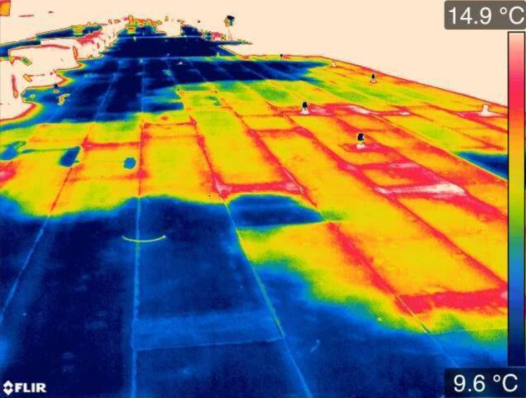


 Hot water on crack
 Cold water on crack
 Crack in a bridge
 Thermal view of bridge with no crack
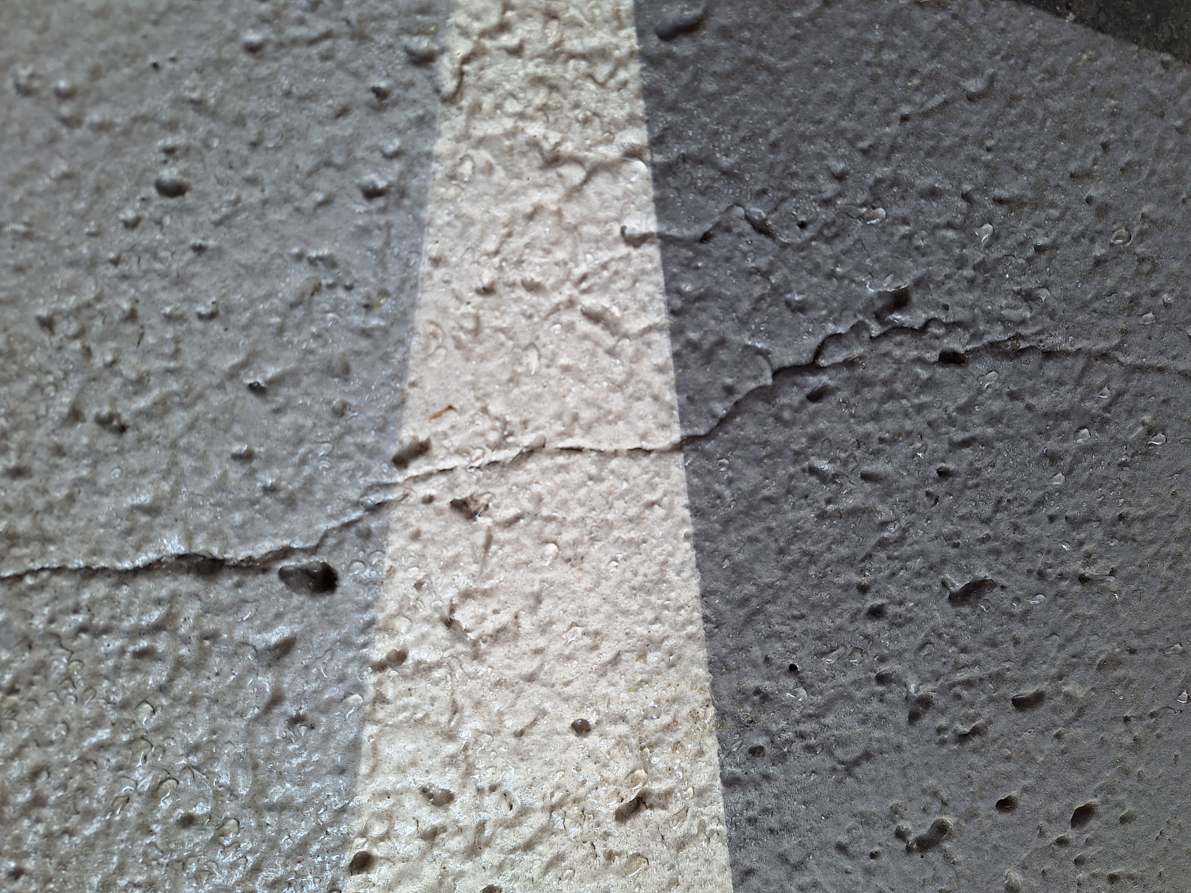 Crack in the bridge


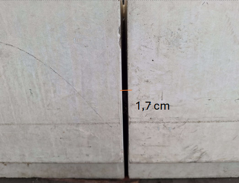 Concrete structure with gap
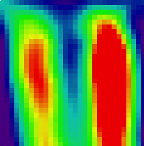 Thermal camera results
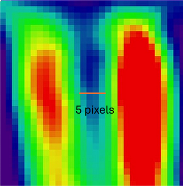 Thermal camera results with guideline

