Embedded Motion Control 2014 Group 8: Difference between revisions
Jump to navigation
Jump to search
No edit summary |
|||
| (25 intermediate revisions by 4 users not shown) | |||
| Line 40: | Line 40: | ||
</TABLE> | </TABLE> | ||
== PICO | == PICO information == | ||
[[File:PICO.png| 200px | 200px | right]] | [[File:PICO.png| 200px | 200px | right]] | ||
| Line 47: | Line 47: | ||
2. approximately 250 degrees of measurement direction <br> | 2. approximately 250 degrees of measurement direction <br> | ||
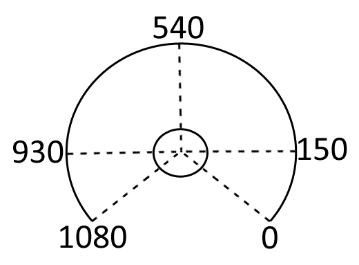
3. The datapoint at the left (930), front (540) and right (150) <br> | 3. The datapoint at the left (930), front (540) and right (150) <br> | ||
4 | 4. PICO's input for the velocity and angular velocity are in respectively m/s and rad/s.<br> | ||
<br> The figure on the right shows the location of the laser (distance) measurement points | <br> The figure on the right shows the location of the laser (distance) measurement points | ||
== | == Project structure == | ||
Below, the structure of the program is explained. | |||
=== Master === | === Master === | ||
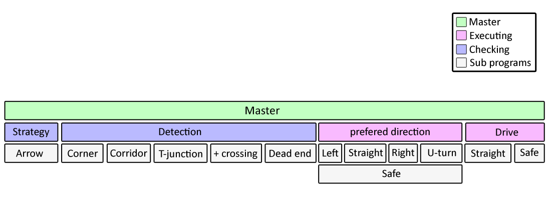
The Master file is the file which is taking control over everything that happens. Within the master file, there are the | The Master file is the file which is taking control over everything that happens. Within the master file, there are the options that should be checked and actions that should be performed. The checking action "Detection" is constantly sending (with a frequency of 20 Hz) information to the master. The information which is sent is whether there is; nothing special, a corner, a corridor, a T-junction, a plus-crossing or a dead end.<br> | ||
The | The decision action "Strategy" is receiving information from the master. This information is about whether something is detected or not and what is detected (by "Detection"). Then within "Strategy" it is determined whether there is an arrow or not. With this information, a desired direction is replied to the master.<br> | ||
Next to the checking sub files there are two executers. Note that either one of both can be executed. The drive block is called when "Strategy" does not give any input to the master. When "Strategy" does however, "Prefered turn" is the | Next to the checking sub files there are two executers. Note that either one of both can be executed. The drive block is called when "Strategy" does not give any input to the master. When "Strategy" does however, "Prefered turn" is the action to be executed.<br><br> | ||
The figure below gives a visual representation of the interaction within the system.<br> | The figure below gives a visual representation of the interaction within the system.<br> | ||
[[File:gr08_scheme.png| 450px| 900px | center | overview]] | [[File:gr08_scheme.png| 450px| 900px | center | overview]] | ||
| Line 89: | Line 85: | ||
In the first two cases, the robot drives backwards and turns to the right (in the first case) or to the left (in the second). In the second two cases the robot keeps driving but steers to the right (in the third case) or to the left (fourth case). | In the first two cases, the robot drives backwards and turns to the right (in the first case) or to the left (in the second). In the second two cases the robot keeps driving but steers to the right (in the third case) or to the left (fourth case). | ||
=== | === Corner detection === | ||
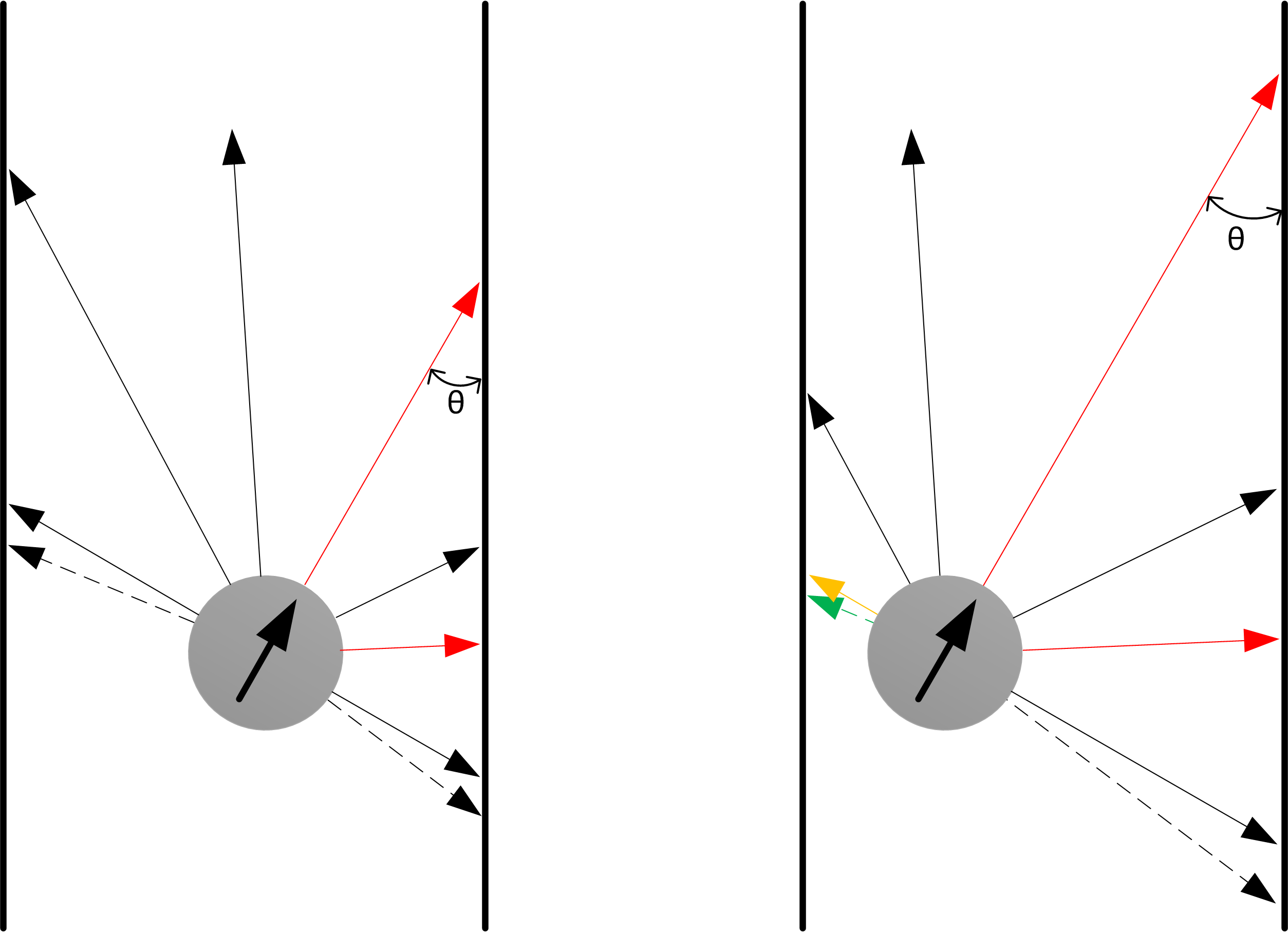
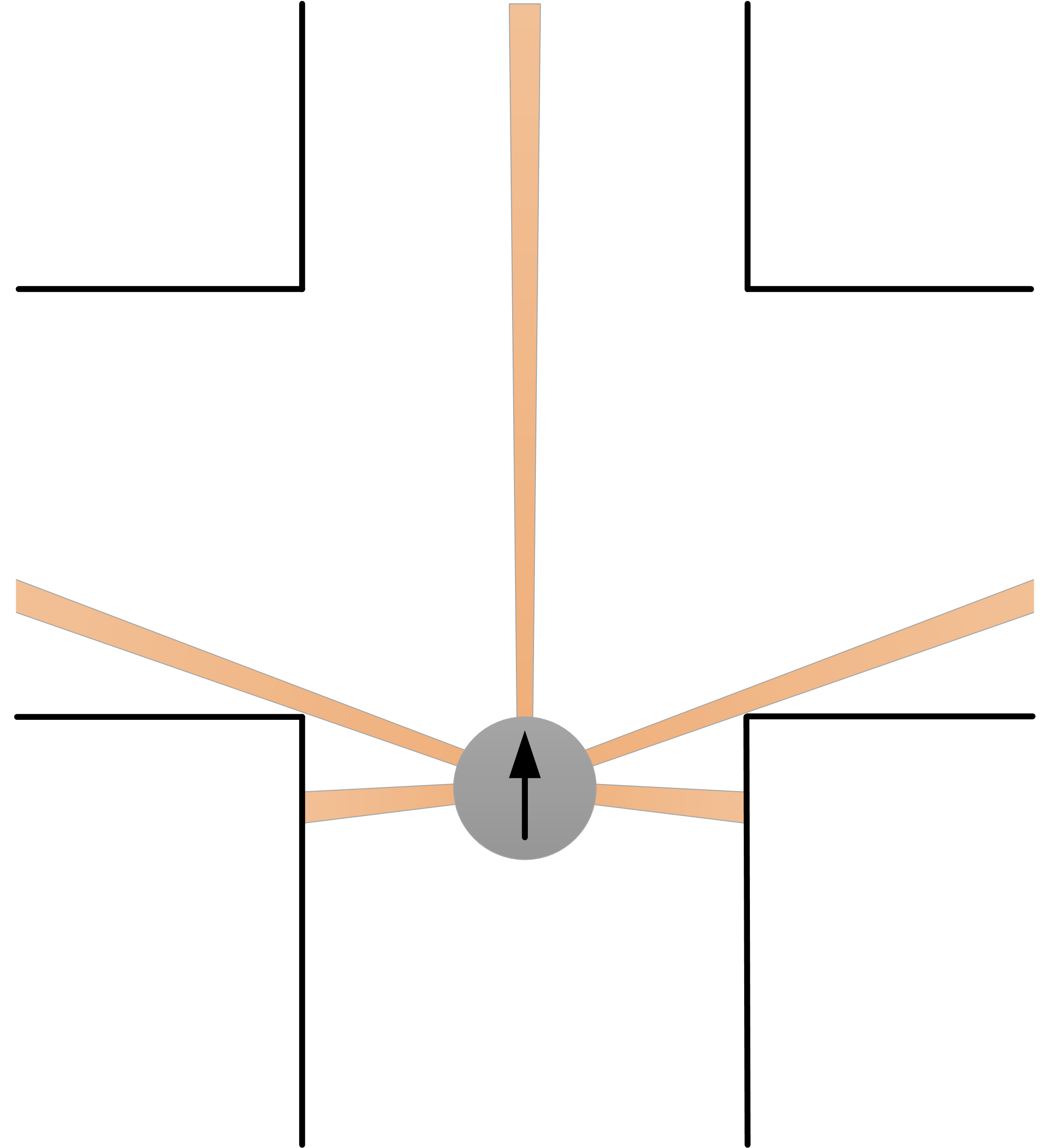
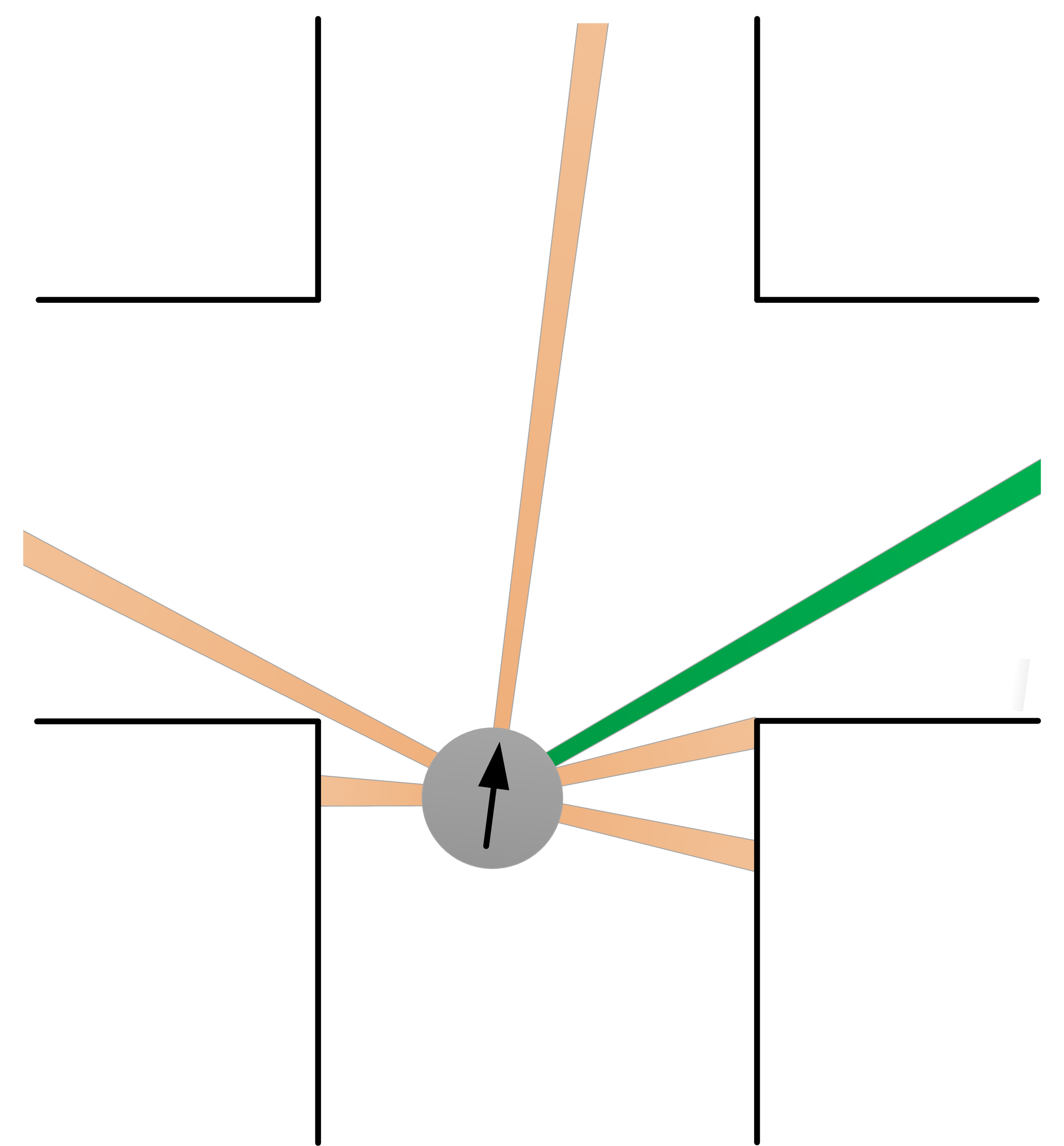
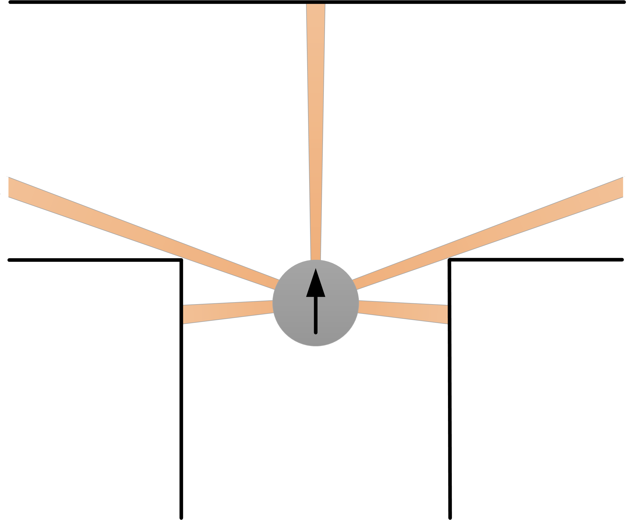
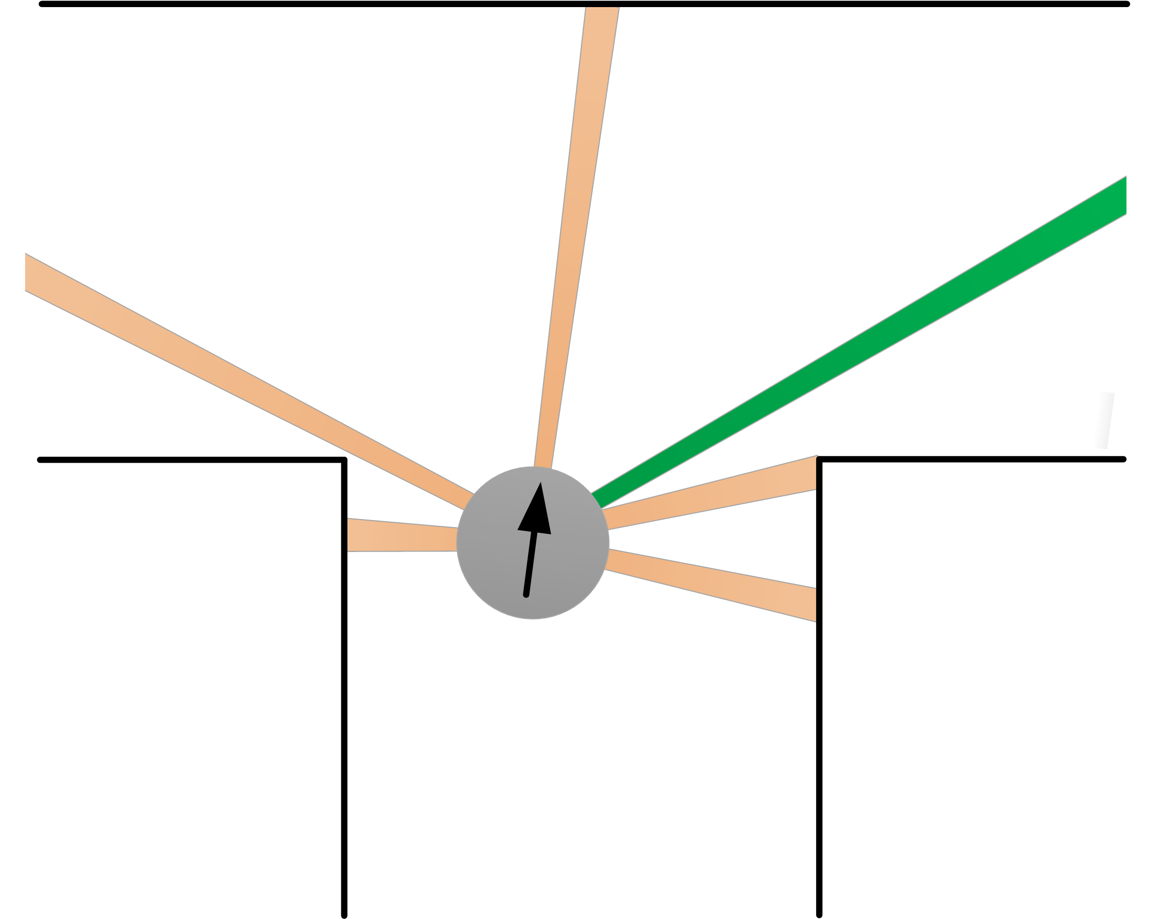
The differences between several laser points are used to detect | The differences between several laser points are used to detect openings. On both sides five laser points diagonally to the front and diagonally to the rear are used, as well as five laser points straight ahead. When the difference between all the askew frontal and rear points are larger than some threshold, an opening is detected. Note that five laser points are used for robustness. If one or two laser points would go through a hole in the wall, no opening should be detected. The difference between the two points is taken in order to use relative distances instead of absolute ones. Otherwise a new corner could be detected whenever a distance is large, for example in a large open field.<br><br> | ||
If an opening is detected there are four possible situations:<br> | |||
Note that five laser points | <ol> | ||
The difference between the two points is taken | <li>There is a crossing;</li> | ||
<br> | <li>There is a T-junction;</li> | ||
<li>There is an exit into a new corridor;</li> | |||
< | <li>There is a single corner.</li> | ||
</ol> | |||
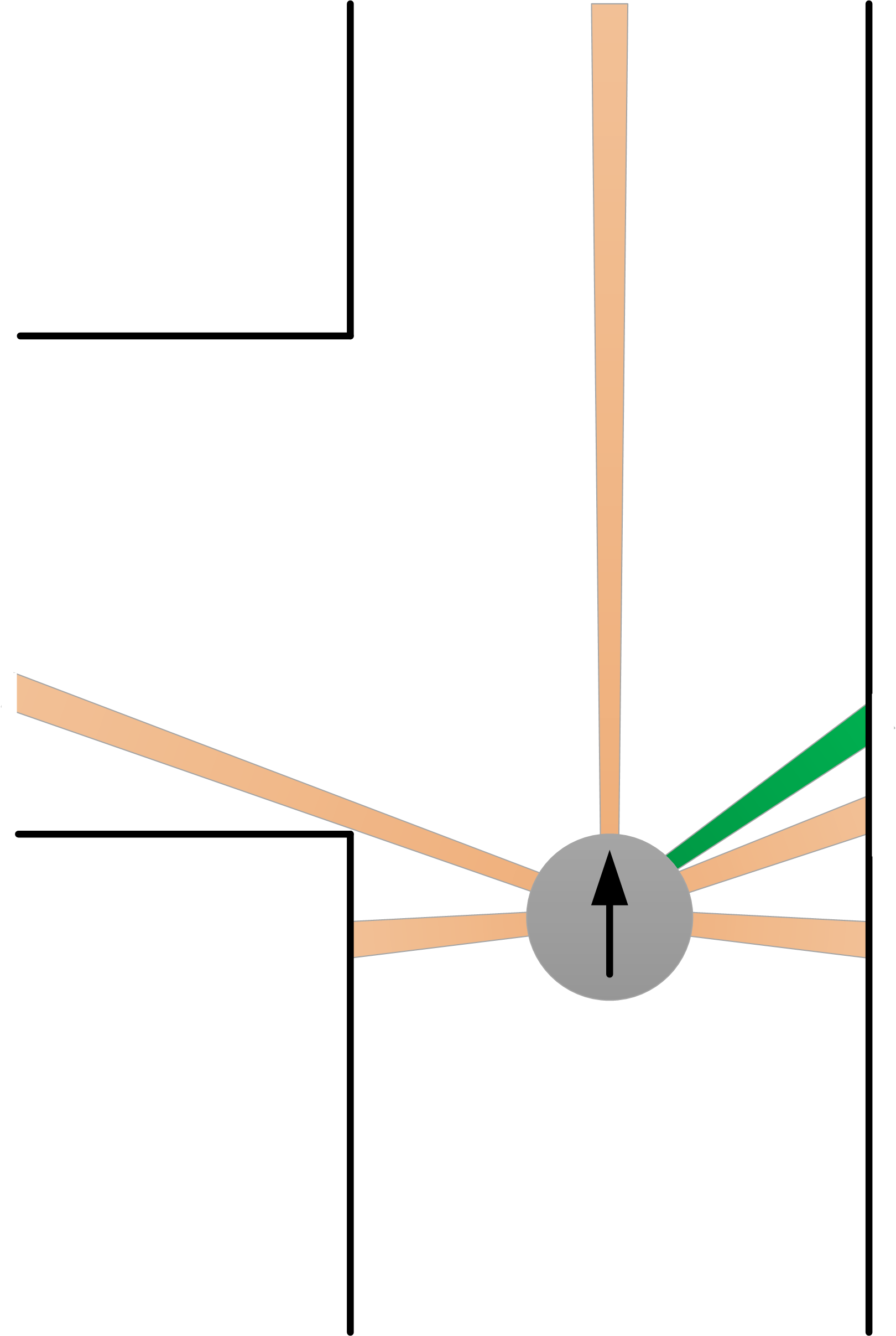
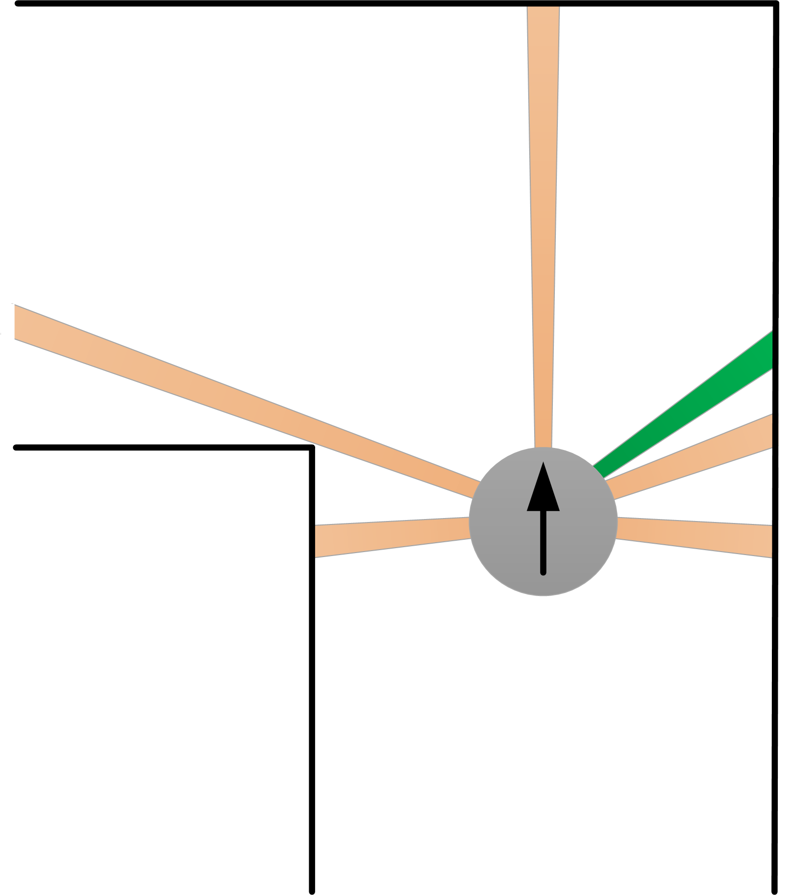
Ideally a crossing is detected as in the left figure below: at both sides an opening is detected as well as the opening straight ahead. However, if PICO arrives in a direction not exactly parallel to the wall one side opening is detected first, as will be the case in practical situations. Therefore, if a side opening is detected, a new set of laser point (the green area in the right figure below) checks for an opening at the other side too. If so, a crossing is found.<br><br> | |||
[[File:GR08_Pico_detect_crossing.png | 400px| 300px ]] | |||
[[File:GR08_Pico_detect_crossing_schuin.png | 400px| 300px ]] | |||
<br>The same is done for the T-junction, with the only difference there is not an opening straight ahead. Again the ideal situation (left figure below) will never occur, so an extra set of laser points is needed. See the figures below.<br><br> | |||
<!--[[File:detect_T-junc_1.png|550px|400px]]--> | <!--[[File:detect_T-junc_1.png|550px|400px]]--> | ||
<!--[[File:detect_T-junc_2.png|550px|400px]]--> | <!--[[File:detect_T-junc_2.png|550px|400px]]--> | ||
[[File:GR08_Pico_detect_Tjunc.png | 400px| 300px ]] | [[File:GR08_Pico_detect_Tjunc.png | 400px| 300px ]] | ||
[[File:GR08_Pico_detect_Tjunc_schuin.png | 400px| 300px ]] | [[File:GR08_Pico_detect_Tjunc_schuin.png | 400px| 300px ]] | ||
<br>If a side opening is detected and the extra set of laser points (the green ones) don’t detect another side opening, there are two possibilities left: an exit into a new corridor or just a corner, dependent of whether or not an opening is detected straight ahead. This is depicted in the two figures below.<br><br> | |||
[[File: | |||
[[File: | [[File:GR08_Pico_detect_corridor.png | 400px| 300px ]] | ||
[[File:GR08_Pico_detect_corner.png | 400px| 300px ]] | |||
<!--[[File:gr8_corner_detection.png | 550px| 400px | center]]--> | |||
<br>Finally it is checked whether a dead end is encountered. This is the case when no side opening is found and the set of lasers straight ahead return a value smaller than a threshold. This is also send back to the master file, so that a u-turn can be made instead of letting the drive safe modus inefficiently turn the PICO around. | |||
=== Strategy === | === Strategy === | ||
| Line 143: | Line 136: | ||
#Matching of the two types of arrows is compared. The one with most similarity to the arrow in the camera feed is chosen. | #Matching of the two types of arrows is compared. The one with most similarity to the arrow in the camera feed is chosen. | ||
#Depending on the result, either 0 (no arrow), 1 (left arrow) or 2 (right arrow) is being sent to the strategy of pico. | #Depending on the result, either 0 (no arrow), 1 (left arrow) or 2 (right arrow) is being sent to the strategy of pico. | ||
In the tests there was a problem. Arrows were detected at a too large distance from the arrow (see "Fourth test" on this wiki). This problem is solved by implementing two different sizes of arrows. The bigger template of the arrow is recognized if Pico is close to the arrow, the smaller if Pico is further away. Now at a way larger range an arrow can be detected. Also a history buffer that saves observed arrows for several iterations is added. This history buffer makes the algorithm more robust against "false positives". This was needed because false positives were detected. If in the last, for example, 6 iterations 5 arrows to the left, and 1 to the right are detected, it is possible the arrow to the right (the wrong arrow) is sent to the master node. After implementing the buffer, this problem was solved. | |||
=== Algorithm to solve the maze === | === Algorithm to solve the maze === | ||
| Line 181: | Line 176: | ||
=== Corridor test [16/05/2014] === | === Corridor test [16/05/2014] === | ||
Unfortunately there was not enough time to implement the observations in the code. The second method is used and | Unfortunately there was not enough time to implement the observations in the code. The second method is used and the corridor was passed in 32 seconds. | ||
=== second test [21/05/2014] === | === second test [21/05/2014] === | ||
| Line 190: | Line 185: | ||
=== Third test [05/06/2014] === | === Third test [05/06/2014] === | ||
After a new strategy for driving straight was proposed, this was tested on the setup. The new PD controller worked properly after being tuned. Also the new method for taking corners and ensuring safety while doing so was tested with satisfying results. Thereafter the u-turn was tested and tuned however this yielded a problem. After turning 180 degrees the PICO can stand under an angle with respect to the wall. When there is a short distance to the next (T-)crossing there may not be enough time to counteract this. When PICO is still not nearly parallel to the wall at this time an opening can be missed, this could send PICO in the wrong direction. | |||
=== Fourth test [12/06/2014]=== | |||
Here we started to test the arrow detection in real life. We ran into some problems regarding its robustness, the arrows were not always recognized. Thereby, if the were recognized, it was at a too large distance. By the time the Master node requested the arrow direction it was not detected any more. | |||
=== Fifth test [19/06/2014]=== | |||
Here we fine tuned some thresholds for the arrow detection. In the previous test we only looked for the color red on one side of the spectrum. When this was altered the arrow detection was robust. | |||
=== Sixth test [25/06/2014]=== | |||
In the final test we fine tuned the thresholds for the situation recognition. Resulting in a robuster detection of corners, crossings, dead ends, etc. | |||
=== | === Maze challenge === | ||
Finally, the real maze challenge. The goal; drive as fast as possible through the maze. <br> | |||
Expectations before seeing the maze;<br> | |||
* Due to the controller PICO should be able to drive nicely straight. <br> | |||
* The template matching worked very good during the last test sessions, hence we are expected to see all arrows. <br> | |||
* We take corners by cutting them instead of 90 degrees corners. This should give us some time advantage against other groups. <br> | |||
* We can solve any type of maze but due to the 'always turn right' algorithm, pico will most likely not take the most efficient way. <br><br> | |||
When we arrived at the challenge, we saw the maze. Yes, we will solve it. But unfortunately the first crossing will not be taken efficiently. The corridors are too large to detect dead ends before driving in there. <br> | |||
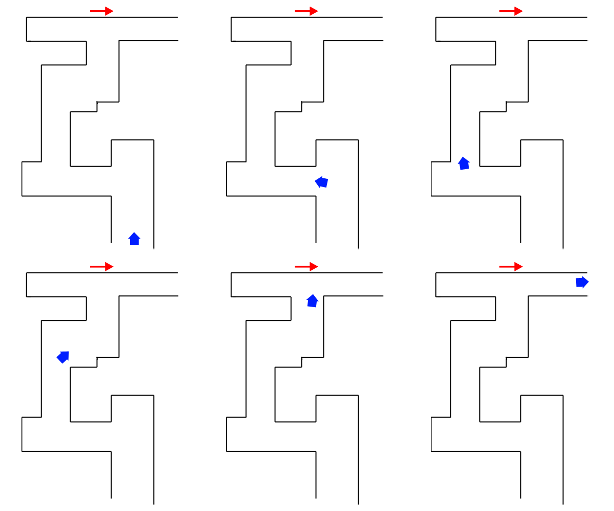
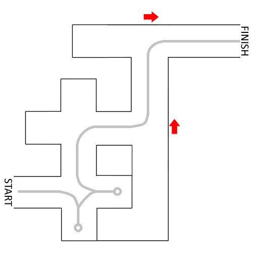
And indeed, all of our expectations were met. The maze was solved as shown in the figure below, in a time of 1'23. <br> | |||
[[File:challenge_08.png|center]] <br><br> | |||
Review on this challenge;<br> | |||
''Positives''<br> | |||
1. No other group was able to drive Pico as straight through the corridors as we did.<br> | |||
2. Our turns were very fast and efficient. <br> | |||
3. All arrows have been detected properly. <br> | |||
4. U-turn went perfect when the dead end was detected, and Pico came out of it straight due to the controller. <br> | |||
5. Every corner, T-junction and crossing have been detected. <br> | |||
6. Pico did not hit any wall. <br><br> | |||
''Shortcomings;''<br> | |||
1. We do not fit lines through the points. This also meant that we were not able to detect the dead end when the distance to the wall was larger than our treshold. Therefore we went into a wrong corner two times (algorithm of always turning right). | |||
<br><br> | |||
We would definately have been at the top 3, and have a very good chance on winning, if we would have implemented this. <br><br> | |||
On behalf of group 08; | |||
[[File:challenge_08_support.jpg|center]] | |||
== C++ coding == | == C++ coding == | ||
