Embedded Motion Control 2014 Group 9: Difference between revisions
| (111 intermediate revisions by 5 users not shown) | |||
| Line 1: | Line 1: | ||
=Team members= | |||
<table style="width: 100%;"> | <table style="width: 100%;"> | ||
<tr> | <tr> | ||
| Line 42: | Line 42: | ||
<br><br> | <br><br> | ||
=Planning= | |||
'''Week 1''' | '''Week 1''' | ||
* Installing Ubuntu | * Installing Ubuntu | ||
| Line 66: | Line 66: | ||
* Start writing arrow detection algorithm (Jordi/Jasper) | * Start writing arrow detection algorithm (Jordi/Jasper) | ||
* Measure laser distances during pico test | * Measure laser distances during pico test | ||
<br> | |||
---- | |||
<br><br> | |||
=Corridor competition= | |||
The code written for the corridor competition was written and tested. Even though the code functioned very well in the simulator, it did not function on the real pico. Corridors on the left were taken without problems but right corners were ignored. Pico detected the right corridors well, and also took the decision to turn right. However the right turn command was not executed properly. After reordering the code, the right turns were taken fine. | |||
== | ==Simple parallel wall driving== | ||
[[File:Pico simple drive parallel wall.png|thumb|center|200px]] A simple way is implemented to drive parallel next to the wall. | |||
The distance to the wall is measured in at an angle of 45deg left (a) and right (b). If the distance become below a threshold than pico will rotate in opposite direction as long as there is the wall (or other obstacle) within it's range. | |||
==Simple corner (corridor) detect== | |||
[[File:Pico simple corridor detect.png|thumb|center|200px]] A simple corner (corridor) detect is impmlemented in a seperate function. On the left and right side side corridors are detected by scanning an angle of -95 -> -85 and 85 -> 95 of pico. If 95% or more laserdata points within a range is higher than a treashold, than a corridor is detected. A detected corridor, left and/or right, is send a boolean the the navigation script as a return value. | |||
<br> | |||
==Script overview for corridor competition== | |||
The strategy for the corridor competition is quite simple. Pico will start drive trough the corridor keeping straight using the parallel wall driving. Once a corridor is detected pico will start rotating open loop wile keeping a forward velocity for a fixed amount of time. In this way a approximately 90 degree turn with a small radius is made. After the turn is complete pico will resume driving straight until it detects that is has no more walls around him and stop, assuming that it is finished. | |||
<br> | |||
---- | ---- | ||
<br><br> | |||
=Maze competition= | |||
== General info == | |||
The goal of the project is to find the exit of a maze autonomously by a robot. | |||
Of course there were some rules: | |||
* maximum translational velocity: 0.2 m/s (combined) | |||
* maximum rotational velocity: 1.0 rad/s | |||
* red Arrow(s) indicates direction | |||
* 2 attempts | |||
* maximum total time of 7 minutes | |||
A team will be disqualified if: | |||
* bumping into a wall | |||
* standing still for more than 30 seconds | |||
== Approach == | |||
The idea is to create a wall follower with some smart sensor triggered advantages to save time. | |||
These advantages are: | |||
* detecting dead ends in/of a corridor | |||
* detecting the red arrows. | |||
The final approuch is shown in the figure below: | |||
[[File:Maze_wf_de_ar.png|thumb|center|400px]] | |||
In this figure you can see clearly the skipped dead end in the lower left corner, the upper left corner and the upper right corner. Furthermore the response to a red Arrow is indicated. Finally can be concluded that this would be indeed the fastest way to the exit of the maze. | |||
== Implementation == | |||
As written in the section above, dead ends and arrows should be detected. But next to it, of course, the corridors should be detected. Without detecting corridors, Pico can't take a turn. | |||
We started with designing the proper framework for the different Ros Nodes and Ros Messages. Each node has a specific function and a predefined interface. An appropriate appropriate overview is found in the figure below: | |||
[[File:Overview.png|thumb|center|400px]] | |||
In this figure all hardware parts are coloured orange and all software nodes are coloured blue. | |||
We get the sonsor data from 2 sensors: the ''laser'' and the ''camera''. The laser data is send to the ''dead end'' and ''corridor'' nodes to detect dead ends in/of a corridor and to detected the corridors. The camera data is send to the 'arrow' node to do the image processing on it and detect a red arrow in the visual field of Pico. | |||
--- | The output of the three sensor processing nodes are send as a data stream to the ''navigation'' node. This node will contain an algorithm to drive through the maze, depending on its sensor inputs. Navigation will output the action that has to be done. | ||
This action will be received by the ''drive'' node. If, for example, a 'take turn left' is send, the drive node will control the hardware of ''Pico'' to do indeed a turn to the left. | |||
In total five nodes will be made. Further detailed description of each node are explained in the coming up sections. | |||
=== Dead end === | |||
<center> | |||
<gallery widths="250px" heights="240px" mode=packed> | |||
File:dead_end_right_1.png | |||
File:dead_end_right_2.png | |||
File:dead_end_right_3.png | |||
</gallery> | |||
</center> | |||
A dead end can be determined by detecting a step in the laser data distance. A step means that the distance is not continuously changing, but has a large difference between two data points. This large difference could be a possible corridor. | |||
In practice, the field of view of Pico is first divided in to three sections (left, right and straight). These are also the three possible directions in which Pico can move. If there is opening in one of these sections, so no dead end, this will show up as such a step in the laser data. | |||
In the above example there is a wall on the left, a dead end in front and a step in distance in the right section, so left and straight are recognized as a dead end. The node will now send a message ''dead end (left, right, straight) = [true, false, true]''. | |||
=== Corridor === | |||
<center> | |||
<gallery widths="250px" heights="240px"> | |||
File:corridor_1.png | |||
File:corridor_2.png | |||
File:corridor_3.png | |||
</gallery> | |||
</center> | |||
A corridor is detected by looking for a local minimum in the laser data. If such a local minimum is found, this indicates that there’s a corner in the wall, which could be corridor. | |||
The angle at which these local minimum should be, would be preferred at 135 deg. In that case Pico would stand in the middle of corridor and has a perfect view into that corridor, which is important for the dead end detect. Unfortunately the angle is 'only' ±127 deg. Nevertheless, this is large enough to let dead end work fine. | |||
But now, when Pico is driving, the corridor node looks to both ends of the laser data (the -127 and +127 deg). These outer ranges of the laser are divided in three sections. If now the center section has a smaller averaged distance than the section to the left and right, a local minimum is detected. | |||
To make sure that there is indeed a corridor Pico also checks the distance besides him to see if there’s really an opening in the wall. This avoids detecting a corridor when there is only an edge due to for example an irregularity in the wall. The node will now send a message ''corridor (left, right) = [false, true]. | |||
=== Arrow === | |||
The Arrow node processes the camera date to look for an arrow in the image, and if there is an arrow, in which direction it is turning. This information is also send to the navigation node. This node uses the opencv library. <BR> | |||
The arrow detection first crops the RGB image so that possible disturbances outside the maze are not taken into account. The RGB image will be converted to an HSV image, where the hue, saturation and variation play an important roll to make sure only the red colour is selected.The HSV image will then be converted into a binary image, which is then blurred to decrease disturbances. <BR> | |||
<center> | |||
<gallery widths="250px" heights="240px" mode=packed> | |||
File:RGB_image.png | |||
File:HSV_threshold_image.png | |||
</gallery> | |||
</center> | |||
<BR><BR> | |||
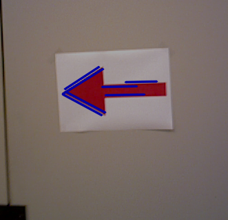
In this blurred image it is looked for how long white pixels are connected with each other. When they have a minimal length of and x-amount of pixels and are not interrupted by more than a x-amount of black pixels, a line is created. Lines with an angle between 20 and 60 degree are filtered, since these lines are created at the head of the arrow and indicate if the arrow is pointing left or right. By checking the slope of each line (negative or positive) and check whether lines with a positive slope are below or above the lines with a negative slope, it can be seen if the arrow is pointing right or left. If the lines with a positive slope are above the lines with a negative slope, then the arrow is pointing to the left, visa versa, the arrow is pointing to the right. | |||
<BR> | |||
[[File:lines_image.png|thumb|center|600px]]<BR> | |||
A counter is added to add robustness to the arrow detection. For every frame it detects an arrow (where it makes a distinction between left and right) a value of 5 is added to the counter, and for every frame it does not see an arrow, a value of 1 is subtracted from the counter. If the counter exceeds the value 16 it states that it indeed sees an arrow. A boolean is stated true for the left or right arrow and is sent to the navigation script, where it has first priority. | |||
[[File:arrow_counter.png|thumb|center|3000px]]<BR> | |||
<br><br> | |||
=== Navigation === | |||
The Navigation node determine the direction in which to drive to. To make a decision based on the data from the Dead end, Corridor, and Arrow node. It is a rule based navigation based on the principal to always go left. In this case the exit of the maze is always found. If there is a possibility to go left it always will go left unless it is overruled by a right pointing arrow. If it can go straight and right it will always go straight. If the only option is right it will go right. And if all the three directions are a dead end if will turn 180 degrees. These rules are shown in the flowchart below. | |||
[[File:Nav_flowchart.png|thumb|center|600px]] | |||
<br><br> | |||
=== Drive === | |||
The Drive node will execute the commands given by the Navigation node. The default option is to drive straight, other options are to make a turn to either left of right, or to turn around in case of a dead end. | |||
For the functionalities of the drive node a few other functions are used, which are explained below. | |||
''' Line and middle detection ''' | |||
The functions are specified in three different functions: | |||
''' Scanxy (brown lines) ''' | |||
This function reviews the laserdata and tranlates them to a structure with their x and y distance with respect to pico. | |||
''' linedetect ''' | |||
input: (Sxy xy,double x1, double x2, double y1, double y2, double angle, double Tol, int conf) | |||
Here the square where the function searched within is defined bij x1<x<x2 and y1<y<y2, by the user, and so is the desired search angle with certain tolerance angle and confidence. This program can be used to find angles of certain lines in a domain. But it can also be used to determine if there is any. | |||
<center> | |||
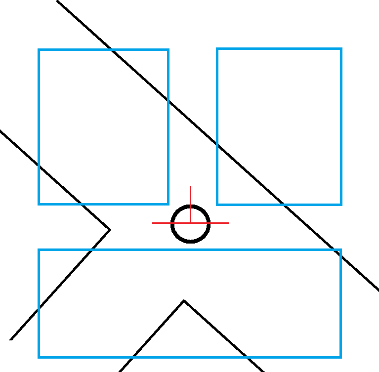
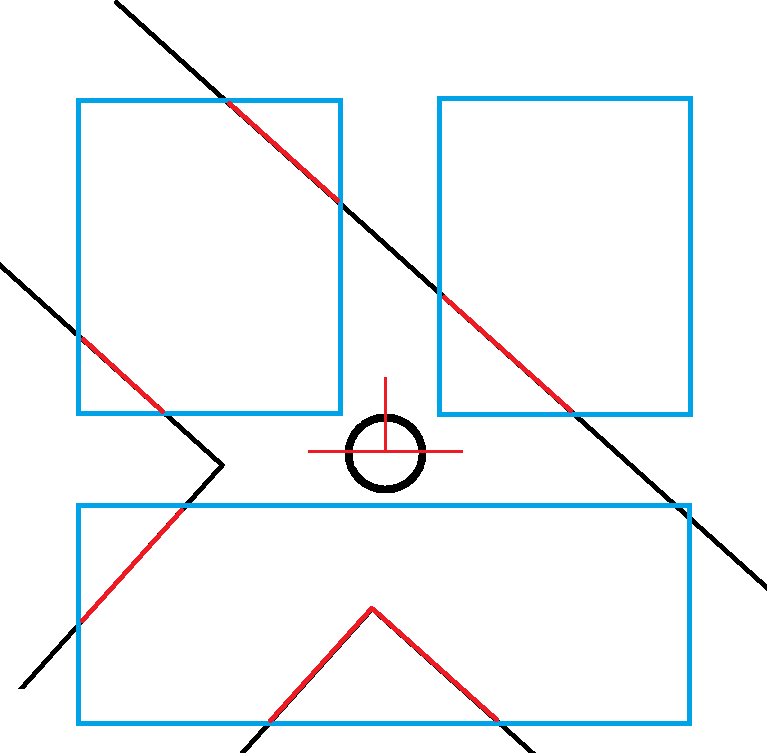
[[File:Scan straight.png|thumb|center|1000px]] For the detection of the world and the desired direction, two scripts have been implemented. These two are visualised in the figure. | |||
</center> | |||
''OLD version: Straightdetect; (other lines) | |||
This function uses the result of scanxy, a struct of type Sxy of x and y coordinates. It analyzes the direction of the corridor with respect to the orientation of pico. It does this by looking at 2 laser points and comparing the dx and dy to calculate an angle. For robustness this process is repeated for multiple pairs of dots, the results are filtered and averaged. This results in a good and robust measurement of the angle which pico could rotate to be located straight in the corridor.'' | |||
''' Middledetect ''' | |||
Middledetect uses the structure Sxy xy to determine the middle of the hallway. It returns the distance in which it could drive to find the middle of the corridor, but does not steer of the wall for more than 0.75m | |||
Method: determine average of left and right points. (with maximal distance of 0.75m) Then subtract to find the difference between the two. Note that the box with the points and the maximal value 0.75 are also input of the function. | |||
==== Straight driving ==== | |||
For straight driving the forward speed is set to the maximum. Pico should then rotate towards the straight, at the same time pico should correct to find the center of the corridor. | |||
'''Y-axis;''' The centre is tracked by analyzing the distance towards the middle using middledetect. A simple and weak P controller is already enough to follow the middle of the corridor. | |||
'''Rotation;''' At the same time pico will try to find the angle of the corridor (using linedetect) and compensate for that, also with a simple weak P controller. In this case pico has two states, a high precision state where little tolerance is allowed, using lines at the straight or at a 90 degree rotation. If this high precision is not met, than a higher tolerance (-/+ 30 degrees) is allowed to find only the straight. In this case pico can also follow curved/.. walls and other strange situations. But then it is more sensitive to disturbances. | |||
to | |||
<center> | |||
High precision straight driving versus low precision straight driving | |||
<gallery widths="350px" heights="300px" mode=packed> | |||
File:drive5.png | |||
File:drive5 low precision.png | |||
</gallery> | |||
</center> | |||
==== Cornering ==== | |||
For cornering the linedetection is used again. As soon as drive receives the order it assumes the corner can be taken. The methods are nearly similar in a right or left rotation. | |||
Cornering is separated in two parts; the first 45 degrees, then the next 45-90 degrees rotation. Only after both parts are done, the cornering is finished and straight driving is continued. | |||
<center> | |||
Cornering; first 45 degrees | |||
<gallery widths="250px" heights="240px" mode=packed> | |||
File:drive6a.png | |||
File:drive7.png | |||
File:drive8.png | |||
</gallery> | |||
=== | Cornering; Next 45 to 90 degrees rotation | ||
<gallery widths="250px" heights="240px" mode=packed> | |||
File:drive9.png | |||
File:drive10.png | |||
File:drive11.png | |||
</gallery> | |||
</center> | |||
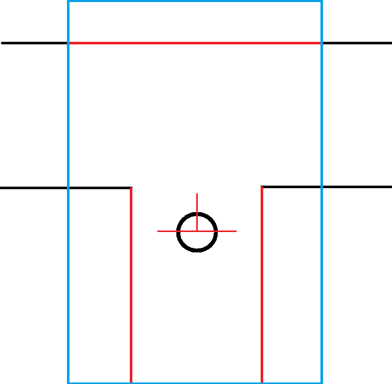
Pico starts rotating and determines appropriately when the first 45 degrees of the rotation is done. Different (blue) areas are chosen for robustness. If lines at +/- 45 degrees can be found, the first part of the rotation is done and the last part of rotation begins. | |||
This last part of the rotation is done as soon as a straight line is found again by linedetect, after which straigth driving is continued. During rotation drive does not listen to the navigation node untill it is done with the corner. | |||
==== | ==== dead end, turn around ==== | ||
In the case of a dead end pico turns in the opposite direction of the tactic, so clockwise. Pico turns for as long as dead end detection is true, and finds a straight afterwards. | |||
==== | ==== Safety ==== | ||
Next to all the other nodes, Pico could still run into problems. In this case pico searches for the most open direction and rotates towards it. For this is searches at a 45 degree angle. Should the safedrive go off, pico will rotate clockwise | |||
== | == Messages and Topics == | ||
All the nodes use different Topics and messages to communicate with each other as shown in the framework picture below. Below is an explanation of all the topics and messages. | |||
[[File:Framework2.png|thumb|center|600px]] | |||
To make it easy in creating and declerations, for all nodes the same massage type is used. Nevertheless, some values are ignored in some nodes. | |||
=== pico/dead_end === | |||
The Dead end node will publish it results on the pico/dead_end topic. To do this it uses a dead_end message with the following construction: | The Dead end node will publish it results on the pico/dead_end topic. To do this it uses a dead_end message with the following construction: | ||
* bool left | |||
* bool right | |||
* bool straight | |||
=== pico/corridor === | |||
The Corridor node will publish it results on the pico/corridor topic. To do this it uses a corridor message with the following construction: | The Corridor node will publish it results on the pico/corridor topic. To do this it uses a corridor message with the following construction: | ||
* bool left | |||
* bool right | |||
* bool straight (Note: straight will be ignored for this node.) | |||
=== pico/arrow === | |||
The Arrow node will publish it results on the pico/arrow topic. To do this it uses a arrow message with the following construction: | The Arrow node will publish it results on the pico/arrow topic. To do this it uses a arrow message with the following construction: | ||
* bool left | |||
* bool right | |||
* bool straight (Note: straight will be ignored for this node.) | |||
=== pico/direction === | |||
The Navigation node will publish it results on the pico/Direction topic. To do this it uses a direction message with the following construction: | The Navigation node will publish it results on the pico/Direction topic. To do this it uses a direction message with the following construction: | ||
* int direction<br><br> | |||
The value of this integer determines the direction as follows:<br><br> | The value of this integer determines the direction as follows:<br><br> | ||
* 1 = straight | |||
* 2 = left turn | |||
* 3 = right turn | |||
* 4 = 180 deg turn | |||
== | == Maze competition: The result == | ||
The maze was completed by our Pico in a time of 1 minute and 7 seconds. This result means we ended 4th out of 12. | |||
<BR> | |||
The advantage of our script is that every node has to run separately, while this may seem inconvenient, it quickens the start of Pico once the drive node is ran, since all the other nodes are already running. Where Pico stood still the first couple of seconds for other groups, ours already took of like a rocket at the start. Pico succesfully detected both arrows an therefor took the shortest way to the end of the maze. An improvement for the script is with taking corners, on this point we 'lost' the competition, since it was rather slow and not smooth in taking corners. | |||
<br> | |||
[[File:Youtube.png|link=https://www.youtube.com/watch?v=EEnnlxGfDIA]] | |||
=== Time Survey === | |||
https://www.dropbox.com/s/40z8zqg9a69aysr/Time%20survey%204K450.xlsx | |||
Latest revision as of 13:15, 3 July 2014
Team members
| Name | Student # | Remark | |
| Koos Elferink | k.elferink@student.tue.nl | 0716494 | |
| Joost Potma | j.potma@student.tue.nl | 0864146 | |
| Jasper Spanjaards | j.j.a.spanjaards@student.tue.nl | 0746039 | |
| Jordi van Dijk | j.v.dijk@student.tue.nl | 0805981 | |
| René Bruintjes | r.f.bruintjes@student.tue.nl | 0877139 |
Planning
Week 1
- Installing Ubuntu
- Installing ROS
- Installing SVN
- Follow tutorial C++
Week 2
- Install Qt-creator (IDE)
- Group meeting to make a start on the project
- Test robot with standard script
- Test robot with added self made script parts
Week 3
- Group meeting (goal: finish corridor script)
- Second test on robot (test script)
- Corridor contest (16 May)
Week 4
- Group meeting (goal: maze solving strategy)
- Function to make Pico drive straight through the maze. (Koos)
- Make proper software architecture with nodes/topics (Joost/René)
- Start writing arrow detection algorithm (Jordi/Jasper)
- Measure laser distances during pico test
Corridor competition
The code written for the corridor competition was written and tested. Even though the code functioned very well in the simulator, it did not function on the real pico. Corridors on the left were taken without problems but right corners were ignored. Pico detected the right corridors well, and also took the decision to turn right. However the right turn command was not executed properly. After reordering the code, the right turns were taken fine.
Simple parallel wall driving
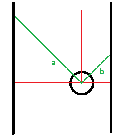
A simple way is implemented to drive parallel next to the wall.
The distance to the wall is measured in at an angle of 45deg left (a) and right (b). If the distance become below a threshold than pico will rotate in opposite direction as long as there is the wall (or other obstacle) within it's range.
Simple corner (corridor) detect
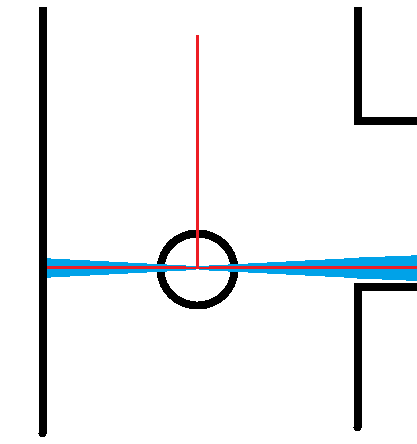
A simple corner (corridor) detect is impmlemented in a seperate function. On the left and right side side corridors are detected by scanning an angle of -95 -> -85 and 85 -> 95 of pico. If 95% or more laserdata points within a range is higher than a treashold, than a corridor is detected. A detected corridor, left and/or right, is send a boolean the the navigation script as a return value.
Script overview for corridor competition
The strategy for the corridor competition is quite simple. Pico will start drive trough the corridor keeping straight using the parallel wall driving. Once a corridor is detected pico will start rotating open loop wile keeping a forward velocity for a fixed amount of time. In this way a approximately 90 degree turn with a small radius is made. After the turn is complete pico will resume driving straight until it detects that is has no more walls around him and stop, assuming that it is finished.
Maze competition
General info
The goal of the project is to find the exit of a maze autonomously by a robot.
Of course there were some rules:
- maximum translational velocity: 0.2 m/s (combined)
- maximum rotational velocity: 1.0 rad/s
- red Arrow(s) indicates direction
- 2 attempts
- maximum total time of 7 minutes
A team will be disqualified if:
- bumping into a wall
- standing still for more than 30 seconds
Approach
The idea is to create a wall follower with some smart sensor triggered advantages to save time.
These advantages are:
- detecting dead ends in/of a corridor
- detecting the red arrows.
The final approuch is shown in the figure below:
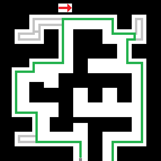
In this figure you can see clearly the skipped dead end in the lower left corner, the upper left corner and the upper right corner. Furthermore the response to a red Arrow is indicated. Finally can be concluded that this would be indeed the fastest way to the exit of the maze.
Implementation
As written in the section above, dead ends and arrows should be detected. But next to it, of course, the corridors should be detected. Without detecting corridors, Pico can't take a turn.
We started with designing the proper framework for the different Ros Nodes and Ros Messages. Each node has a specific function and a predefined interface. An appropriate appropriate overview is found in the figure below:

In this figure all hardware parts are coloured orange and all software nodes are coloured blue.
We get the sonsor data from 2 sensors: the laser and the camera. The laser data is send to the dead end and corridor nodes to detect dead ends in/of a corridor and to detected the corridors. The camera data is send to the 'arrow' node to do the image processing on it and detect a red arrow in the visual field of Pico.
The output of the three sensor processing nodes are send as a data stream to the navigation node. This node will contain an algorithm to drive through the maze, depending on its sensor inputs. Navigation will output the action that has to be done.
This action will be received by the drive node. If, for example, a 'take turn left' is send, the drive node will control the hardware of Pico to do indeed a turn to the left.
In total five nodes will be made. Further detailed description of each node are explained in the coming up sections.
Dead end
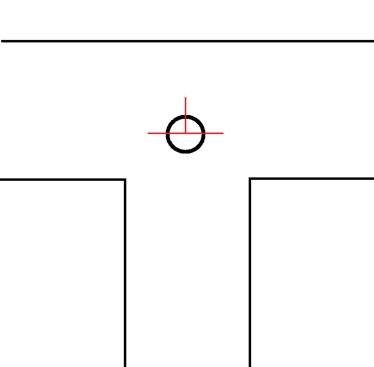
A dead end can be determined by detecting a step in the laser data distance. A step means that the distance is not continuously changing, but has a large difference between two data points. This large difference could be a possible corridor.
In practice, the field of view of Pico is first divided in to three sections (left, right and straight). These are also the three possible directions in which Pico can move. If there is opening in one of these sections, so no dead end, this will show up as such a step in the laser data.
In the above example there is a wall on the left, a dead end in front and a step in distance in the right section, so left and straight are recognized as a dead end. The node will now send a message dead end (left, right, straight) = [true, false, true].
Corridor
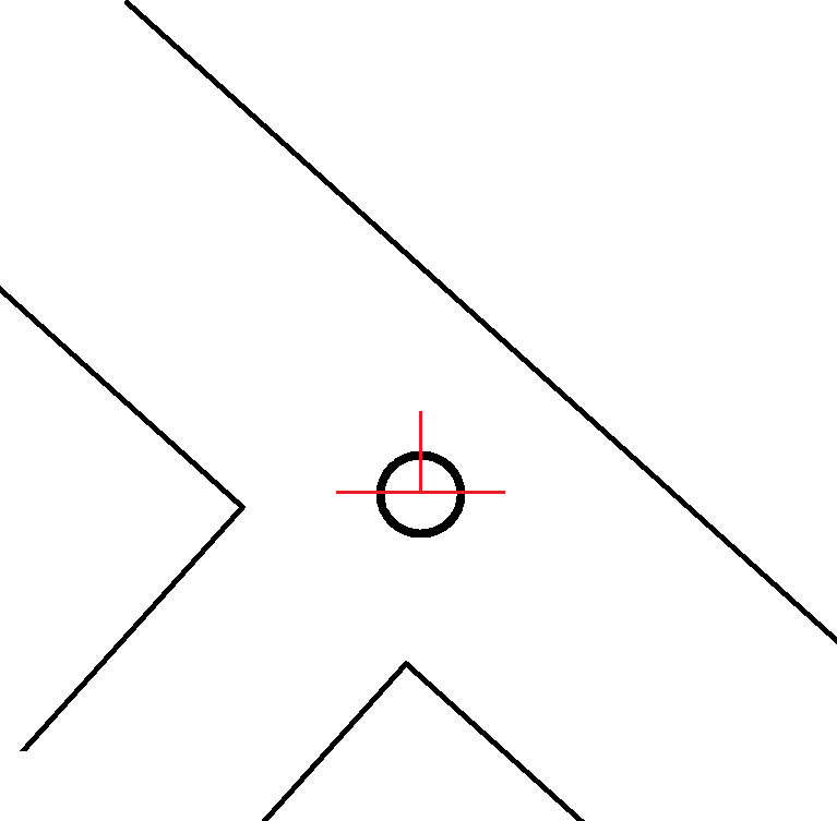
A corridor is detected by looking for a local minimum in the laser data. If such a local minimum is found, this indicates that there’s a corner in the wall, which could be corridor.
The angle at which these local minimum should be, would be preferred at 135 deg. In that case Pico would stand in the middle of corridor and has a perfect view into that corridor, which is important for the dead end detect. Unfortunately the angle is 'only' ±127 deg. Nevertheless, this is large enough to let dead end work fine.
But now, when Pico is driving, the corridor node looks to both ends of the laser data (the -127 and +127 deg). These outer ranges of the laser are divided in three sections. If now the center section has a smaller averaged distance than the section to the left and right, a local minimum is detected. To make sure that there is indeed a corridor Pico also checks the distance besides him to see if there’s really an opening in the wall. This avoids detecting a corridor when there is only an edge due to for example an irregularity in the wall. The node will now send a message corridor (left, right) = [false, true].
Arrow
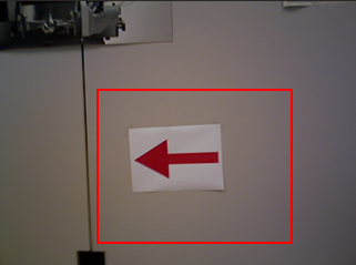
The Arrow node processes the camera date to look for an arrow in the image, and if there is an arrow, in which direction it is turning. This information is also send to the navigation node. This node uses the opencv library.
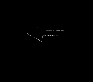
The arrow detection first crops the RGB image so that possible disturbances outside the maze are not taken into account. The RGB image will be converted to an HSV image, where the hue, saturation and variation play an important roll to make sure only the red colour is selected.The HSV image will then be converted into a binary image, which is then blurred to decrease disturbances.
In this blurred image it is looked for how long white pixels are connected with each other. When they have a minimal length of and x-amount of pixels and are not interrupted by more than a x-amount of black pixels, a line is created. Lines with an angle between 20 and 60 degree are filtered, since these lines are created at the head of the arrow and indicate if the arrow is pointing left or right. By checking the slope of each line (negative or positive) and check whether lines with a positive slope are below or above the lines with a negative slope, it can be seen if the arrow is pointing right or left. If the lines with a positive slope are above the lines with a negative slope, then the arrow is pointing to the left, visa versa, the arrow is pointing to the right.
A counter is added to add robustness to the arrow detection. For every frame it detects an arrow (where it makes a distinction between left and right) a value of 5 is added to the counter, and for every frame it does not see an arrow, a value of 1 is subtracted from the counter. If the counter exceeds the value 16 it states that it indeed sees an arrow. A boolean is stated true for the left or right arrow and is sent to the navigation script, where it has first priority.

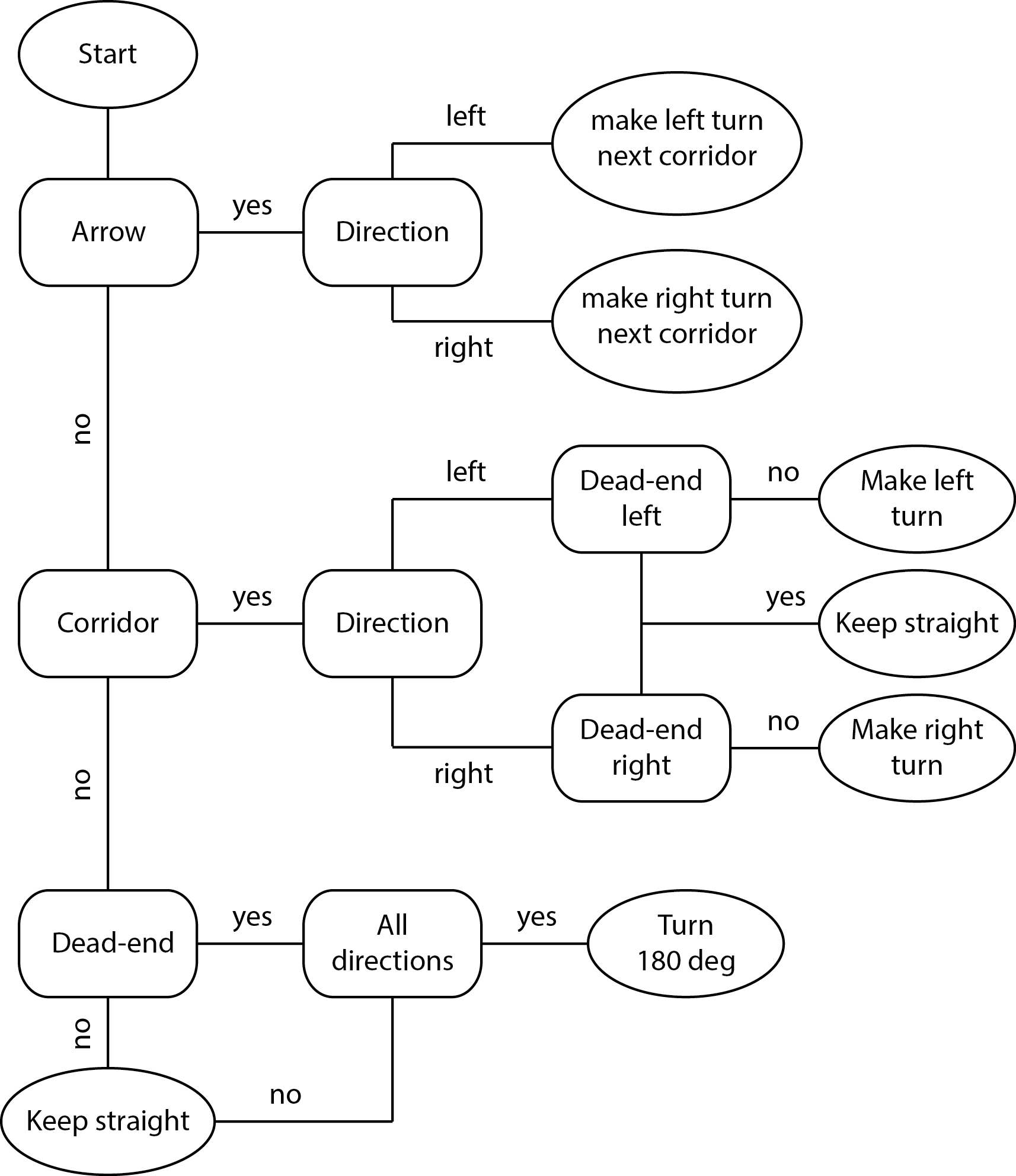
The Navigation node determine the direction in which to drive to. To make a decision based on the data from the Dead end, Corridor, and Arrow node. It is a rule based navigation based on the principal to always go left. In this case the exit of the maze is always found. If there is a possibility to go left it always will go left unless it is overruled by a right pointing arrow. If it can go straight and right it will always go straight. If the only option is right it will go right. And if all the three directions are a dead end if will turn 180 degrees. These rules are shown in the flowchart below.
Drive
The Drive node will execute the commands given by the Navigation node. The default option is to drive straight, other options are to make a turn to either left of right, or to turn around in case of a dead end.
For the functionalities of the drive node a few other functions are used, which are explained below.
Line and middle detection
The functions are specified in three different functions:
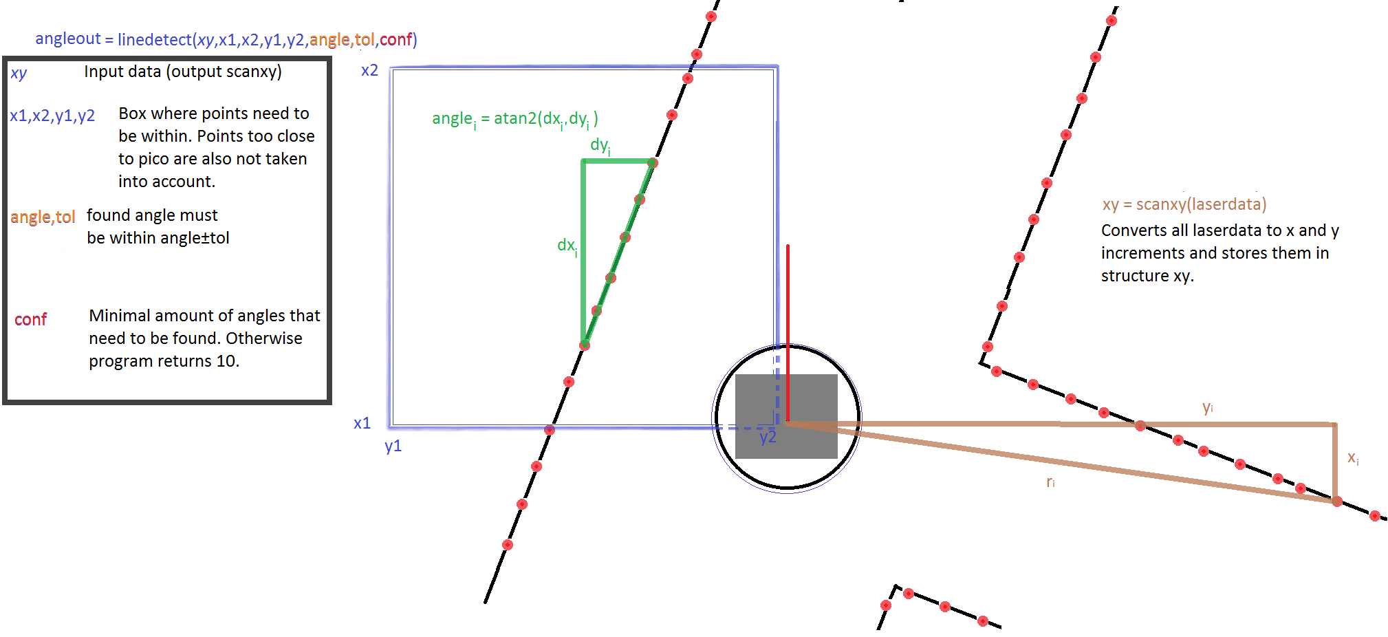
Scanxy (brown lines)
This function reviews the laserdata and tranlates them to a structure with their x and y distance with respect to pico.
linedetect
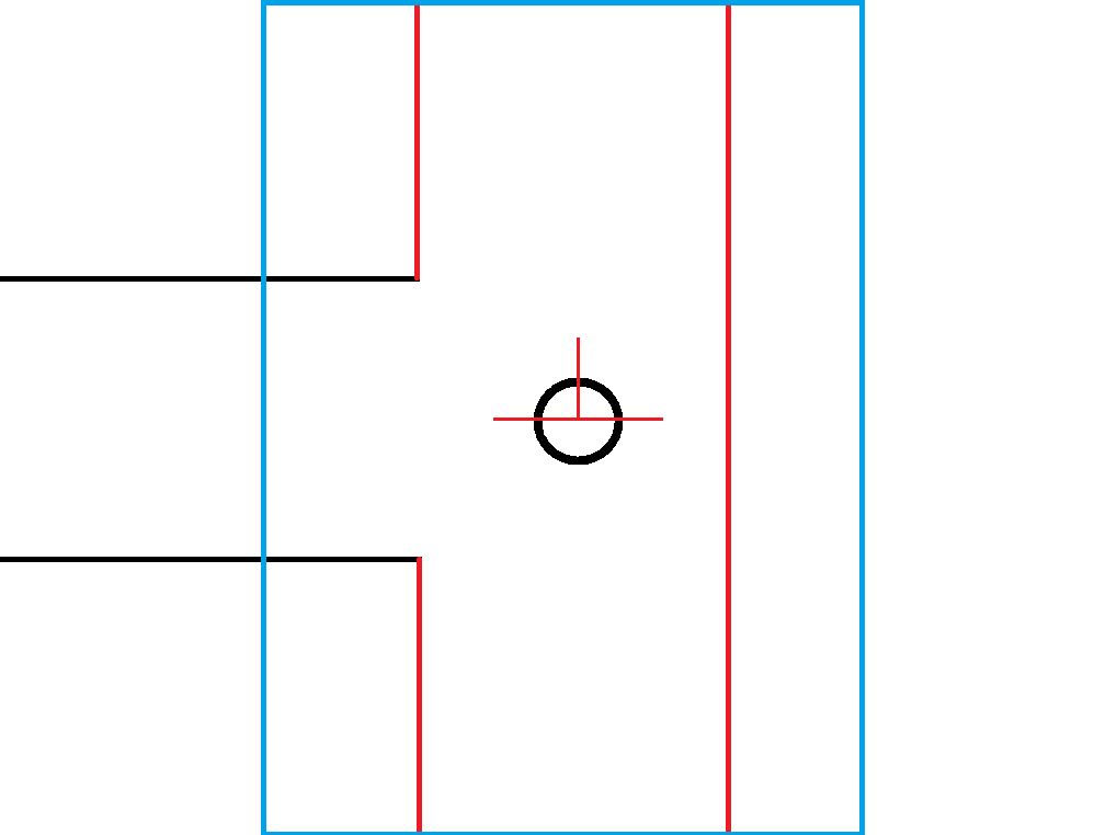
input: (Sxy xy,double x1, double x2, double y1, double y2, double angle, double Tol, int conf) Here the square where the function searched within is defined bij x1<x<x2 and y1<y<y2, by the user, and so is the desired search angle with certain tolerance angle and confidence. This program can be used to find angles of certain lines in a domain. But it can also be used to determine if there is any.
OLD version: Straightdetect; (other lines)
This function uses the result of scanxy, a struct of type Sxy of x and y coordinates. It analyzes the direction of the corridor with respect to the orientation of pico. It does this by looking at 2 laser points and comparing the dx and dy to calculate an angle. For robustness this process is repeated for multiple pairs of dots, the results are filtered and averaged. This results in a good and robust measurement of the angle which pico could rotate to be located straight in the corridor.
Middledetect
Middledetect uses the structure Sxy xy to determine the middle of the hallway. It returns the distance in which it could drive to find the middle of the corridor, but does not steer of the wall for more than 0.75m Method: determine average of left and right points. (with maximal distance of 0.75m) Then subtract to find the difference between the two. Note that the box with the points and the maximal value 0.75 are also input of the function.
Straight driving
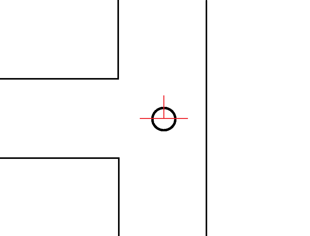
For straight driving the forward speed is set to the maximum. Pico should then rotate towards the straight, at the same time pico should correct to find the center of the corridor.
Y-axis; The centre is tracked by analyzing the distance towards the middle using middledetect. A simple and weak P controller is already enough to follow the middle of the corridor.
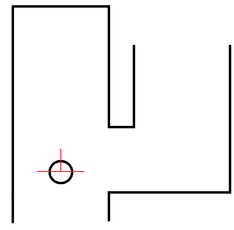
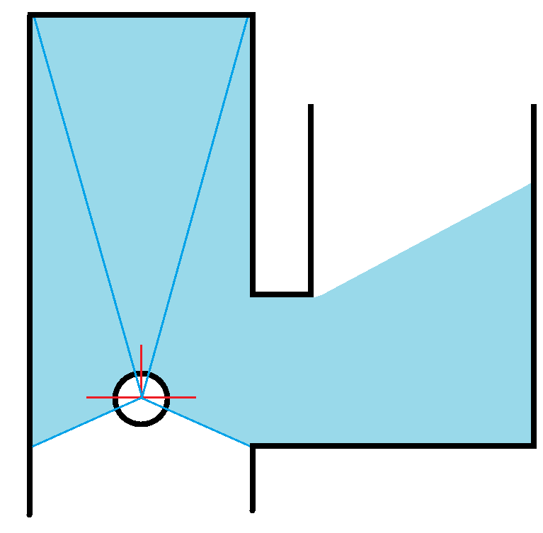
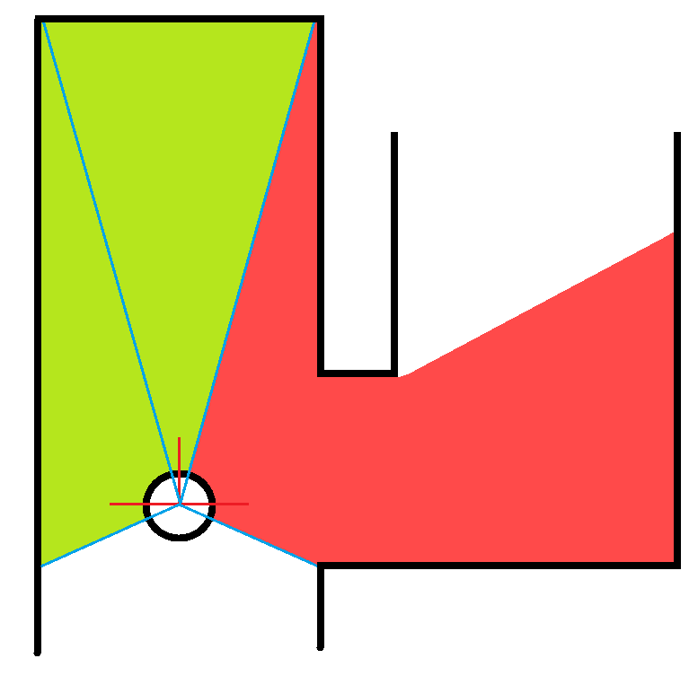
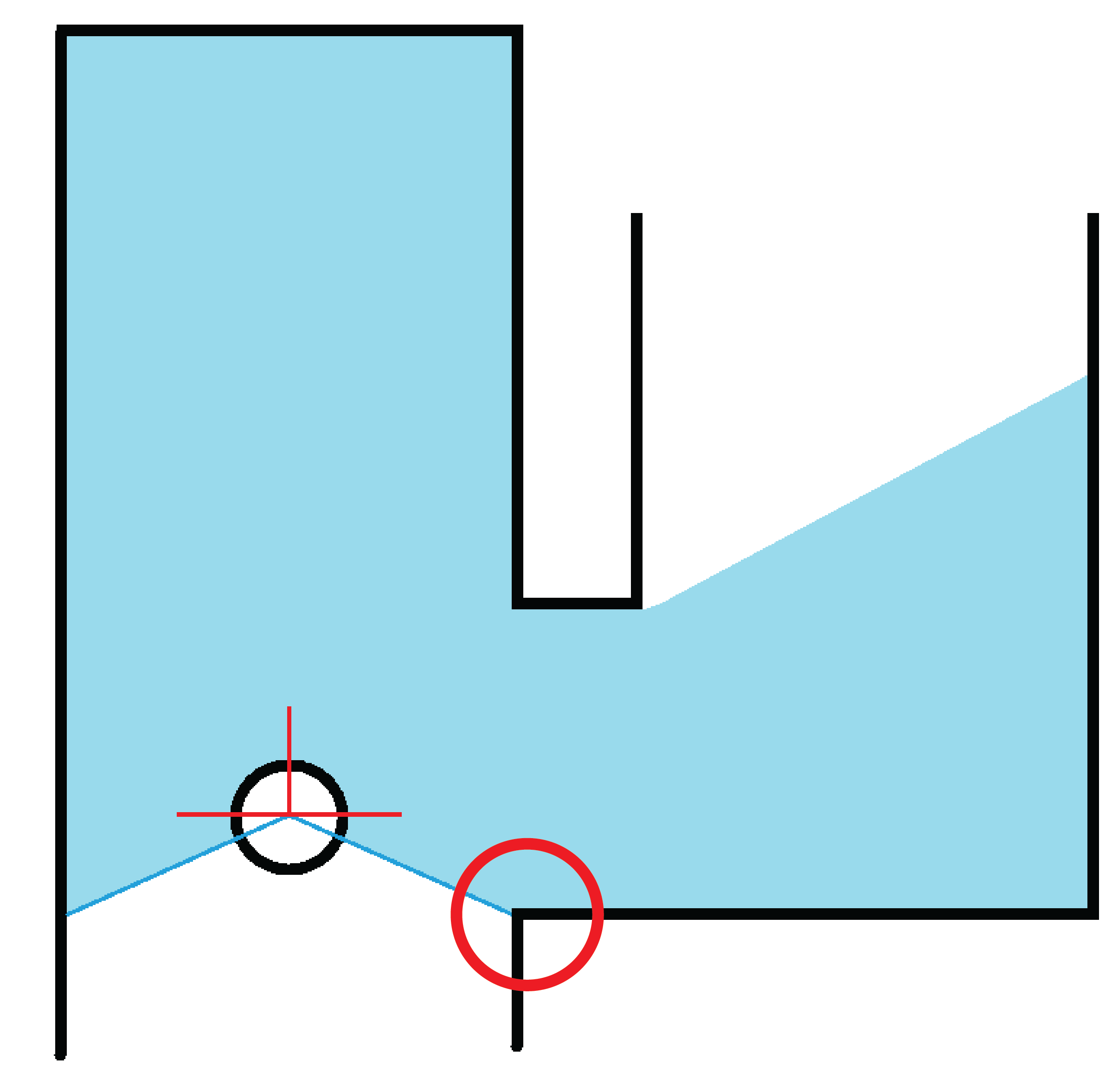
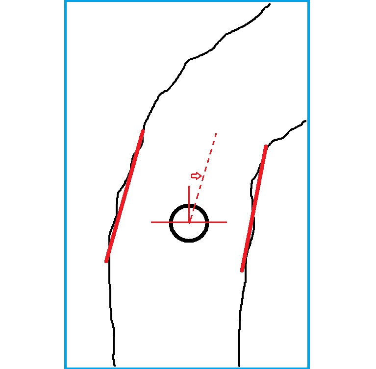
Rotation; At the same time pico will try to find the angle of the corridor (using linedetect) and compensate for that, also with a simple weak P controller. In this case pico has two states, a high precision state where little tolerance is allowed, using lines at the straight or at a 90 degree rotation. If this high precision is not met, than a higher tolerance (-/+ 30 degrees) is allowed to find only the straight. In this case pico can also follow curved/.. walls and other strange situations. But then it is more sensitive to disturbances.
High precision straight driving versus low precision straight driving
Cornering
For cornering the linedetection is used again. As soon as drive receives the order it assumes the corner can be taken. The methods are nearly similar in a right or left rotation.
Cornering is separated in two parts; the first 45 degrees, then the next 45-90 degrees rotation. Only after both parts are done, the cornering is finished and straight driving is continued.
Cornering; first 45 degrees
Cornering; Next 45 to 90 degrees rotation
Pico starts rotating and determines appropriately when the first 45 degrees of the rotation is done. Different (blue) areas are chosen for robustness. If lines at +/- 45 degrees can be found, the first part of the rotation is done and the last part of rotation begins. This last part of the rotation is done as soon as a straight line is found again by linedetect, after which straigth driving is continued. During rotation drive does not listen to the navigation node untill it is done with the corner.
dead end, turn around
In the case of a dead end pico turns in the opposite direction of the tactic, so clockwise. Pico turns for as long as dead end detection is true, and finds a straight afterwards.
Safety
Next to all the other nodes, Pico could still run into problems. In this case pico searches for the most open direction and rotates towards it. For this is searches at a 45 degree angle. Should the safedrive go off, pico will rotate clockwise
Messages and Topics
All the nodes use different Topics and messages to communicate with each other as shown in the framework picture below. Below is an explanation of all the topics and messages.

To make it easy in creating and declerations, for all nodes the same massage type is used. Nevertheless, some values are ignored in some nodes.
pico/dead_end
The Dead end node will publish it results on the pico/dead_end topic. To do this it uses a dead_end message with the following construction:
- bool left
- bool right
- bool straight
pico/corridor
The Corridor node will publish it results on the pico/corridor topic. To do this it uses a corridor message with the following construction:
- bool left
- bool right
- bool straight (Note: straight will be ignored for this node.)
pico/arrow
The Arrow node will publish it results on the pico/arrow topic. To do this it uses a arrow message with the following construction:
- bool left
- bool right
- bool straight (Note: straight will be ignored for this node.)
pico/direction
The Navigation node will publish it results on the pico/Direction topic. To do this it uses a direction message with the following construction:
- int direction
The value of this integer determines the direction as follows:
- 1 = straight
- 2 = left turn
- 3 = right turn
- 4 = 180 deg turn
Maze competition: The result
The maze was completed by our Pico in a time of 1 minute and 7 seconds. This result means we ended 4th out of 12.
The advantage of our script is that every node has to run separately, while this may seem inconvenient, it quickens the start of Pico once the drive node is ran, since all the other nodes are already running. Where Pico stood still the first couple of seconds for other groups, ours already took of like a rocket at the start. Pico succesfully detected both arrows an therefor took the shortest way to the end of the maze. An improvement for the script is with taking corners, on this point we 'lost' the competition, since it was rather slow and not smooth in taking corners.
Time Survey
https://www.dropbox.com/s/40z8zqg9a69aysr/Time%20survey%204K450.xlsx
