Embedded Motion Control 2014 Group 12: Difference between revisions
| Line 146: | Line 146: | ||
A better alternative would be to recognize lines surrounding PICO, instead of data points, and use this information to evaluate the situation. | A better alternative would be to recognize lines surrounding PICO, instead of data points, and use this information to evaluate the situation. | ||
[[File:line_recognition.png |center|thumb|800px|(1) Line recognition of the upcoming junction. The point where the lines intersect is stored for later use (2) The point where the second line of the junction and the corridor meet is saved. | [[File:line_recognition.png |center|thumb|800px|(1) Line recognition of the upcoming junction, which is also robust against small gaps. The point where the two lines intersect is stored for later use. (2) Pico continous to drive until a second line (down the corridor) can be plotted. The point where the second line of the junction and the corridor meet is saved. The two saved points can now be used to estimate the corridor width. (3) Finally, with the width known, an arc is plotted around the corner of the corridor, allowing PICO to go around the corner. Because of the way the new trajectory is plotted, the corner may vary in width while PICO will still be able to end up in the middle of the corridor. ]] | ||
==Changelog== | ==Changelog== | ||
Revision as of 17:23, 25 May 2014
Introduction
Members of group 12
| Groupmembers (email all) | ||
| Name: | Student id: | Email: |
| Anthom van Rijn | 0737682 | e-mail Anthom |
| Jan Donkers | 0724801 | e-mail Jan |
| Jeroen Willems | 0755833 | e-mail Jeroen |
| Karel Drenth | 0863408 | e-mail Karel |
Corridor Challenge
The goal of the corridor challenge is to make pico drive autonomously trhough a corridor, recognize a T-junction successfully, and have it take the appropriate corner.
Planning
Week 1
- First Lecture
Week 2
- C++ tutorials
- ROS tutorials
- SVN tutorials
- Run the first test on pico (safe_drive.cpp) to get some hands-on experience.
Week 3
- Start the actual coding, based on the safe_drive.cpp file. Paying special attention to robustness and exceptions.
- Have pico recognize situations (corridor, corner, t-junction,dead-end, etc.) and act accordingly
- Have the script succesfully run in simulation
Week 4
- Fine tuning of script
- Corridor Competition
Software Architecture
The initial choice was made to first create a robust, well working robot that would successfully recognize a situation using only the laser data, and then take an appropriate action. In this case, it's assumed that all junction/corners are right handed, although it should equally work for left handed situations.
Successfully recognize a situation and take the appropriate action
Be robust against deviations in corruption in the input data
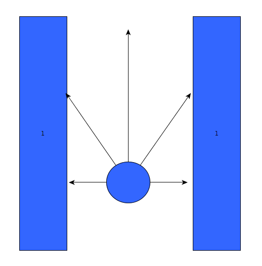
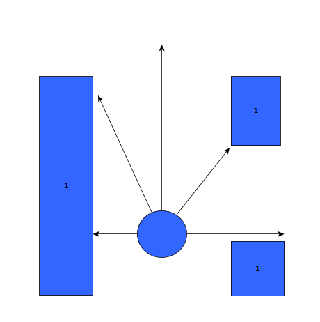
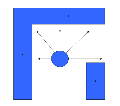
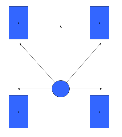
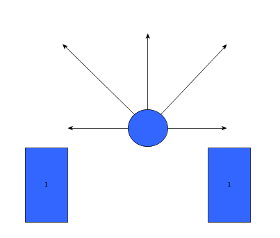
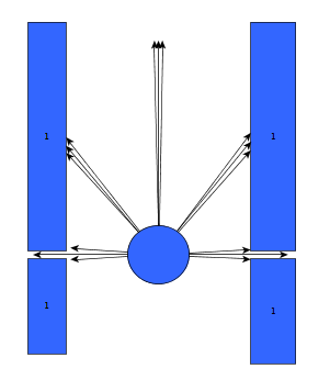
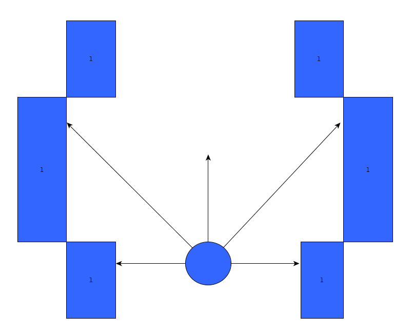
As can be seen, it is important to calibrate the ranges of the laser data to make sure that the situation is evaluated correctly. If this is done wrong, the situation might be evaluated incorrectly and PICO might come to a halt (due to a hard constraint) and be unable to continue. To illustrate this, below are some possible pitfalls and the solution.
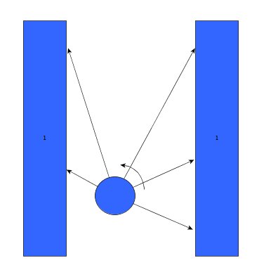
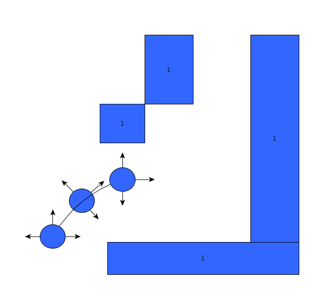
As can be seen in the figures above, it is quite difficult to use only the laser range data to figure out the situations and still be robust for all the things that can be encountered. While the presented situations are good enough for a simple corridor challenge, other alternatives should be considered when regarding finding the way through a maze, for the reliance on proper tuning isn't good practice when writing code.
Experiments
- 09-05-2013
Tested the provided safe_drive file, making small alteration to see the effects on Pico. Tested how hard constrains are handeld and some different safety protocols.
- 13-05-2013
Tried, and failed, to run corridor_challenge_v2 due to numerous bugs in the script (most importantly: stuck in situation zero, unsure what to do). Received help from tutor regarding tips and tricks regarding Qt creator for debugging, building/making C++ in ROS and running simulations. Information was used to create a "how to start: Pico" tutorial. Remainder of time spent on bugfixing.
Change log
09-05
Created scipt corridor_challenge.cpp with basic siteval to recognize conditions
13-05
- Testing corridor_challenge on Pico.
With new input from experiments: updated the corridor_challenge.cpp to corridor_challenge_v2.cpp. Brought the function sit-eval withing the callback loop for sensor messages. This way, the situation is evaluated and updated whenever new laser data is present. Some minor typo's. Added a situation that when things are to close (hard constraint) pico shuts down. After testing it was revealed that pico is stuck in condition 0 (does not know where he is).
15-05
- Revised corridor_challenge_v2.cpp -> renamed to corridorchallenge_v2.cpp and added some new functions:
- Extended laser 'vision' with left- and right diagonal view and updated amount of laser data used for each 'vision' vector.
- Extended the amount of possible situation PICO can be in to nine. Currently using:
- Corridor
- T-Junction (L+R)
- Crossing
- Corner (L+R)
- Dead End
- Exit
- Added a function that compares the left and right laser data and 'strafes' PICO to the middle using the y coordinate.
- Added an 'integrator'-like function that aligns the front vector of PICO to the walls of the corridor.
- Included front laser data to this function to ensure 'backup' when PICO comes too close to a wall.
- Added corresponding functions to new situations.
- Tweaked variables to ensure functioning simulations. (Allowance of some initial angle with reference to wall 'disturbance'). PICO is currently able to pass corridors, T-junctions and corners, for this however, the amount of possible situations PICO can be in is reduced for the sake of simplicity.
Final Design
The final design that was used was corridor_challenge_v2. It's goal was to use the laser data to recognize one of 9 conditions (ranging from freedom, corridor) and act in a preprogrammed way (outside of the loop) on how to handle these, and then turn on the loop again.
Result
Due to some unforeseen circumstances, corridorchallenge v3 failed to load on PICO. We resorted back to v2, which, while less robust, was still able to find the t-junction and act accordingly. The result was a first place in the "limited speed" category, with a time close to 20 seconds.
Maze Challenge
The goal of the Maze Challenge is to have PICO drive autonomously through a maze and successfully navigate itself towards the exit. There are three major assumptions
- (1) The Maze is two dimensional (all the walls, as well as the entrance and exits are on the ground floor level. There is no way to go either up or down).
- (2) Both the entrance and the exits are on the outer edge of the maze.
- (3) The maze does not change with time.
While these assumptions might seem redundant, they are of major importance when determining the strategy
Planning
Week 5
- Group meeting discussing the new strategy to finish solve the maze challenge
- Start coding on the line detection script
Week 6
- Lecture
Week 7
- Lecture
Week 8
- Lecture
Software architecture / Road map
When regarding the designed software from the corridor competition, it became apparent that simply reading out the laser range data and comparing it against a set of reference values to determine the current situation was not really a robust solution. A better alternative would be to recognize lines surrounding PICO, instead of data points, and use this information to evaluate the situation.

Changelog
Experiments
Final Design
Final result
PICO succesfully found the exit
