System Architecture MSD19: Difference between revisions
No edit summary |
|||
| (34 intermediate revisions by 3 users not shown) | |||
| Line 6: | Line 6: | ||
__TOC__ | __TOC__ | ||
Autonomous drone referee system architecture has been | |||
=Architectural Framework= | |||
<span style="color:black"> | |||
Autonomous drone referee system architecture has been implemented by taking into account both CAFCR[1] and SafeRobots[2] frameworks. The focus in the project has been heavily concentrated towards the design and implementation having derived the requirement specifications and hardware resources available. Our goal can be described in three folds; (1) Use Crazyflie as the development platform, (2) Design an autonomous path planning strategy, (3) Make use of a perception system and integrate into simulation environment. As a tailored approach to our goals, the team developed the system-level reasoning based on abstract knowledge defined in the problem space. The defined goals together with the requirements mentioned below formalised our context of the problem. Then design choices were made based on thereof to define the solution space consisting of hardware and other tools to utilize, algorithms for path planning and communication protocols. This namely was the design time and opportunity to mitigate uncertainties. The operational space covers the process of developing tangible deliverables that satisfy functional and non-functional requirements that were initially prescribed. | |||
The overall methodology of our road-map can be found in the table below: | |||
'''Problem Space''' | |||
* Requirement 1: Develop a safe system that will not cause damage or harm in case of malfunction | |||
* Requirement 2: Choose a solution that will enable to develop the project from simple to complex | |||
* Requirement 3: Formalize solution such that it can be transferable to future work | |||
* Context 1: Drone platform and display | |||
* Context 2: Robot soccer MSL | |||
* Problem 1: How to track a ball for a referee such that they can make clear decisions | |||
* Problem 2: How to design a system using low computational resources | |||
'''Solution Space''' | |||
* Perception: Computer vision, Deep NN | |||
* Navigation: Path planning in 1D, Path planning in 2D | |||
* Platform: Crazyflie, Sensors, Camera, Power | |||
* Communication: UWB, Radio | |||
'''Operation Space''' | |||
* Middleware: ROS, Crazyflie | |||
* External Code Libraries: Craztflie_lib, OpenCV, libraries in Python | |||
* Implementation: Executable software code, Virtual simulation | |||
* Deployment: Model tests, hardware tests, software debugging | |||
</span> | |||
=System Decomposition= | |||
In this section, we develop our hypothetical framework that covers the entire strategy for the drone referee system and later conclude with the realised version. The essence in both models is that they give a perspective of how each component interacts with one another when the system is operational. | |||
The system is operational when the drone platform is in flight under a controlled manner to detect and track the ball in the play area of the Tech United soccer field. Furthermore, when the gameplay is visualised in the simulated environment showing what the drone captures. | |||
The system decomposition is outlined in the following sub-sections. | |||
==Ideal Strategy== | |||
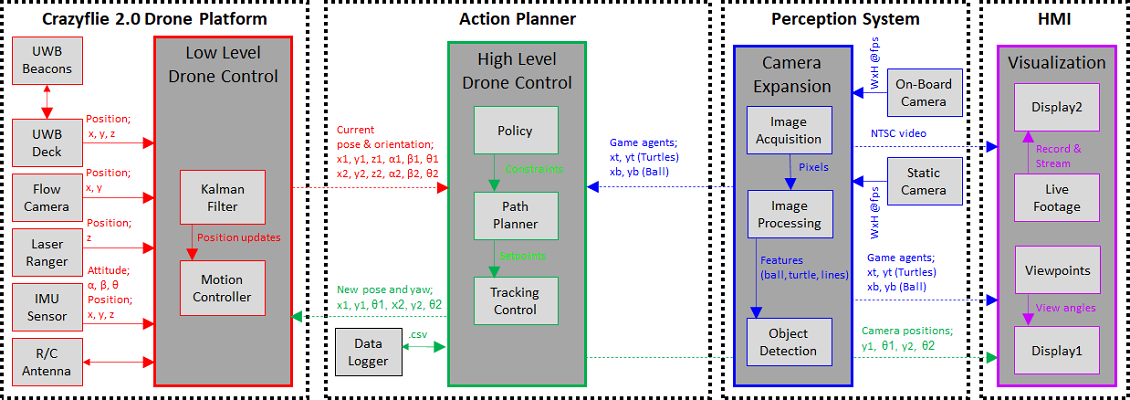
The strategy of the project prompted us to fuse 4 component groups; | |||
* Crazyflie 2.0 Drone Platform: A drone platform which carries out the mobile tasks, capable to control autonomously. | |||
** Kalman Filter: Estimates the position of drone based on sensor measurements (IMU, Flowdeck, UWB system) | |||
** Motion Controller: Generates control outputs into the motor drivers. | |||
** Sensor inputs: Drone pose coordinates (longitudinal axis; x, horizontal axis; y, vertical axis; z) and attitude (roll; α, pitch; β, yaw; θ) | |||
* Action Planner: Generates kinematic parameters provided to drone and into the Visualizer concurrently. | |||
** Policy: Preset constraints such as ball is always assumed on ground level, drone does not change altitude, constant roll | |||
** Path Planner: 2 different path planning algorithms which were individually developed. | |||
** Tracking Control: Tracking the the gameplay (i.e. ball) via the path planning logic. | |||
* Perception: Streams and processes images for an HMI and incorporates perception functions. | |||
** Image Processing: Methods such as transformation, HSV Color mapping. | |||
** Object Detection: Based on Matlab toolboxes and OpenCV frameworks. | |||
* HMI: Virtually plays the game and visualises according to given motion commands. Provides game footage. | |||
** Display1: FoV in simulator. | |||
** Display2: Streams live footage to viewer. | |||
<center>[[File:Strategy v3.png]]</center> | |||
==Realised Strategy== | |||
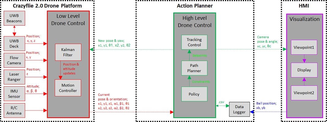
The realised system however at its state can also perform autonomous flight and simulation without using perception. Although perception has been developed and tested successfully it has not been fully integrated with the design pipeline. Therefore we present the following components in the current prototype; | |||
* Crazyflie 2.0 Drone Platform: A drone platform which carries out the mobile tasks, capable to control autonomously. | |||
* Action Planner: Generates kinematic parameters provided to drone and into the Visualizer concurrently. | |||
* HMI: Virtually plays the game and visualises according to given motion commands. | |||
<center>[[File:Realised v3.png]]</center> | |||
=Layered System Hierarchy= | |||
Based on the aforementioned architectures, the system was tested at various stages ensuring at each layer of abstraction the design is sufficiently developed. The hierarchy between each layer indicates the functionalities needed to achieve the requirements of the design[3]. Enabling the lower layers to use information obtained from the upper layer. Decisions taken for team division, coordination and work packages were accordingly mapped with milestones and deadlines to handle the items at each layer as the project progressed. | |||
A selection was made in the workflow on the priority for which every functionality contributes towards as seen below. Several functions more of which regarding perception together with the hardware integration of this function and integration with navigation is part of our future work. | |||
<center>[[File:Roadmap v2.png]]</center> | |||
=References= | |||
[1] Muller, Gerrit. 2018. System Architecting, vol. 18, Gaudí Systems Architecting, http://www.gaudisite.nl | |||
[2] Ramaswamy, Arunkumar et al. “SafeRobots: A model-driven Framework for developing Robotic Systems”. 2014 IEEE/RSJ: 1517-1524. | |||
[3] Maier, Mark W. 2009. The Art of Systems Architecting, 3rd Edition. Hoboken: CRC Press. p164 | |||
Latest revision as of 15:42, 17 April 2020
Architectural Framework
Autonomous drone referee system architecture has been implemented by taking into account both CAFCR[1] and SafeRobots[2] frameworks. The focus in the project has been heavily concentrated towards the design and implementation having derived the requirement specifications and hardware resources available. Our goal can be described in three folds; (1) Use Crazyflie as the development platform, (2) Design an autonomous path planning strategy, (3) Make use of a perception system and integrate into simulation environment. As a tailored approach to our goals, the team developed the system-level reasoning based on abstract knowledge defined in the problem space. The defined goals together with the requirements mentioned below formalised our context of the problem. Then design choices were made based on thereof to define the solution space consisting of hardware and other tools to utilize, algorithms for path planning and communication protocols. This namely was the design time and opportunity to mitigate uncertainties. The operational space covers the process of developing tangible deliverables that satisfy functional and non-functional requirements that were initially prescribed.
The overall methodology of our road-map can be found in the table below:
Problem Space
- Requirement 1: Develop a safe system that will not cause damage or harm in case of malfunction
- Requirement 2: Choose a solution that will enable to develop the project from simple to complex
- Requirement 3: Formalize solution such that it can be transferable to future work
- Context 1: Drone platform and display
- Context 2: Robot soccer MSL
- Problem 1: How to track a ball for a referee such that they can make clear decisions
- Problem 2: How to design a system using low computational resources
Solution Space
- Perception: Computer vision, Deep NN
- Navigation: Path planning in 1D, Path planning in 2D
- Platform: Crazyflie, Sensors, Camera, Power
- Communication: UWB, Radio
Operation Space
- Middleware: ROS, Crazyflie
- External Code Libraries: Craztflie_lib, OpenCV, libraries in Python
- Implementation: Executable software code, Virtual simulation
- Deployment: Model tests, hardware tests, software debugging
System Decomposition
In this section, we develop our hypothetical framework that covers the entire strategy for the drone referee system and later conclude with the realised version. The essence in both models is that they give a perspective of how each component interacts with one another when the system is operational. The system is operational when the drone platform is in flight under a controlled manner to detect and track the ball in the play area of the Tech United soccer field. Furthermore, when the gameplay is visualised in the simulated environment showing what the drone captures. The system decomposition is outlined in the following sub-sections.
Ideal Strategy
The strategy of the project prompted us to fuse 4 component groups;
- Crazyflie 2.0 Drone Platform: A drone platform which carries out the mobile tasks, capable to control autonomously.
- Kalman Filter: Estimates the position of drone based on sensor measurements (IMU, Flowdeck, UWB system)
- Motion Controller: Generates control outputs into the motor drivers.
- Sensor inputs: Drone pose coordinates (longitudinal axis; x, horizontal axis; y, vertical axis; z) and attitude (roll; α, pitch; β, yaw; θ)
- Action Planner: Generates kinematic parameters provided to drone and into the Visualizer concurrently.
- Policy: Preset constraints such as ball is always assumed on ground level, drone does not change altitude, constant roll
- Path Planner: 2 different path planning algorithms which were individually developed.
- Tracking Control: Tracking the the gameplay (i.e. ball) via the path planning logic.
- Perception: Streams and processes images for an HMI and incorporates perception functions.
- Image Processing: Methods such as transformation, HSV Color mapping.
- Object Detection: Based on Matlab toolboxes and OpenCV frameworks.
- HMI: Virtually plays the game and visualises according to given motion commands. Provides game footage.
- Display1: FoV in simulator.
- Display2: Streams live footage to viewer.

Realised Strategy
The realised system however at its state can also perform autonomous flight and simulation without using perception. Although perception has been developed and tested successfully it has not been fully integrated with the design pipeline. Therefore we present the following components in the current prototype;
- Crazyflie 2.0 Drone Platform: A drone platform which carries out the mobile tasks, capable to control autonomously.
- Action Planner: Generates kinematic parameters provided to drone and into the Visualizer concurrently.
- HMI: Virtually plays the game and visualises according to given motion commands.

Layered System Hierarchy
Based on the aforementioned architectures, the system was tested at various stages ensuring at each layer of abstraction the design is sufficiently developed. The hierarchy between each layer indicates the functionalities needed to achieve the requirements of the design[3]. Enabling the lower layers to use information obtained from the upper layer. Decisions taken for team division, coordination and work packages were accordingly mapped with milestones and deadlines to handle the items at each layer as the project progressed. A selection was made in the workflow on the priority for which every functionality contributes towards as seen below. Several functions more of which regarding perception together with the hardware integration of this function and integration with navigation is part of our future work.

References
[1] Muller, Gerrit. 2018. System Architecting, vol. 18, Gaudí Systems Architecting, http://www.gaudisite.nl
[2] Ramaswamy, Arunkumar et al. “SafeRobots: A model-driven Framework for developing Robotic Systems”. 2014 IEEE/RSJ: 1517-1524.
[3] Maier, Mark W. 2009. The Art of Systems Architecting, 3rd Edition. Hoboken: CRC Press. p164