Embedded Motion Control 2019 Group 8: Difference between revisions
No edit summary |
|||
| Line 1: | Line 1: | ||
=Group Members= | |||
{| border="1" cellpadding="5" cellspacing="1" style="display: inline-table;" | {| border="1" cellpadding="5" cellspacing="1" style="display: inline-table;" | ||
! Name | ! Name | ||
Revision as of 10:09, 27 May 2019
Group Members
| Name | Student ID | |
|---|---|---|
| Stan (C.M.) den Hartog | 0953184 | c.m.d.hartog@student.tue.nl |
| Elise (E.D.T.) Verhees | 0950109 | e.d.t.verhees@student.tue.nl |
| Rob (R.J.G.) Dorussen | 0968849 | r.j.g.dorussen@student.tue.nl |
| Gosse (G.) Bijlenga | 0950642 | g.bijlenga@student.tue.nl |
| Max (M.J.) van Haren | 0953564 | m.j.v.haren@student.tue.nl |
Introduction
In the course Embedded Motion Control (EMC) the software design of an autonomous robot is given as an objective. The implementation of the software skills to fulfill
Design
Design Document
Requirements
- Autonomously complete the 'Escape Room'.
- Must not bump into the wall.
- Must not tip over.
- Make sensible movements/progress each 30 seconds.
- Software must be easy to set up.
- Robot must function robustly.
Specifications
- Rear wheel must cross the finish line.
- The robot should finish within 5 minutes.
- The robot should finish within 2 trials.
- Distance between the wall and the robot must be 0,05 meter.
- The maximum translational speed is 0,5 meter per second.
- The maximum rotational speed is 1.2 radians per second.
- The robot must have a maximum speed/stop before changing direction.
- The maximum inclination angle is around 5 degrees.
- The software must have 1 command to update.
- The software should be able to compile (cmake/make).
- The software should start by calling upon one executable.
- The status must be reported at least each 30 seconds.
- The functions must be scalable.
- Definition of data ownership must be explicit.
- Switch states only to advance the strategy plan.
Functions
- Detect if the robot is over the finish line
- Drive forward (keeping the speed specifications in mind)
- Rotate
- Collision detection
- (Update World Model)
- Print status
- Scan environment for exit
- State function/ Life Cycle State Machine (LCSM)
- Wall hugging
Components
- Room
- Walls
- Finish line
- Exit tunnel
- (Obstacles)
- Robot
- Actuators
- Sensors
- Body
- Hardware
- Software
- World Model
- Interfaces
- Plan
- Actuator control
- Monitoring
- Preception
- Mediation
- Life Cycle State Machine (LCSM)
Escape Room Execution
Wall Following
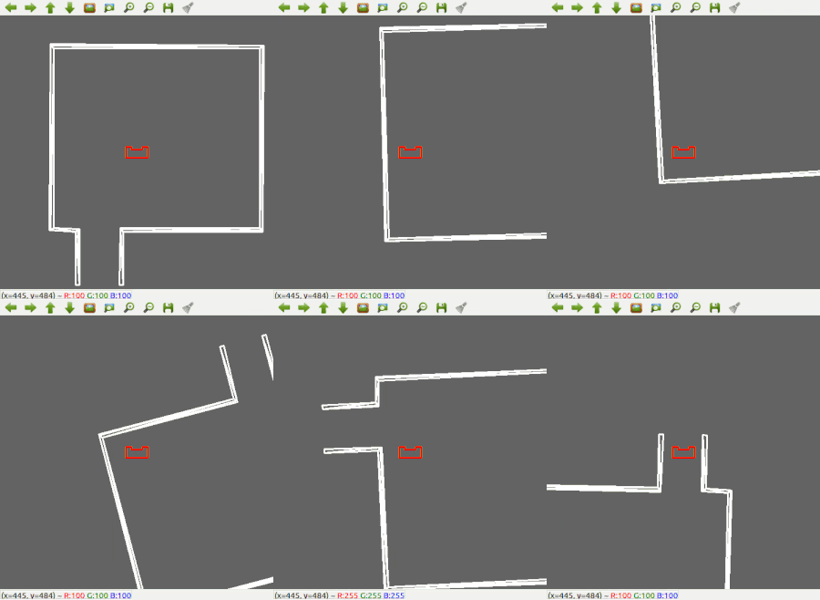
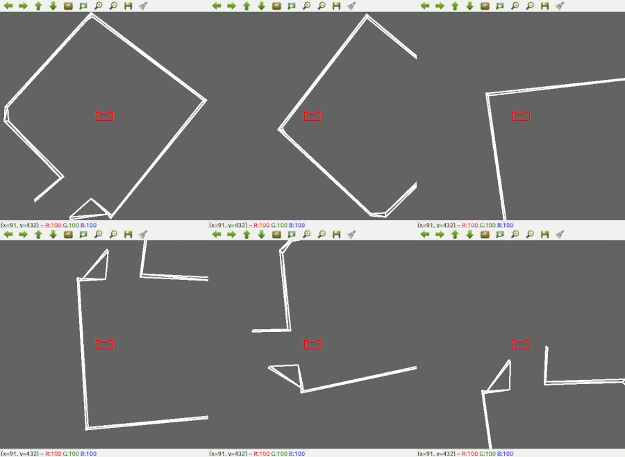
For the escape room challenge, all the functions and components described above are programmed using C++. Since the most robust solution is to follow a wall, this is chosen to be implemented first. The decision has been made to make the robot always keep the wall on its left side. For the Hospital challenge this will have to be expanded to also being able to follow a wall on the right side. Good results are achieved in the 2 random maps that are shown below.
Scanning for an exit
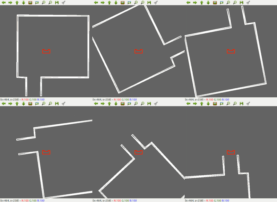
Next, the robot is made a bit 'smarter'; It will first scan the room for an exit. If an exit is found, it will stop rotating, rotate a bit back, to make sure it will head for the left wall, start heading for the exit, and then continue with the wall following procedure to further exit the corridor. The results for this can be seen below.
Escape Room Resullt
Hospital Challenge Brainstorm Session
To prepare for the hospital session, a brainstorm session is done and several new requirements, specifications, functions and components are thought of.
The following diagram is the result of this brainstorm session.


