Embedded Motion Control/Hardware: Difference between revisions
Created page with 'In this chapter the different LEGO parts are discussed in more detail. ==RCX== The RCX contains a CPU, display, memory, three actuator output ports and three sensor input ports.…' |
No edit summary |
||
| (One intermediate revision by the same user not shown) | |||
| Line 2: | Line 2: | ||
==RCX== | ==RCX== | ||
The RCX contains a CPU, display, memory, three actuator output ports and three sensor input ports. The output ports (A, B and C) can be operated in three modes: on, off or floating. When an output is turned on, it can run either in a forward or reverse direction. The output power level can be adjusted using pulse width modulation (PWM). The sensor ports (1, 2 and 3) can be used for both passive and active (powered) sensors. What kind of sensor is used has to be told to the RCX by a program. For each sensor, the sensor type and sensor mode have to be configured. The sensor type defines the interaction. The sensor mode determines the interpretation of the sensor values. The LCD can display four-digit signed numbers, single-digit unsigned numbers and special indicators. The RCX can communicate with a computer or another RCX through infrared. The RCX is powered by six AA batteries. | [[File:Emc-005.jpg|right|thumb|190px|Figure 3.1: The RCX]] | ||
The RCX contains a CPU, display, memory, three actuator output ports and three sensor input ports. The output ports (A, B and C) can be operated in three modes: on, off or floating. When an output is turned on, it can run either in a forward or reverse direction. The output power level can be adjusted using pulse width modulation (PWM). The sensor ports (1, 2 and 3) can be used for both passive and active (powered) sensors. What kind of sensor is used has to be told to the RCX by a program. For each sensor, the sensor type and sensor mode have to be configured. The sensor type defines the interaction. The sensor mode determines the interpretation of the sensor values. The LCD can display four-digit signed numbers, single-digit unsigned numbers and special indicators. The RCX can communicate with a computer or another RCX through infrared. The RCX is powered by six AA batteries. | |||
==Temperature sensor== | ==Temperature sensor== | ||
[[File:Emc-006.jpg|right|thumb|190px|Figure 3.2: Temperature sensor]] | |||
The LEGO temperature sensor measures using a thermistor (temperature sensitive resistor), i.e. the resistance of the thermistor changes with temperature. The resistance is measured by a circuit and converted to a temperature. It is a passive analog sensor. The temperature sensor is calibrated from -20° Celsius to +50° Celsius. The RCX can read and display the temperature in either Fahrenheit or Celsius. | The LEGO temperature sensor measures using a thermistor (temperature sensitive resistor), i.e. the resistance of the thermistor changes with temperature. The resistance is measured by a circuit and converted to a temperature. It is a passive analog sensor. The temperature sensor is calibrated from -20° Celsius to +50° Celsius. The RCX can read and display the temperature in either Fahrenheit or Celsius. | ||
==Light sensor== | ==Light sensor== | ||
[[File:Emc-007.jpg|right|thumb|190px|Figure 3.3 Light sensor]] | |||
The light sensor is an active sensor used to detect the amount of lightness and darkness. When the sensor is pointed at a surface, it reads the amount of reflected light. A light surface or a bright light results in a higher value than a black surface or shadowed object. It can also respond to blinking objects. The light sensor both emits and detects light. Therefore it can measure the amount of light in a room or the reflected amount of light from a surface. The light sensor can be used for line detection, edge detection or light/dark seeking purposes. In this course the light sensor will be used for edge detection. | The light sensor is an active sensor used to detect the amount of lightness and darkness. When the sensor is pointed at a surface, it reads the amount of reflected light. A light surface or a bright light results in a higher value than a black surface or shadowed object. It can also respond to blinking objects. The light sensor both emits and detects light. Therefore it can measure the amount of light in a room or the reflected amount of light from a surface. The light sensor can be used for line detection, edge detection or light/dark seeking purposes. In this course the light sensor will be used for edge detection. | ||
==Rotation sensor== | ==Rotation sensor== | ||
[[File:Emc-008.jpg|right|thumb|190px|Figure 3.4 Rotation sensor]] | |||
The rotation sensor measures rotation with a resolution of 16 increments per revolution. The sensor uses two light diodes and an encoder disc with 4 slots which results in a quadrature signal with the mentioned resolution of 16 inc/rev. The resolution can be altered by applying a transmission between the motor and the rotation sensor. The maximum working speed of the rotation sensor equals 500 RPM. Note that at very low or very high speeds it is possible that counts are missed. | The rotation sensor measures rotation with a resolution of 16 increments per revolution. The sensor uses two light diodes and an encoder disc with 4 slots which results in a quadrature signal with the mentioned resolution of 16 inc/rev. The resolution can be altered by applying a transmission between the motor and the rotation sensor. The maximum working speed of the rotation sensor equals 500 RPM. Note that at very low or very high speeds it is possible that counts are missed. | ||
==Motor== | ==Motor== | ||
The motor has an internal five-stages gear reduction to increase the torque and a weight of 28 g. If no load is attached to the motor, the rotational speed equals 340 RPM and the no-load current equals 3.5 mA | [[File:Emc-009.jpg|right|thumb|190px|Figure 3.5 Motor]] | ||
The motor has an internal five-stages gear reduction to increase the torque and a weight of 28 g. If no load is attached to the motor, the rotational speed equals 340 RPM and the no-load current equals 3.5 mA <ref name="Hurbain">Philippe Hurbain. ''Philo’s Home Page: LEGO Mindstorms''. http://philohome.com/.</ref>. The rotation speed of the motor is proportional to the voltage applied to it. The stall torque (locked motor axle shaft) of the motor equals 5.5 Ncm, the stall current equals 340 mA. Despite of the presence of an internal thermistor, avoid long stall periods in order to prevent overheating of the motor <ref name="Hurbain">Philippe Hurbain. ''Philo’s Home Page: LEGO Mindstorms''. http://philohome.com/.</ref>. | |||
==USB IR tower== | ==USB IR tower== | ||
[[File:Emc-010.jpg|right|thumb|190px|Figure 3.6 USB IR tower]] | |||
The RCX communicates to a computer through IR light. To receive the signals from the RCX, the USB IR tower can be used. For computers which already have an IR port, still the tower has to be used. Most standard IR ports use IrDA for communication, while the RCX uses a simpler proprietary protocol. The IR tower programs can be used to download control programs to the RCX and to upload data to the computer. The IR tower and the RCX must face each other to establish communication. | The RCX communicates to a computer through IR light. To receive the signals from the RCX, the USB IR tower can be used. For computers which already have an IR port, still the tower has to be used. Most standard IR ports use IrDA for communication, while the RCX uses a simpler proprietary protocol. The IR tower programs can be used to download control programs to the RCX and to upload data to the computer. The IR tower and the RCX must face each other to establish communication. | ||
== Connecting wire== | == Connecting wire== | ||
[[File:Emc-011.jpg|right|thumb|190px|Figure 3.7 Connecting wire]] | |||
The connecting wire can be used to connect the motor to the RCX or to extend the connection wires of the various LEGO parts. No specific orientation of the connectors is required. | The connecting wire can be used to connect the motor to the RCX or to extend the connection wires of the various LEGO parts. No specific orientation of the connectors is required. | ||
Latest revision as of 14:05, 25 March 2011
In this chapter the different LEGO parts are discussed in more detail.
RCX
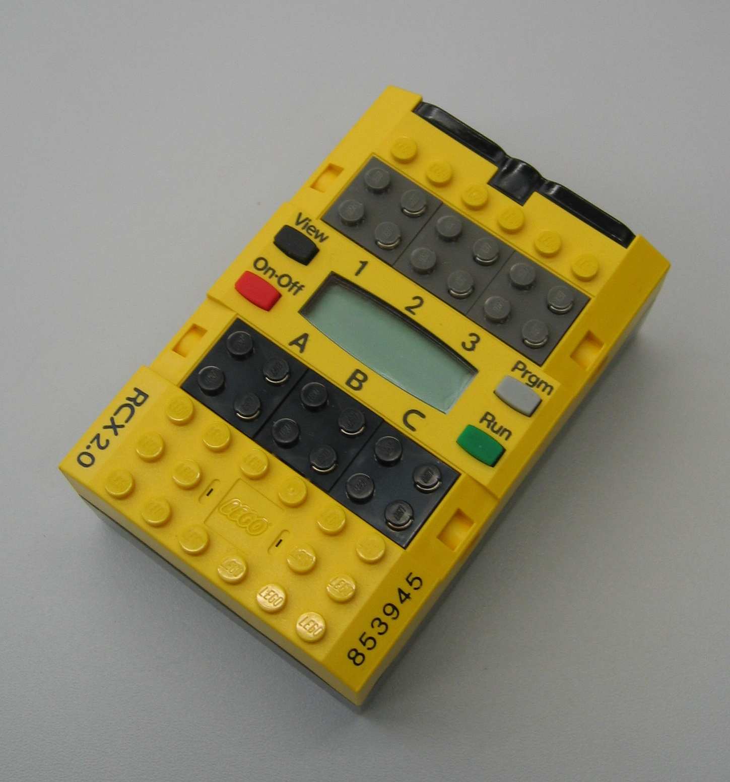
The RCX contains a CPU, display, memory, three actuator output ports and three sensor input ports. The output ports (A, B and C) can be operated in three modes: on, off or floating. When an output is turned on, it can run either in a forward or reverse direction. The output power level can be adjusted using pulse width modulation (PWM). The sensor ports (1, 2 and 3) can be used for both passive and active (powered) sensors. What kind of sensor is used has to be told to the RCX by a program. For each sensor, the sensor type and sensor mode have to be configured. The sensor type defines the interaction. The sensor mode determines the interpretation of the sensor values. The LCD can display four-digit signed numbers, single-digit unsigned numbers and special indicators. The RCX can communicate with a computer or another RCX through infrared. The RCX is powered by six AA batteries.
Temperature sensor
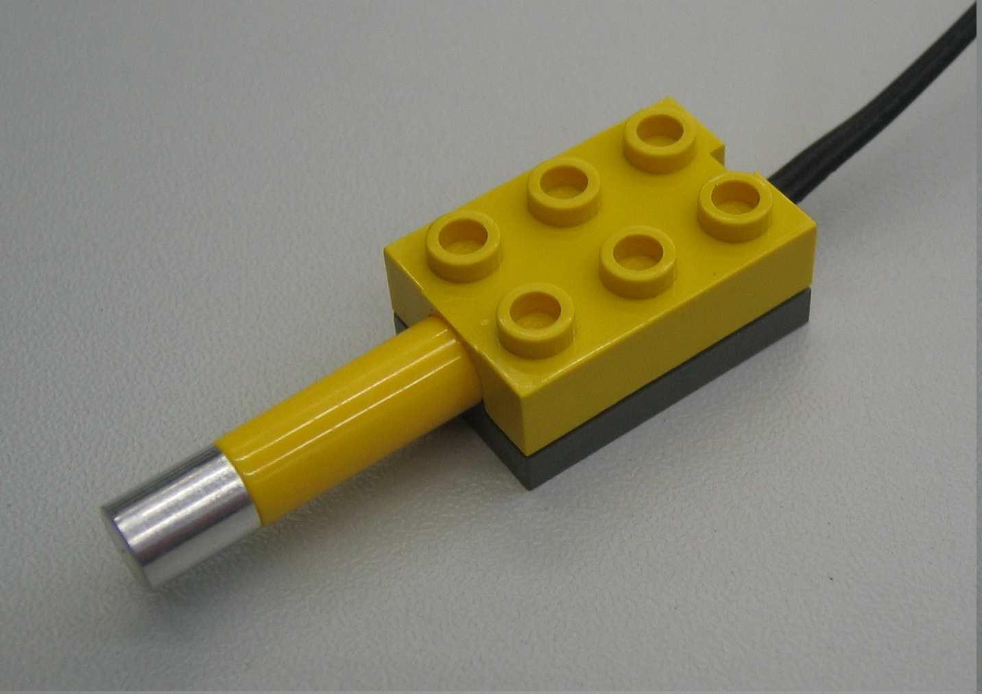
The LEGO temperature sensor measures using a thermistor (temperature sensitive resistor), i.e. the resistance of the thermistor changes with temperature. The resistance is measured by a circuit and converted to a temperature. It is a passive analog sensor. The temperature sensor is calibrated from -20° Celsius to +50° Celsius. The RCX can read and display the temperature in either Fahrenheit or Celsius.
Light sensor
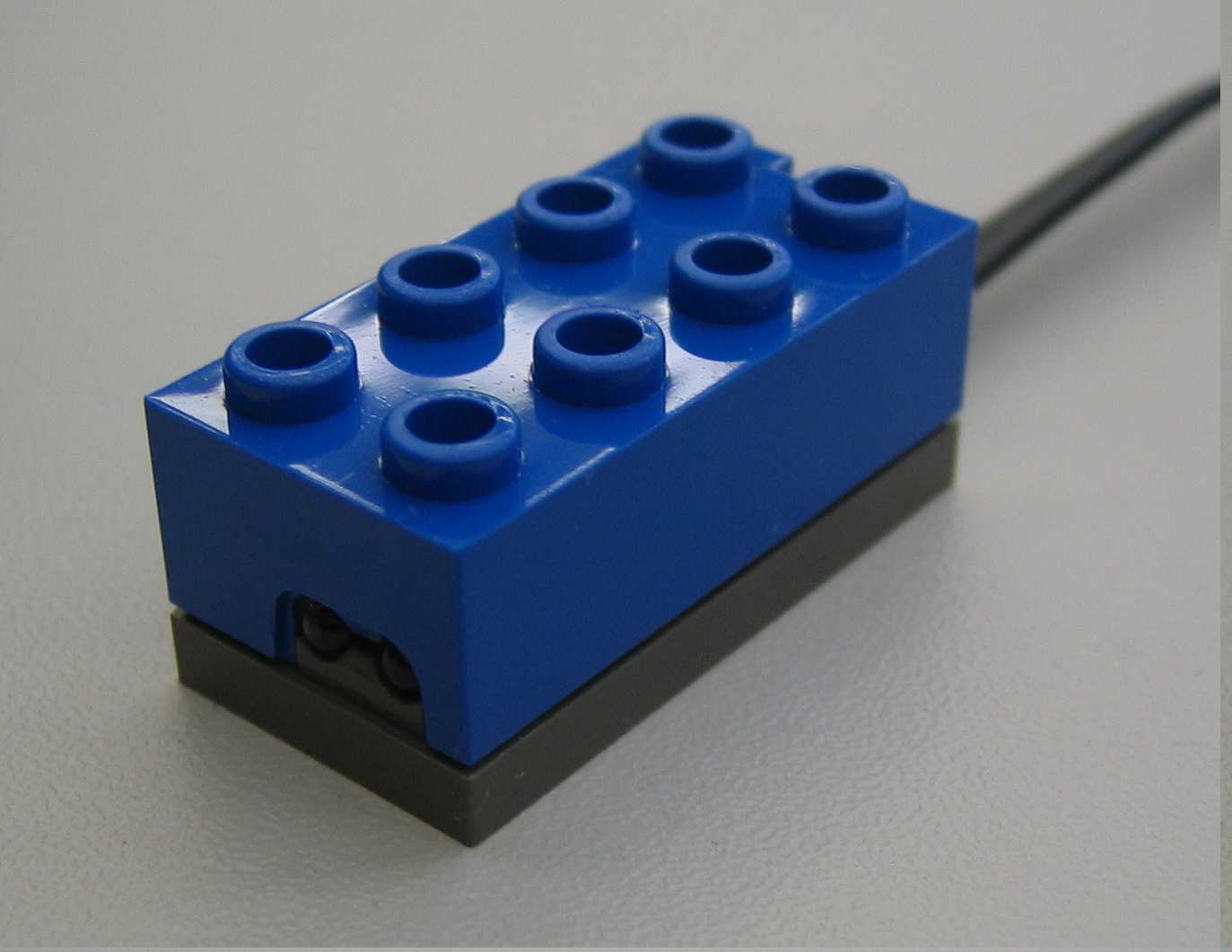
The light sensor is an active sensor used to detect the amount of lightness and darkness. When the sensor is pointed at a surface, it reads the amount of reflected light. A light surface or a bright light results in a higher value than a black surface or shadowed object. It can also respond to blinking objects. The light sensor both emits and detects light. Therefore it can measure the amount of light in a room or the reflected amount of light from a surface. The light sensor can be used for line detection, edge detection or light/dark seeking purposes. In this course the light sensor will be used for edge detection.
Rotation sensor
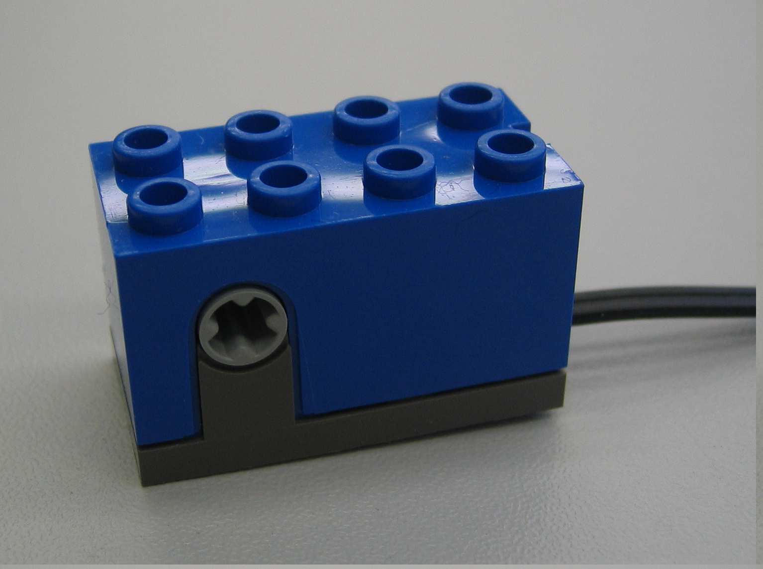
The rotation sensor measures rotation with a resolution of 16 increments per revolution. The sensor uses two light diodes and an encoder disc with 4 slots which results in a quadrature signal with the mentioned resolution of 16 inc/rev. The resolution can be altered by applying a transmission between the motor and the rotation sensor. The maximum working speed of the rotation sensor equals 500 RPM. Note that at very low or very high speeds it is possible that counts are missed.
Motor
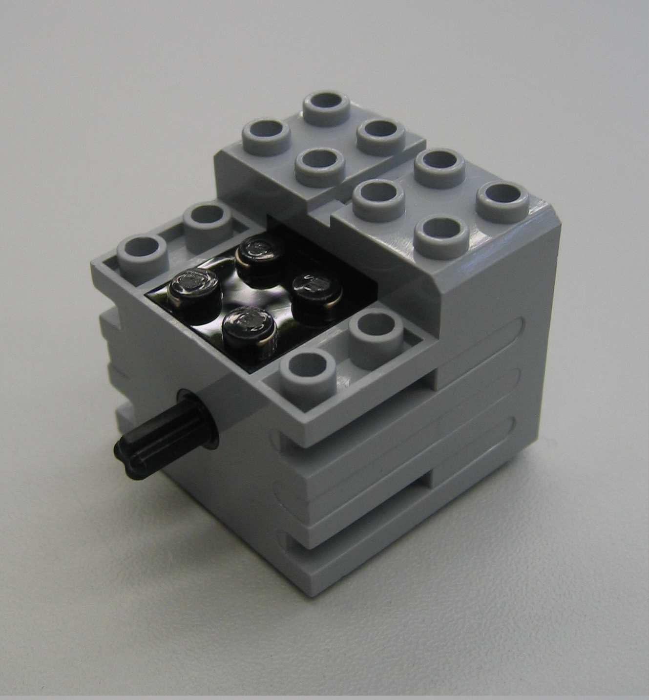
The motor has an internal five-stages gear reduction to increase the torque and a weight of 28 g. If no load is attached to the motor, the rotational speed equals 340 RPM and the no-load current equals 3.5 mA [1]. The rotation speed of the motor is proportional to the voltage applied to it. The stall torque (locked motor axle shaft) of the motor equals 5.5 Ncm, the stall current equals 340 mA. Despite of the presence of an internal thermistor, avoid long stall periods in order to prevent overheating of the motor [1].
USB IR tower
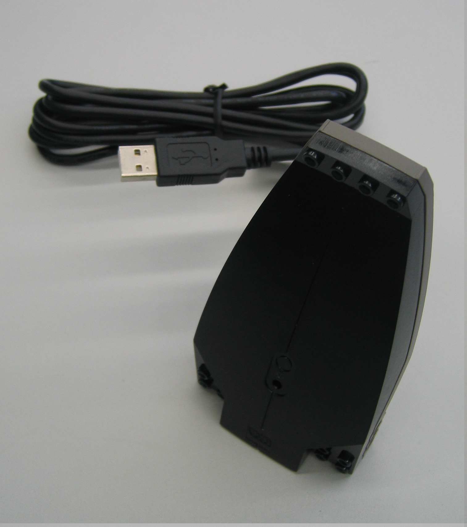
The RCX communicates to a computer through IR light. To receive the signals from the RCX, the USB IR tower can be used. For computers which already have an IR port, still the tower has to be used. Most standard IR ports use IrDA for communication, while the RCX uses a simpler proprietary protocol. The IR tower programs can be used to download control programs to the RCX and to upload data to the computer. The IR tower and the RCX must face each other to establish communication.
Connecting wire
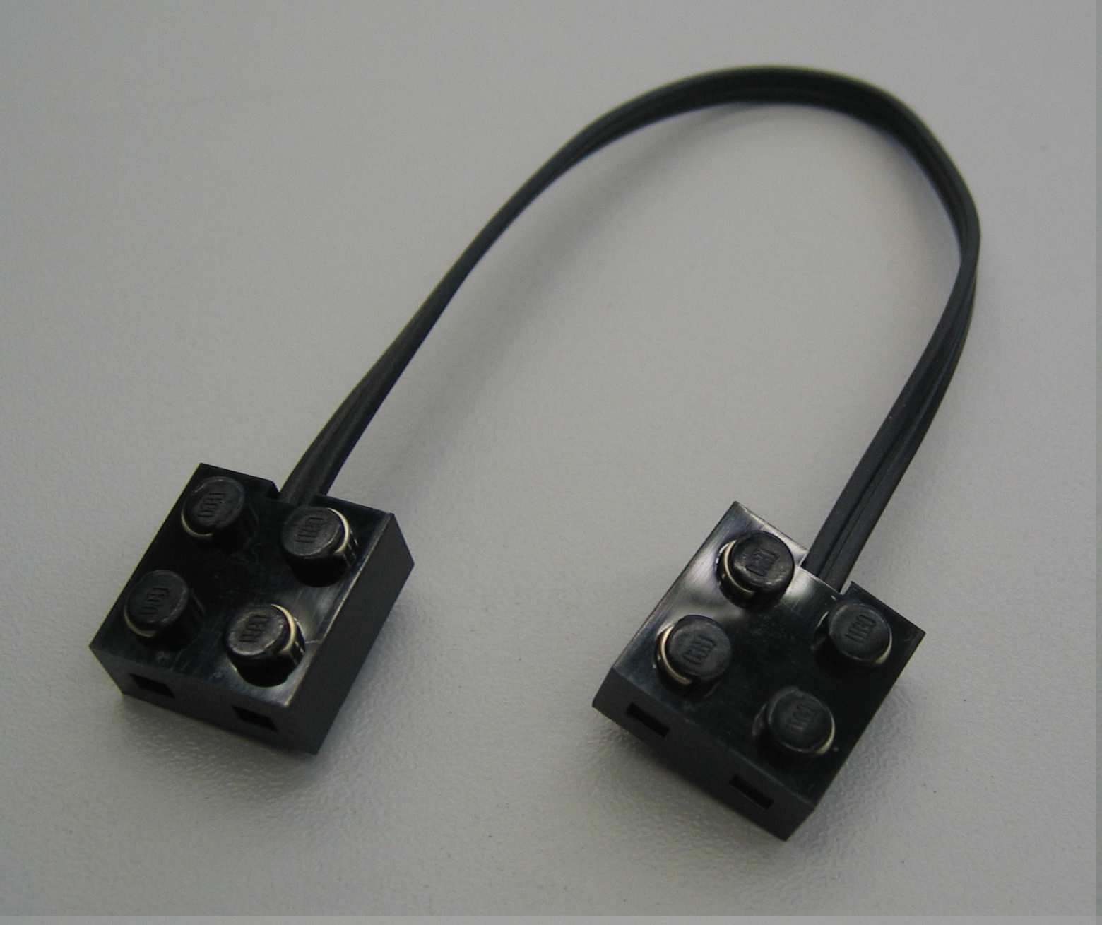
The connecting wire can be used to connect the motor to the RCX or to extend the connection wires of the various LEGO parts. No specific orientation of the connectors is required.
- ↑ 1.0 1.1 Philippe Hurbain. Philo’s Home Page: LEGO Mindstorms. http://philohome.com/.