Drone Referee - MSD 2018/9: Difference between revisions
| Line 145: | Line 145: | ||
The other sub-systems will take action based on the high level abstract states. In figure , a context diagram for the supervisor subsystem is depicted. In this diagram, the inputs and outputs of the system are shown. Furthermore, the possible messages for each input or output are shown. In the figure, the system boundary line separates the subsystems of the drone referee form the outside environment. | The other sub-systems will take action based on the high level abstract states. In figure , a context diagram for the supervisor subsystem is depicted. In this diagram, the inputs and outputs of the system are shown. Furthermore, the possible messages for each input or output are shown. In the figure, the system boundary line separates the subsystems of the drone referee form the outside environment. | ||
[[File: | [[File:Capture.PNG]] | ||
Figure 1 Context diagram for the supervisor subsystem. | Figure 1 Context diagram for the supervisor subsystem. | ||
Inputs | Inputs | ||
Revision as of 14:51, 4 April 2019
Introduction
Architecture
In this part we introduce CAFCR and its role in building our architecture (RAS & MSL)
Introduction and overview
CAFCR
Referee aiding system
Referee aiding system (RAS)
RAS CAFCR
RAS use case
RAS context diagrams
MSL/Ball-Following 2D
MSL/Ball-Following 2D CAFCR
MSL/Ball-Following 2D use cases
MSL/Ball-Following 2D context diagrams
MSL/Ball-Following 2D sub-systems
Drone
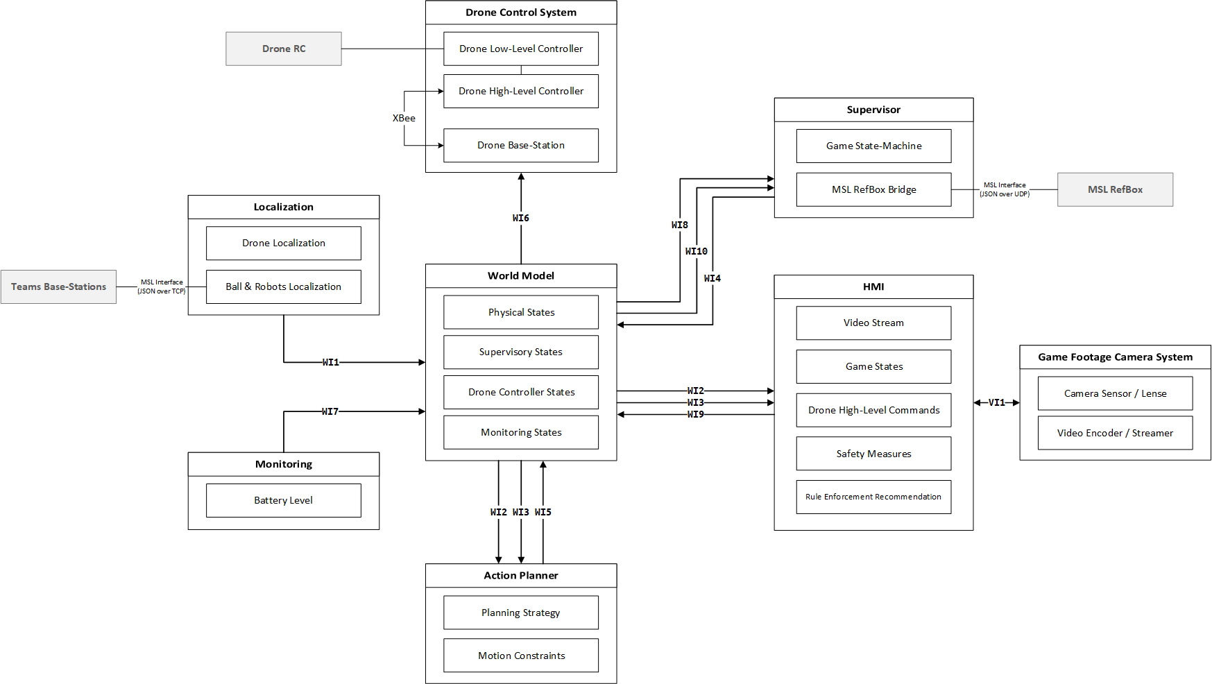
World model
Functions:
- Acts as system’s model, avoiding lateral dependencies between sub-systems,
- State storage for the whole system,
- Master message-passing node for sub-systems,
- Single logging point of the system.
Camera footage system and HMI
Supervisor
Supervisor Introduction The supervisor is a subsystem of RAS. This subsystem is responsible for providing high level control states for the other subsystems of RAS. Furthermore, it is responsible for translating user commands to states. The supervisor subsystem monitors the overall safety of RAS. Architecture constraints • RAS: The supervisor subsystem is responsible for keeping record of the states of RAS. The supervisor must capture the game, before game, emergency situation in its states. The states of the supervisor must be accessible to other subsystems of RAS
• Drone MSL: Supervisor states must include drone positioning as additional states. Supervisor must include drone emergency situations in its states. Supervisor states are independent on MSL sub-packages (2d, gimbal, inclined?) Supervisor takes input from MSL referee box through json interface. Supervisor takes land, take off, safe to land from remote referee through world model Supervisor gives the high level game states as outputs through world model Supervisor enabled the RR to land from any point in the field. Supervisor enables the drone to take off after takeoff command receive from RR. Supervisor enable the drone to start refereeing the game after receiving the start game signal form MSL referee box. Supervisor dictates that after a half time ends drone will hover above landing position. Supervisor dictates that after receiving the land command drone will hover above landing position. Supervisor enables the landing of the drone after checking it safe to land from both RR and drone action planner. State transition: check with AP requirements.
System description In this section, a description of the supervisor subsystem for the MSL 2D architectural package will be shown. The description is divided into four points. These points are scenarios, purpose, inputs and outputs. Scenarios In the upcoming sub-section, selected game operation scenarios are presented. The purpose of these scenarios is to show the sequence of events of running game. These sequences are the result of application of the requirements or constraints to our drone referee system. In the next part, we will try to use these scenarios to obtain supervisory states for our MSL 2D architectural package. These scenarios are game, intentional landing and emergencies scenarios. Game scenario This scenario shows a complete sequence for the first half time of a MSL 2D game. The step sequence is the following: 1. RR makes sure robot players are positioned in center. 2. RR press take off using HMI. 3. Drone takes off then flies to start position. For MSL 2D ,the start position is the center of the pitch. 4. Drone is hovering at start position. 5. MSL referee issues start game signal. 6. Game starts. 7. Drone starts the refereeing technique. 8. First half time is over. 9. MSL referee issues the end of the 1st half time signal. 10. Drones hovers above landing position. 11. RR presses it is okay to land in HMI. 12. Drone lands in the landing position. 13. Drone is waiting for another game start. Intentional land scenarios These scenarios represent situations where the RR wants to land the drone before and during game. In this document, two scenarios are shown. The first scenario (ILS1) ,where; the RR wants the drone to land before game start. While, the second one (ILS2), where, RR wants the drone to land during the game. The sequence of steps of ILS1 is: 1. RR makes sure robot players are positioned in center. 2. RR press take off using HMI. 3. Drone takes off then flies to start position. For MSL 2D ,the start position is the center of the pitch. 4. Drone is hovering at start position. 5. RR presses land in HMI. 6. Drones hovers above landing position. 7. RR presses it is okay to land in HMI. 8. Drone lands in the landing position. 9. Drone is waiting for another game start. While, the steps for ILS2 are: 1. RR makes sure robot players are positioned in center. 2. RR press take off using HMI. 3. Drone takes off then flies to start position. For MSL 2D ,the start position is the center of the pitch. 4. Drone is hovering at start position. 5. MSL referee issues start game signal. 6. Game starts. 7. Drone starts the refereeing technique. 8. RR presses land in HMI. 9. Drones hovers above landing position. 10. RR presses it is okay to land in HMI. 11. Drone lands in the landing position. 12. Drone is waiting for another game start. Drone Emergencies scenarios In these scenarios, three sets of sequences are presented. These sequences deal with only one kind of emergency. This emergency is related to battery emergency at different moments the game. These moments are before game start and drone is still in land (EMS1), drone is hovering at center before game start (EMS2) and during game (EMS3). The sequence of steps of EMS1 is: 1. Before game, drone is on land 2. Drone emergency occurs 3. Drone is not able to takeoff despite any command given by RR 4. Drone will only be able to take off again only when emergency is solved For EMS2, the sequence is : 1. RR makes sure robot players are positioned in center. 2. RR press take off using HMI. 3. Drone takes off then flies to start position. For MSL 2D ,the start position is the center of the pitch. 4. Drone is hovering at start position. 5. Drone emergency occurs 6. Drone lands 7. Drone is not able to takeoff despite any command given by RR And for EMS3, the sequence is: 1. RR makes sure robot players are positioned in center. 2. RR press take off using HMI. 3. Drone takes off then flies to start position. For MSL 2D ,the start position is the center of the pitch. 4. Drone is hovering at start position. 5. MSL referee issues start game signal. 6. Game starts. 7. Drone starts the refereeing technique. 8. Drone emergency occurs 9. Drone lands 10. Drone is not able to takeoff despite any command given by RR 11. Drone will only be able to take off again only when emergency is solved Functions From the previous scenarios and constraints, the functions of the sub-system supervisor can be presented by these points: • To take the remote referee’s commands, referee box game states and drone emergency as inputs • To provide high level control ( game) states according to inputs. • To provide reaction to emergency situations The other sub-systems will take action based on the high level abstract states. In figure , a context diagram for the supervisor subsystem is depicted. In this diagram, the inputs and outputs of the system are shown. Furthermore, the possible messages for each input or output are shown. In the figure, the system boundary line separates the subsystems of the drone referee form the outside environment.

Output High level control (game) states: Supervisor write these states into world model. Other subsystems like action planner read these states and take action based on them. Design choices For the MSL 2D, the supervisor will have 5 states. The transition between these states are governed by transition conditions. These conditions are based on the values and combinations of the so called transition variables and the transition variables are based on the inputs of the supervisor subsystem. States The 5 states of the supervisor are presented in table 1. Furthermore, table 1 shows the description of each state.
Table 1 State description States Description States Description S1 “Pre-game” Before game Drone is on land Drone is in landing position No Emergency is detected S4 “Terminating” Game can be running or game end Drone is hovering Drone is on landing position No Emergency is detected S2 “Game prep” Before game Drone is hovering Drone is in center No Emergency is detected S5 “Emergency land” Can be before, during or after game Drone is on land Drone is in landing position Emergency is detected S3 “Game run” Game is running Drone is following refereeing strategy Drone is inside field No Emergency is detected
Transition variables In table 2, the description, value, condition of each transition variable are shown. Table 2 Transition variable description Transition variables Description Transition variables Description E1
Takeoff E1 = 1, when takeoff is pressed.
E1 = 0, when takeoff is not pressed. E4 Safe to land from HMI E4 = 1, when safe to land is pressed. E4 = 0, when safe to land is not pressed. E2 Game start, Game end E2 = 1, when game is started. E2 = 0, when game is not started. E5 Safe to land from Action planner E5 = 1, when safe to land is pressed. E5 = 0, when safe to land is not pressed. E3 Land E3 = 1, when land is pressed. E3 = 0, when land is not pressed. Em Emergency status Em = 1, when emergency is reported. Em = 0, when emergency is not reported.
Transition conditions They are conditions consisting of the variables and mathematical operators. The operators are || (OR) , == (EQUALS) and && (AND). Whenever, the condition is true, the supervisor is allowed to move from the current state to the future one. Tables 3 shows the description of each condition, the current state and the future sate.
Table 3 Transition conditions Transition number Condition Description Current state Future state if condition is satisfied C1 [E1 == 1] Take off is pressed. S1 S2 C2 [E2 == 1 ] game is started. S2 S3 C3 [E3 == 1] land is pressed. S2 S4 C4 [E2 == 0 || E3 == 1] land is pressed or game is ended S3 S4 C5 [E5 == 1 && E4 == 1] Safe to land from action planner and HMI S4 S1 C6 [Em == 1] Emergency is reported. S1 S5 C7 [Em == 1] Emergency is reported. S2 S5 C8 [Em == 1] Emergency is reported. S3 S5 C9 [Em == 1] Emergency is reported. S4 S5 C10 [Em == 0] Emergency is resolved. S5 S1
State machine The complete state machine of the supervisor subsystem is shown in figure 2. The initial state of the system is S1. In the figure, the states, variables and conditions are shown. Furthermore, the output (high level control (game) states) of the supervisor is presented in the variable game_state. This variable is sent to world model and can be read by other subsystems.
Figure 2 State machine of the supervisor subsystem Reaction to emergency situations In MSL 2D, there are two emergency situations. The first one is drone emergency. While, the second one is dependent on the remote referee’s estimation. For both of these situations, the drone will land. Assumptions • RR must make sure that robots are in starting place while drone is hovering above starting position. • RR must make sure that is safe to takeoff before pressing safe to take off in HMI. • The drone emergency situations considered in the systems are only battery emergencies. • RR must make sure there are no obstacles in the airfield and landing position. • RR must make sure the safety net is closed. • During game pauses drone will still follow the refereeing strategy. • System’s initial state is always at S1 Technology For this supervisor, Matlab Stateflow was used [add ref].
Recommendations Emergency situations Supervisor should consider other drone emergency situations. These situations can be obtained after experimentation of the system in several test runs. Furthermore, additional functional safety measures could be considered for each subsystem. Model based supervisor It was not possible for our team to model each subsystem separately and make maximal permissive supervisor with the time resources we had. Furthermore, the drone manufacturer used Matlab Simulink to control the drone. Designing a maximally permissive supervisor on Matlab is very difficult. Our recommendation is to model the subsystems using other supervisory control tools. After finishing the supervisor start couple it with Matlab. The challenge in this case would be modeling, capturing requirements and supervisor synthesis. [ add ref]
Action planner
Localization systems
MSL/Ball-Following Gimbal
MSL/Ball-Following Gimbal CAFCR
MSL/Ball-Following Gimbal use case
MSL/Ball-Following Gimbal context diagrams
Project Management
Introduction
Project management plan
Communication management plan
Quality management plan
Test management plan
Risk analysis
Simulation
Introduction
Architecture constraints
System description
Interface (I/O) descriptions
Component descriptions
- 2-D
- Gimbal
Design choices
Technology
Implementation
Drone
Introduction
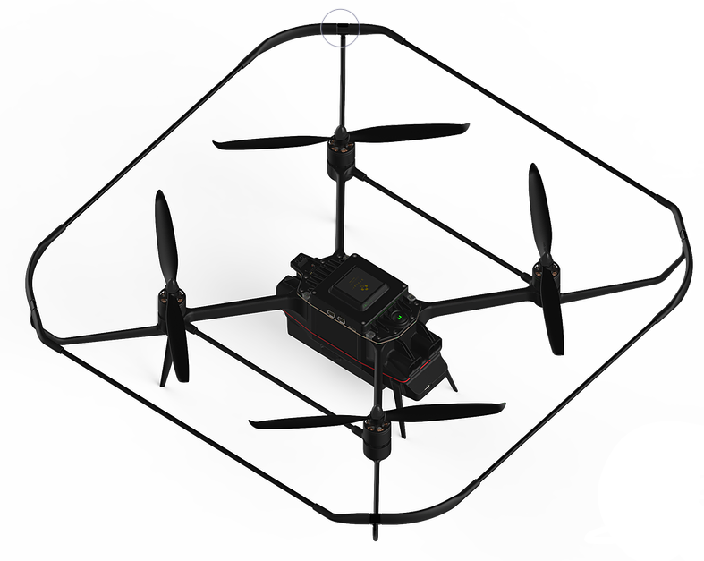
The drone is the main hardware subsystem of the RAS. This subsystem includes sensors, microcontroller, communication ports and mechanical components. The drone used in this project, is the last version of Avular curiosity drone provided by Avular company. The drone can be programmed by means of Matlab Simulink. All the other subsystems must eventually be implemented on the drone to achieve the final goal of game refereeing.
Architecture constraints
*RAS:
The drone must be able to fly autonomously.
The drone is responsible to follow the command of action planner through world model
The sensors data must be accessible to world model (the other subsystem of RAS)
The drone should provide the battery level information to other subsystems.
The drone must have the possibility of installing the footage camera on it.
*Drone MSL:
The drone must be able to fly for 5+2 minutes and show the battery level all the time.
System description
The drone is the main hardware subsystem of drone referee system which consists of different components and subsystems itself. The main task of the drone is to receive commands in real time from a remote computing module (usually a PC) and follow the action required from action planner while carrying the footage camera. For this need,the main challenge is programming the drone and setting the wireless connection for sending wireless data to the microcontroller present on the drone. There are three main computation modules called “Low-Level Module”, “High-Level Module” and “Compute Module”. Each one of the Low-Level, High-Level, and Compute Modules is connected to a different set of sensors, actuators or communication devices. The idea is to use Low-Level Module for calculations related to flight stabilization and monitoring the current status of the drone, and use the High-Level Module for other high-level calculations (such as path planning or position control of the drone) which can be different depending on the project requirements. For projects that require intensive computations, the Compute Module can also be used in combination with both High-Level and Low-Level Modules. Each one of the High-Level and Low-Level Modules uses one 180MHz Cortex-M4 processor and the Compute Module is a Raspberry-Pi Compute Module 3.
Design choices
Subsystem results (demo)
World model
- Binary serialization of data for each interface,
- Uses UDP for sending/receiving information for each interface,
- Implemented in Simulink,
- Simulink and C# clients are implemented.


