Embedded Motion Control 2018 Group 5: Difference between revisions
| (228 intermediate revisions by 4 users not shown) | |||
| Line 65: | Line 65: | ||
Here, the functions that will be implemented in the software of PICO are presented. The functions are split up in different categories, namely Task, Skill, Action and World model. | Here, the functions that will be implemented in the software of PICO are presented. The functions are split up in different categories, namely Task, Skill, Action and World model. | ||
'''Task:''' Contains the main goal that the robot needs to | '''Task:''' Contains the main goal that the robot needs to fulfil. For the first challenge this is escaping the room. For the second challenge this is mapping the hospital, parking backwards and subsequently finding an object. | ||
* Escape a room | * Escape a room | ||
* Mapping | * Mapping | ||
| Line 137: | Line 137: | ||
==Interfaces== | ==Interfaces== | ||
=Escape room Challenge= | {| class="infobox" style="width:378px" | ||
In the Escape room | |rowspan=1 style="text-align:center;" |[[File:Interface Diagram.png|center|700px]] | ||
|- | |||
|colspan=1 style="text-align:center;" |'''Figure 1: Interface diagram''' | |||
|} | |||
='''Escape room Challenge'''= | |||
In the Escape room challenge PICO was placed on an arbitrary location in a rectangular room from which it had to escape through a corridor. This had to be done as fast as possible. | |||
==Wall follower== | ==Wall follower== | ||
In order to complete this challenge, a so-called Wall follower algorithm was built and implemented. The steps that the algorithm makes in order to complete the challenge are as follows: | In order to complete this challenge, a so-called Wall follower algorithm was built and implemented. The steps that the algorithm makes in order to complete the challenge are as follows: | ||
* Drive to the right until a wall is detected at the right side | * Drive to the right until a wall is detected at the right side. | ||
* Follow this wall by driving forward until a wall is detected | * Follow this wall by driving forward until a wall is detected. | ||
* If the distance to the right wall becomes larger than a predefined threshold, compensate by driving sideways to the wall | * If the distance to the right wall becomes larger than a predefined threshold, compensate by driving sideways to the wall. | ||
* When a corner is detected ahead, rotate 90 degrees to the left and align to the wall perpendicular to the previous wall | * When a corner is detected ahead, rotate 90 degrees to the left and align to the wall perpendicular to the previous wall. | ||
* If the corridor is detected by an increase in distance measured at the wall side (defined by a certain threshold), PICO will drive another 25 cm forward and then rotate 90 degrees to the right | * If the corridor is detected by an increase in distance measured at the wall side (defined by a certain threshold), PICO will drive another 25 cm forward and then rotate 90 degrees to the right. | ||
* PICO will drive forward and then align to the right wall again, allowing it to exit the room. | * PICO will drive forward and then align to the right wall again, allowing it to exit the room. | ||
For detection, PICO uses sensor-data of the sensors located perpendicular to its forward driving direction. These sensors are used to find the distance to walls at its left and right side, defined as ''LeftDistance'' and ''RightDistance'' respectively. The sensor that is aligned with the forward driving position is used to find the distance | For detection, PICO uses sensor-data of the sensors located perpendicular to its forward driving direction. These sensors are used to find the distance to walls at its left and right side, defined as ''LeftDistance'' and ''RightDistance'' respectively. The sensor that is aligned with the forward driving position is used to find the distance to a wall that is in the forward driving direction, defined as ''ForwardDistance''. The detection of a corner as described in step 5 is done by looking at ''ForwardDistance'' and ''RightDistance''. When both of these distances become lower than a predefined threshold, a corner must be present at the right side, and therefore, PICO should rotate to the left. By using this algorithm, PICO is able to find the corridor of the room and escape the room. | ||
=== Testing === | === Testing === | ||
The testing sessions with PICO were used for testing the algorithm and fine tuning some parameters in the model, such as velocities, rotational velocities and required minimal distances to walls. During the testing, it was found that there is a large difference between the simulation and reality. First, it was concluded that the odometry of PICO should not be trusted too much for localization and moving around. This could be noticed at the 90 degrees rotation that was used. The actual rotation PICO made had a noticeable offset. A possible solution to this problem was using the wall at the side to determine if PICO is aligned with the wall by using additional sensor data. This solution was implemented and tested in the simulation. In the simulation, the solution worked quite well for making the corners, but it also caused some unexplainable and unwanted behaviour. Due to a lack of time, no solution to this problem could be found and therefore, this was not implemented for the Escape room challenge. Another flaw that occurred during testing was that PICO did not always detect the wall at its right side in step 1, and because of this, PICO hit the wall. This did not happen in any of the simulations, and it remains unclear why this happened during testing. Despite these two problems, PICO was able to get out of the room once during testing. | The testing sessions with PICO were used for testing the algorithm and fine tuning some parameters in the model, such as velocities, rotational velocities and required minimal distances to walls. During the testing, it was found that there is a large difference between the simulation and reality. First, it was concluded that the odometry of PICO should not be trusted too much for localization and moving around. This could be noticed at the 90 degrees rotation that was used. The actual rotation PICO made had a noticeable offset. A possible solution to this problem was using the wall at the side to determine if PICO is aligned with the wall by using additional sensor data. This solution was implemented and tested in the simulation. In the simulation, the solution worked quite well for making the corners, but it also caused some unexplainable and unwanted behaviour. Due to a lack of time, no solution to this problem could be found and therefore, this was not implemented for the Escape room challenge. Another flaw that occurred during testing was that PICO did not always detect the wall at its right side in step 1, and because of this, PICO hit the wall. This did not happen in any of the simulations, and it remains unclear why this happened during testing. Despite these two problems, PICO was able to get out of the room once during testing. | ||
=== The Challenge === | |||
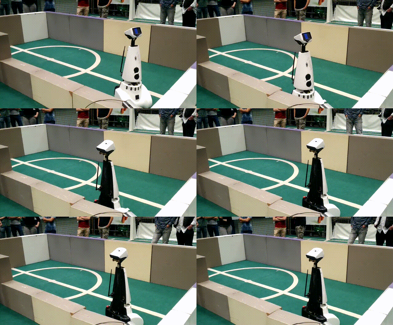
During the challenge, the second problem that was discussed above obstructed PICO from finding the exit. PICO failed to detect the wall at its right side and drove into it, which is shown in Figure 2 below. Unfortunately, this happened at both trials. After evaluation of the Escape room challenge, it was concluded that a different approach was required for the Hospital Challenge. This means that from this point on, the Wall follower algorithm is abandoned and a new a plan for a new approach is made. | |||
=== | {| class="infobox" style="width:800px" | ||
|rowspan=1 style="text-align:center;" |[[File:EscapeRoomChallengeGroup5.gif]] | |||
[[File:EscapeRoomChallengeGroup5.gif|center| | |- | ||
|colspan=1 style="text-align:center;" |'''Figure 2: PICO during the escape room challenge''' | |||
|} | |||
===Conclusion=== | ===Conclusion=== | ||
A relatively simple algorithm was made for the Escape room challenge, which finds and then follows the wall at its right side until it detects the exit. Based on simulations, this algorithm was sufficient for completing the Escape room challenge. However, during testing, multiple differences were observed between the simulation and reality. It is learned that navigating using purely PICOs odometry is overall not a smart strategy, and therefore this strategy will no longer be used from this point. Hitting | A relatively simple algorithm was made for the Escape room challenge, which finds and then follows the wall at its right side until it detects the exit. Based on simulations, this algorithm was sufficient for completing the Escape room challenge. However, during testing, multiple differences were observed between the simulation and reality. It is learned that navigating using purely PICOs odometry is overall not a smart strategy, and therefore this strategy will no longer be used from this point. Hitting a wall due to a detection error was the reason the Escape room challenge ended premature for PICO, the exact cause of this error has not been found. This is however not an issue for the final challenge, because the next step is going back to the drawing table and come up with a new plan. | ||
='''Hospital Challenge'''= | |||
The second and final challenge is the Hospital Challenge. In this challenge, PICO has to find an unknown object in a hospital environment which consists of a hallway and multiple rooms. After the Escape Room Challenge a new plan is made to successfully complete the Hospital Challenge. This plan consists of three phases: mapping the hospital, parking against the wall and finding the object. During these phases, PICO needs skills such as world mapping, localization, path planning and object detection. Furthermore, PICO needs to be able to move through the hospital without hitting any of the walls. How the mapping, parking and object detection are performed and how these functions are implemented is explained here. | |||
= | {| class="infobox" style="width:500px" | ||
|rowspan=1 style="text-align:center;" |[[File:architecture_5.png|center|550px]] | |||
|- | |||
|colspan=1 style="text-align:center;" |'''Figure 3: Overview of the software architecture''' | |||
|} | |||
==World mapping== | ==World mapping== | ||
In the first phase of the challenge, PICO has to make a map of the environment. To accomplish this, | In the first phase of the challenge, PICO has to make a map of the environment. To accomplish this, an external library called MRPT ([https://www.mrpt.org/ Mobile Robot Programming Toolkit]) is used. This library contains some useful classes, that help us to efficiently program the software required for PICO to accomplish its task. The first task is to process the laser range data of PICO. The class ''CObservation2DRangeScan'' is used, which takes as input a vector with range data, a binary validity vector and the aperture of the range scan. The validity vector is used to consider which data points are valid to for example filter out the outer data points which contain a significant amount of noise. The ''CObservation2DRangeScan'' object is inserted in a second class, the ''CSimplePointsMap''. Each valid point is inserted into the map which contains the 2D coordinates of the points where the laser range finder detected a wall. The first set of data is used to create a points map for the world map. Now of course the world map needs to be updated with the new measurements. A second ''CSimplePointsMap'' object is created to store the current range data of PICO. Then an iterative closest point algorithm (Levenberg-Marquardt) , implemented in the CICP class [7], is used to fit the points of the world map and current view to each other. It takes the current position as initial guess for the fitting and tries find the optimal pose between the map of the current view and reference worldmap. From the displacement and rotation of the current view with respect to the world map, the location and rotation of PICO is obtained with respect to its starting position. This way both PICO’s position and world map are continuously updated. The map can be output as a bitmap image and can be used to recognize the location of the rooms and doors. | ||
==Path planning== | ==Path planning== | ||
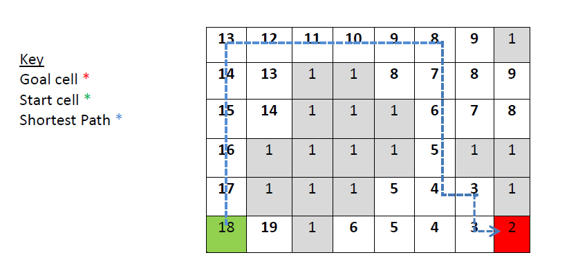
For the navigation of PICO | For the navigation of PICO, the path planning algorithm implemented in the ''PlannerSimple2D'' class is used. It uses a wave front algorithm to find the shortest path between position and target. An example of the wave front algorithm is shown in Figure 4 below. Like in many other path planning algorithms, the wave front algorithm uses a grid map for processing. Because of this, the ''PlannerSimple2D'' class only takes a grid map in the form of a ''COccupancyGridMap2D'' object as input and therefore the points map is first converted to a grid map object. Each point from the world map is inserted in the ''COccupancyGridMap2d'' object, which based on input of the maximum x- and y-range determines which cells are occupied and which not. The grid map is inserted in the ''PlannerSimple2D'' class to compute the desired path. The path planner object also contains the value for the radius of the robot. It enlarges the walls by this radius to make sure the found path does not intersect with the walls. The path is returned as a set of points with a given step size, which can then be used for navigation. | ||
== | {| class="infobox" style="width:378px" | ||
|rowspan=1 style="text-align:center;" |[[File:wavefront_algorithm.png|600px]] | |||
|- | |||
|colspan=1 style="text-align:center;" |'''Figure 4: Example of the wave front algorithm. Obstacles are denoted by a 1 and the origin is denoted by 2. Each 'open' cell surrounding the origin is denoted by 3. This is repeated for the remaining of the open cells, like a wave propagating trough the gridmap, until the target is reached. The sum of the path is then minimized to find the shortest path from origin to target.''' | |||
|} | |||
In phase 1, PICO will be building a map of the hospital by using the | ==Phase 1: Mapping the hospital== | ||
In phase 1, PICO will be building a map of the hospital by using the world mapping and path planner as described above. Once this is done, PICO will return to its starting position and park there. Next to this, PICO will use the map for defining rooms and doors in the hospital. These features are further explained here. | |||
===Initialize map=== | ===Initialize map=== | ||
At the start, PICO will be placed at an arbitrary angle with respect to the hospital walls. In the "Initialize map" phase, PICO uses the initial view to compensate this arbitrary starting angle. In order to do this, the data from the first measurement of laser data is used to determine the angle of PICO with respect to the walls in the hallway. The initial view and initial angle are then used to initialize the world map and correct the rotation of the world map so that the walls are parallel with the x- and y-axis. In order to clarify the result of this initialization a bit more, the situation before and after the initialization is shown in Figure 5. A [[#Part of the code| code snippet]] of the determination of the initial angle is given. | |||
At the start, PICO will be placed at an arbitrary angle with respect to the hospital walls. In the "Initialize map" phase, PICO uses the initial view to compensate this arbitrary starting angle. In order to do this, data | |||
[[File:Initialization.png| | {| class="infobox" style="width:378px" | ||
|rowspan=1 style="text-align:center;" |[[File:Initialization.png|250px]] | |||
|- | |||
|colspan=1 style="text-align:center;" |'''Figure 5: Initialization of the worldmap''' | |||
|} | |||
===Building the map=== | ===Building the map=== | ||
The World Mapping algorithm and the Path planning algorithm are combined in order to map the hospital. The path planning algorithm is provided with a setpoint that is located outside the hospital. The setpoint is positioned sufficiently far away guaranteeing that it will be located outside the hospital. The | The World Mapping algorithm and the Path planning algorithm are combined in order to map the hospital. The path planning algorithm is provided with a setpoint that is located outside the hospital. The setpoint is positioned sufficiently far away guaranteeing that it will be located outside the hospital. The path planning algorithm will compute a path to the setpoint and PICO will follow this path while scanning its environment and creating the map. While following the path, the hospital will be further explored and the path will be blocked by the walls that are detected. The path planning algorithm will continuously compute a new path to the given setpoint taking the known map into account and thus finding a way around the detected walls. The path following is repeated, until no path can be found towards the setpoint. This means that the contour of the hospital is closed and all rooms have been visited. At this point, PICO will return to its starting position to initiate the parking against the wall. In Figure 6, a simulation of the mapping procedure is shown. A [[#Part of code| code snippet]] on how the worldmap is updated is given. | ||
{| class="infobox" style="width:378px" | |||
|rowspan=1 style="text-align:center;" |[[File:fullrun.gif]] | |||
|- | |||
|colspan=1 style="text-align:center;" |'''Figure 6: Simulation in which PICO is building a map of a hospital''' | |||
|} | |||
===Parking=== | ===Parking=== | ||
Once the map of the hospital is finished, PICO will start the parking phase. The path planner will plan a path back to the starting position based on the world map that is made. After arriving at the starting position, PICO will rotate to an angle of 180 degrees, such that it is facing the wall it will park against. The frontal distance to the wall is measured and PICO will rotate back to an angle of 0 degrees, such that it faces the wall backwards. | |||
Once the map of the hospital is finished PICO will start the parking phase. The path planner will | |||
PICO will start driving backwards with a reduced speed, for the distance it measured, until it touches the wall. For extra robustness, PICO will make use of the control effort data, so that it stops driving backwards once it touches the wall and the control effort output reaches a certain threshold. PICO is now parked and ready to find the object! The parking phase of PICO is shown in Figure 7 below. | |||
{| class="infobox" style="width:378px" | |||
|rowspan=1 style="text-align:center;" |[[File:Parking.gif]] | |||
|- | |||
|colspan=1 style="text-align:center;" |'''Figure 7: PICO in the Parking phase''' | |||
|} | |||
===Define rooms=== | ===Define rooms=== | ||
With the use of the worldmap rooms and doors are located. To locate the rooms first a set of image adjustments are performed on the worldmap, with the use of | With the use of the worldmap, rooms and doors are located. To locate the rooms, first a set of image adjustments are performed on the worldmap, with the use of ''opencv''. First the image is processed using erosion.[1] With the erosion process the walls in the image are thickened until the hallway and doors are all filled. This results in white spaces that represent a piece of the rooms, see Figure 8. In the processed image the contours are found using the opencv function ''findContours'' which is able to find contours in a binary image. [3]. The function is set to construct a full hierarchy of nested contours, i.e. of the contours the children and parent contours are known. This is necessary since the largest contour is represents the entire hospital, the parent contour, and this is not of interest. For the contours of the rooms the moments are calculated using Green’s formula [6]: | ||
<math>m_{ji}= \sum_{x,y}(array(x,y) \cdot x^j \cdot y^i)</math>. | <math>m_{ji}= \sum_{x,y}(array(x,y) \cdot x^j \cdot y^i)</math>. | ||
| Line 210: | Line 235: | ||
<math>\bar x = \frac{m_{10}}{m_{00}},\qquad \bar y=\frac{m_{01}}{m_{00}} </math> | <math>\bar x = \frac{m_{10}}{m_{00}},\qquad \bar y=\frac{m_{01}}{m_{00}} </math> | ||
In Figure | In Figure 8 an example is given for the contours and center points. A [[#Part of code| code snippet]] is given. | ||
{| class="infobox" style="width:378px" | |||
|rowspan=1 style="text-align:center;" |[[File:contours.png|250px]] | |||
|- | |||
|colspan=1 style="text-align:center;" |'''Figure 8: Midpoints and contours of simulation''' | |||
|} | |||
===Locate doors=== | |||
After the world map is obtained, the inside of the hospital is marked by coloring the pixels. The walls and the surroundings of the hospital are marked with a different color. To be able to do this, the inside of the hospital needs to be surrounded by a closed contour, so no gaps are allowed in the walls of the hospital. This is achieved by using a combination of the opencv functions ''erode'' and ''findContours''.[1][3] The function ''erode'' thickens lines and pixels in any direction. This is applied until all the gaps in the walls are closed, doors and hall way remain open. Subsequently, the function ''findContours'' can now find the closed contour which surrounds the inside of the hospital. Now the inside of the hospital can be marked and it surroundings can be marked with a different colour, see Figure 9.a. | |||
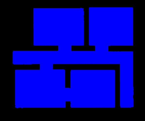
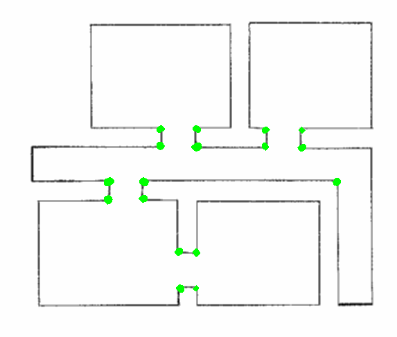
Using the opencv function ''cornerHarris'' [2] all corners of the hospital are detected. Subsequently, two types of corners are distinguished, namely corners that cover 90 degrees or 270 degrees of the inside of the hospital. Only the corners that are 270 degrees are used for further analysis, see Figure 9.b. The set of corners that are 270 degrees are sorted in vertical and/or horizontal pairs only if they are 1.5 m apart or less and either the x-coordinate (vertical pair) or the y-coordinate (horizontal pair) is (approximately) the same. | |||
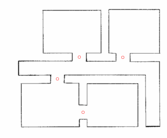
To find doors that consist of 4 corners, the vertical pairs of two are sorted in quartets only if the y-coordinates of the two pairs are aligned such that together they could form a door. Subsequently, it is checked if the whole space in between the 4 corners of each quartet is marked as the inside of the hospital. If this is the case it is also checked if at least on the right or top of the so called door the pixels are marked as wall or surrounding. The latter is done to ensure that open spaces in between two doors that in front of each other are not detected as a door as well. If both requirements are fulfilled a 4 corner door is found. In Figure 9.c can be seen that the door detection works for the possible hospital map that was provided. A similar procedure was thought of for doors consisting of 2 corners. For vertical pairs it is checked if either left or right of the pair the pixels are marked as wall or surrounding. Suppose that on the right size of the vertical pair the pixels are marked as wall or surrounding, then the width of the door is determined by finding the nearest wall to the left of this vertical pair. For horizontal pairs it is checked if either above or below of the pair the pixels are marked as wall or surrounding and the width of the door is determined by finding the nearest wall to the top or bottom of this horizontal pair. | |||
''' | {| class="infobox" style="width:750px" | ||
|rowspan=1 |[[File:filled.png|250px]] | |||
|[[File:corners.png|250px]] | |||
|[[File:doors.png|250px]] | |||
|- | |||
|colspan=1 style="text-align:center;" |'''Figure 9.a: Marking the inside and outside of the hospital in simulation''' | |||
|colspan=1 style="text-align:center;" |'''Figure 9.b: Detecting 270 degrees corners in simulation''' | |||
|colspan=1 style="text-align:center;" |'''Figure 9.c: Doors in simulation''' | |||
|} | |||
When a door is located it is key that the pixels which are identified as the door opening are calculated. Combining this information with the center points of the rooms the hint can be used. The path planner is asked to plan a path to the center point of a room. When the path is know it can be checked through how many door openings the path goes to get to the room. When this is applied for all rooms it can be calculated for which room the most doors must be passed to get to it and the room in which the object is found. | |||
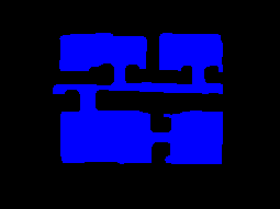
''' | Unfortunately, since the opencv function ''erode'' might need some manual tuning for the amount of erosion it was considered unreliable. In Figure 10.a the result of successful erosion can be seen for a world map of real (non-simulated) laser data after tuning the settings manually. Furthermore, erosion on a less perfect real-life map had as a consequence that corners of rooms get misshaped and can no longer be detected by the opencv function ''cornerHarris'', see Figure 10.b. Therefore it was decided to not implement this part for the final challenge. | ||
{| class="infobox" style="width:500px" | |||
|rowspan=1 |[[File:filled_real.png|250px]] | |||
|[[File:corners_real.png|250px]] | |||
''' | |- | ||
|colspan=1 style="text-align:center;" |'''Figure 10.a: Marking the inside and outside of the hospital of the final challenge''' | |||
|colspan=1 style="text-align:center;" |'''Figure 10.b: Detecting 270 degrees corners of the final challenge''' | |||
|} | |||
==Phase 2: Finding the object== | ==Phase 2: Finding the object== | ||
| Line 242: | Line 280: | ||
===Connection diagram=== | ===Connection diagram=== | ||
With the known locations of the rooms and doors a connection diagram can be drawn, see Figure | With the known locations of the rooms and doors a connection diagram can be drawn, see Figure 11. In this diagram the connections between the rooms and the hallways are drawn. For example, if one is standing in the hallway and would want to visit room 4 it has to pass through room 3 first. | ||
[[File:Afbeelding1.png| | {| class="infobox" style="width:450px" | ||
|rowspan=1 style="text-align:center;"|[[File:Afbeelding1.png|250px]] | |||
|- | |||
|colspan=1 style="text-align:center;" |'''Figure 11: Room connection diagram ''' | |||
|} | |||
To connect the doors to the right room, the path planning algorithm is used. For every room the shortest path from the origin is planned. An iteration over the setpoints of the path is made and it is checked if the setpoints lie in the contour of the four points of the doors, by means of the opencv’s function pointPolygonTest. If a setpoint lies in the contour of a door, it means the door must be passed through in order to reach the room from the origin. The number of doors that are passed through are counted and the room that needs the most doors to be passed through is passed through to the find-object phase. It is taken into account that a door can be passed through only once in every path, i.e. if more setpoint of a single path lie in the contour of the same door, the door is only counted once. | To connect the doors to the right room, the path planning algorithm is used. For every room the shortest path from the origin is planned. An iteration over the setpoints of the path is made and it is checked if the setpoints lie in the contour of the four points of the doors, by means of the opencv’s function ''pointPolygonTest''.[4] If a setpoint lies in the contour of a door, it means the door must be passed through in order to reach the room from the origin. The number of doors that are passed through are counted and the room that needs the most doors to be passed through is passed through to the find-object phase. It is taken into account that a door can be passed through only once in every path, i.e. if more setpoint of a single path lie in the contour of the same door, the door is only counted once. | ||
===Object detection=== | ===Object detection=== | ||
[ | For PICO to complete the find object phase it has to stop near the object; Therefore, only using the high-level hint is not enough. While driving to the target room, PICO starts it object detection phase. In this phase PICO constantly compares the map of the hospital, made in the mapping phase, with the current updated map by subtracting the maps from each other. The result is a map where only differences are visible. | ||
Since both the map made in the mapping phase and the current map can have noise in it, the noise must be filtered and not be confused for the object. For the difference map all the contours are computed (findContours [3]) and only the largest contour is checked, i.e. the largest difference. For the largest difference in the map the bounding rectangle is calculated using opencv’s ''boundingRect'' [5], i.e. a rectangle that fits the contour. If this rectangle has dimensions larger than a predetermined minimal height and width, the rectangle is identified as the object and the coordinates of the object are saved. If the rectangle does not suffice for the predetermined dimensions, the routine of comparing the current map with the hospital map is repeated. | |||
When PICO has identified the object the path planning algorithm computes a path to the object and PICO is to follow the path until it is at a minimal set distance of the object. Once it is at the object location, PICO stops driving and will speak: “I have found the object”. A video of PICO successfully finding an object and the corresponding OpenCV processing are shown below. A [[#Part of code| code snippet]] of the object detection is given. | |||
{| class="infobox" style="width:378px" | |||
|rowspan=1 style="text-align:center;" |[[File:FoundObject.gif]] | |||
|- | |||
|colspan=1 style="text-align:center;" |'''Figure 12: PICO finding and driving towards the object.''' | |||
|- | |||
|rowspan=1 style="text-align:center;" |[[File:object_detection.gif]] | |||
|- | |||
|colspan=2 style="text-align:center;" |'''Figure 13: Comparing two maps for differences and object detection.''' | |||
|} | |||
==The Challenge== | ==The Challenge== | ||
[ | During the hospital challenge PICO was able to successfully map the hospital and park backwards. PICO moved at a slow pace but because of the path planning algorithm, used to map the hospital, PICO was able to map the hospital quickly. The map of the hospital is given in the Figure 14.a. Besides the rooms and hallway of the hospital some noise was measured outside the hospital. This is due to the readings of the LRF over the walls. With the complete map PICO was able to plan a path back to its origin and park backwards. | ||
After the hospital map was completed, the map was post processed as explained in [[#Define rooms| Define rooms]] to find the rooms. The noise mapped outside the hospital was not off influence on the detection. The rooms that were detected are illustrated in Figure 14.b. | |||
{| class="infobox" style="width:378px" | |||
|rowspan=2 |[[File:gridmap.png|250px]] | |||
|- | |||
|[[File:Hospital_midpoints.png|250px]] | |||
|- | |||
|colspan=1 style="text-align:center;" |'''Figure 14.a: Worldmap created during the challenge''' | |||
|colspan=1 style="text-align:center;" |'''Figure 14.b: Midpoints and contours of hospital challenge''' | |||
|} | |||
During the challenge, the door detection was not yet implemented as described in [[#Locate doors| Locate doors]]. Therefore, the hint was not implemented. In the object detection phase PICO was set to drive towards the midpoints of the detected rooms in random order to search for the object. During the two official tries the localization of the object failed. As can be seen from the worldmap in Figure 14, there is a lot of noise at the bottom and top of the map. Because the walls on these sides were just not high enough, PICO was able to see over the walls a little and able to observe the people outside the staging area. During the mapping this was no issue, since objects outside did not interfere with the mapping process, but during the object detection phase, some people moved and this was detected as a new object. Since this was not the correct object and since it was outside the hospital and could not be reached, the challenge could not be finished. In a third unofficial try, we tried again by stacking another layer of boxes on the sides. As can be seen in Figure 15, the noise on the bottom and top are almost completely gone, which should have made a successful run possible. Unfortunately, the object detection was still not robust enough. Instead of immediately stopping because it detected an object outside the hospital, PICO was able to traverse the hospital again for a short while. The noise on the outside was not visible anymore, so the extra layer of boxes definitely helped, but unfortunately a wrong object was identified again. This was likely just some noise on the walls of the hospital, which created an extra layer of pixels on the walls in the gridmap. This resulted in the extra line of pixels in the difference between the maps being misidentified as the object. Although the object detection worked during testing, it was not robust enough to fulfill its task every time. | |||
{| class="infobox" style="width:378px" | |||
|rowspan=1 |[[File:gridmap_trial3.png]] | |||
|- | |||
|colspan=1 style="text-align:center;" |'''Figure 15: Worldmap created during a third unofficial try after the challenge. As can be seen, the noise on the bottom and top is gone because of the extra layer of boxes.''' | |||
|} | |||
A video of PICO in action during the mapping in the Hospital Challenge is uploaded to YouTube and can be found by clicking [https://www.youtube.com/watch?v=pPAwvHPBRjY here]. The parking phase during the Hospital Challenge is shown in Figure 16 below. | |||
{| class="infobox" | |||
|rowspan=1 style="text-align:center;"|[[File:ParkingHC_subs.gif]] | |||
|- | |||
|colspan=1 style="text-align:center;" |'''Figure 16: Parking during the Hospital Challenge ''' | |||
|} | |||
In order to show both the mapping and the parking phase in one trial, the video of an unofficial (3rd) trial that was performed is used. This video can be found by clicking [https://www.youtube.com/watch?v=RN2AYZfrvnM&feature=youtu.be here]. | |||
object detection | |||
One improvement on PICO should be the drive control while following the path. PICO is driving very slowly, which could be improved by tuning the drive control algorithm further. Another improvement should be the manner of how PICO follows the path. Currently, PICO first rotates towards the next setpoint and then drives forward to it. Since the setpoints lie close to each other, it should be possible for PICO to drive towards the setpoint immediately, by means of simultaneous X and Y translation. | |||
Last, an improvement should be the robustness of the object detection. As seen in Figure 15 not all the walls are completed during the mapping phase, which has no influence on the door and room detection. While detection objects, most of the straight lines are filtered to identify difference between the object and not yet fully discovered walls. However, small changes in worldmap, like initially or further wrong readings, smaller part of walls and the detection outside of the hospital could cause PICO to identify the object falsely. | |||
==Conclusion== | ==Conclusion== | ||
The solution that is found for the Hospital Challenge is a relatively simple, yet very effective solution. We make use of some external libraries that make the implementation easier and use these in a smart way in order to achieve the goal of this challenge. By making using of a SLAM implementation we are able to map the hospital and localize where PICO is with respect to its starting position. By using a path planner navigation throughout the hospital is optimized and it is ensured that PICO will stay away from the wall, without having to implement complicated detection/force-field algorithms. This solution resulted in the fact that PICO was able to complete most of the challenge. The resulting map of the hospital looks very good (without the outside noise) and navigation and parking went flawless. PICO was able to successfully complete the map and drive back to the origin where it parked. After parking, PICO correctly identified the rooms from the world map and set its waypoint to find the object, but failed by misidentifying the object. With a little more time we could have made the object detection slightly more robust and PICO would have likely been able to complete the full challenge. | |||
Finally, although we did not complete the full challenge we are still proud that our group came furthest and that we won the first prize! | |||
=Part of code = | =Part of code = | ||
code | Some code snippets of the more interesting parts of the code are given below. | ||
[https://gitlab.tue.nl/EMC2018/group5/snippets/57 Initial angle determination] | |||
[https://gitlab.tue.nl/EMC2018/group5/snippets/42 Updating the worldmap] | |||
[https://gitlab.tue.nl/EMC2018/group5/snippets/46 Detect rooms] | |||
[https://gitlab.tue.nl/EMC2018/group5/snippets/47 Object detection] | |||
[https://gitlab.tue.nl/EMC2018/group5/snippets/45 Path following] | |||
[https://gitlab.tue.nl/EMC2018/group5/snippets/49 Path planning] | |||
<!-- [https://gitlab.tue.nl/EMC2018/group5/snippets/48 Visualization] Deze nodig? --> | |||
<!-- [https://gitlab.tue.nl/EMC2018/group5/snippets/43 Points to gridmap] Deze nodig? --> | |||
=References= | =References= | ||
[1] Eroding and Dilating (2017). In OpenCV 2.4.13.4 documentation. Consulted on May 22, 2018. https://docs.opencv.org/2.4.13.4/doc/tutorials/imgproc/erosion_dilatation/erosion_dilatation.html | |||
[2] Harris corner detector (2018). In OpenCV 2.4.13.6 documentation. Consulted on May 28, 2018. https://docs.opencv.org/2.4/doc/tutorials/features2d/trackingmotion/harris_detector/harris_detector.html | |||
[3] Finding contours in your image (2017). In OpenCV 2.4.13.4 documentation. Consulted on May 31, 2018. https://docs.opencv.org/2.4.13.4/doc/tutorials/imgproc/shapedescriptors/find_contours/find_contours.html | |||
[4] Point Polygon Test (2018). In OpenCV 2.4.13.6 documentation. Consulted on June 5, 2018. | |||
https://docs.opencv.org/2.4/doc/tutorials/imgproc/shapedescriptors/point_polygon_test/point_polygon_test.html | |||
[5] Creating Bounding boxes and circles for contours (2018). In OpenCV 2.4.13.6 documentation. Consulted on June 4, 2018. | |||
https://docs.opencv.org/2.4/doc/tutorials/imgproc/shapedescriptors/bounding_rects_circles/bounding_rects_circles.html | |||
[6] Structural analysis and Shape Descriptors. In OpenCV 2.4 documentation. Consulted on June 9, 2018. | |||
https://docs.opencv.org/2.4/modules/imgproc/doc/structural_analysis_and_shape_descriptors.html?highlight=moments#moments | |||
[7] SLAM ICP Simple Example. From MRPT sample. Consulted on June 19, 2018. | |||
https://github.com/MRPT/mrpt/blob/master/samples/slam_icp_simple_example/test.cpp | |||
Latest revision as of 22:47, 20 June 2018
Group information
| Name | Student number | |
|---|---|---|
| M.J.W. Verhagen | 0810317 | m dot j dot w dot verhagen at student dot tue dot nl |
| L.W. Feenstra | 0847751 | l dot w dot feenstra at student dot tue dot nl |
| A.J.J. Steinbusch | 0903892 | a dot j dot j dot steinbusch at student dot tue dot nl |
| J.T. Galen | 0897620 | j dot t dot v dot galen at student dot tue dot nl |
Introduction
This project is part of the course Embedded Motion Control in which software is developed and applied to autonomously control a robot in real-life. The project consists of two challenges: the Escape Room challenge and the Hospital challenge. The Escape Room challenge will be an intermediate challenge that serves as preparation for the final challenge which is the Hospital challenge. In both challenges a robot has to fulfill its task autonomously. To begin with, an initial design is made in which the requirements and specifications of the two challenges are touched upon, functions that the software will be divided in, the components of the robot that will be used with their specifications, and the interfaces that will be used.
Initial Design
In this section, the initial design is discussed. A list of requirements, functions, components, and specifications is presented. Finally, the communication of the functions among each other is visualized using an interface, which clarifies the structure of the software that will be implemented.
Requirements
There are two competitions in which PICO will be active. Therefore, the requirements are split up in general requirements, which are of importance for both competitions, requirements considering the Escape room challenge, and requirements that concern the Hospital challenge.
General requirements that hold for both challenges are:
- PICO must move autonomously.
- PICO is not allowed to bump into walls.
- PICO gets two opportunities to perform the entire task.
- PICO cannot stand still for a period longer than 30 seconds.
- The total time limit for PICO to accomplish its tasks is 5 minutes.
- The challenges must be finished as quickly as possible.
- PICO should have a minimal distance from the wall of 25 cm from its center point.
- The software must be easy to set-up.
Additional requirements concerning the Escape Room challenge are:
- Finding the corridor.
Additional requirements concerning the Hospital challenge are:
- PICO has to explore the rooms and build a map.
- PICO has to be able to park backwards to the wall behind the starting position.
- PICO must be able to recognize a change in the map and by means of that find an object in one of the rooms.
- PICO must stop and stand still close to the object after finding it.
Functions
Here, the functions that will be implemented in the software of PICO are presented. The functions are split up in different categories, namely Task, Skill, Action and World model.
Task: Contains the main goal that the robot needs to fulfil. For the first challenge this is escaping the room. For the second challenge this is mapping the hospital, parking backwards and subsequently finding an object.
- Escape a room
- Mapping
- Park backwards
- Find object
Skill: For each task certain skills are needed. When PICO is escaping the room or mapping the hospital it will have to make decisions where to go next. It can choose different directions and/or rotations. While driving around in the room or hospital PICO has to recognize exits, walls, corners and the object that needs to be found while avoiding hitting any walls or the object. PICO also has to be able to know where it is while driving through the hospital and plan a certain path to find the object.
- Decision making
- Go left
- Go right
- Go straight ahead
- Go backwards
- Rotate
- Object avoidance
- Path planning
- Object recognition
- Detect exit
- Detect wall
- Detect corner
- Detect object
- Localisation
Action: To every skill certain actions correspond such as measurements, movements or shutting down.
- Measurement:
- Read encoder
- Read LRF
- Move:
- Stop
- Translate:
- Left, Right, Back, Straight ahead or x and y direction
- Rotate:
- Direction and angle or +/- 90/180/360 degrees
- Shut down
World model: Contains the map of the environment, the starting position of the robot, the current position of the robot and a function that can obtain this information from other models and can send this information to other models.
- Initial position
- Current position
- Position of the walls, exits and corridors
- Communicates with functions in other models
Components
The robot that will be used in this project is PICO which is a telepresence robot from Aldebaran. PICO moves on omni-wheels so that it can move in all directions and it can rotate along the z-axis. It contains a Laser Range Finder (LRF) to detect the walls and objects. Also, PICO is provided with wheel encoders to estimate the change in distance from its starting position.
PICO runs on an Intel i7 on Ubuntu 16.04. A software layer has been created on the Robot Operating System to simplify its use. The software of this project will be programmed in C++.
Specifications
A list of specifications is made regarding PICO and the environment in which PICO will be active. First, the specifications regarding PICO are shown, followed by the specifications that concern the Escape Room challenge and the hospital challenge.
Specifications of PICO:
- The maximum translational speed is 0.5 m/s.
- The maximum rotational speed is 1.2 rad/s.
- PICO is approximately 40 cm wide.
- Laser Range Finder has a range of -135 to 135 degrees with 1081 data points.
Specifications concerning the Escape Room challenge are:
- PICO has escaped the room when its entire rear wheel is across the finish line.
- The shape of the room is rectangular and the dimensions of the room are to be revealed at the start of the challenge.
- The start position of PICO will be at a random position in the room.
- The orientation of the corridor will be approximately perpendicular to the wall and the wall on the far end of the corridor will be open.
- The walls might not be perfectly straight, nor perfectly perpendicular and parallel to other walls.
- The width of the corridor will be in-between 0.5 and 1.5 meters.
- The finish line will be more than 3 meters into the corridor to give PICO some more time to align itself with the walls of the corridor.
Specifications concerning the Hospital challenge are:
- PICO's starting position will be in the hallway.
Interfaces
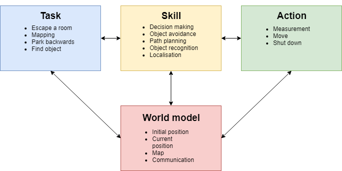 |
| Figure 1: Interface diagram |
Escape room Challenge
In the Escape room challenge PICO was placed on an arbitrary location in a rectangular room from which it had to escape through a corridor. This had to be done as fast as possible.
Wall follower
In order to complete this challenge, a so-called Wall follower algorithm was built and implemented. The steps that the algorithm makes in order to complete the challenge are as follows:
- Drive to the right until a wall is detected at the right side.
- Follow this wall by driving forward until a wall is detected.
- If the distance to the right wall becomes larger than a predefined threshold, compensate by driving sideways to the wall.
- When a corner is detected ahead, rotate 90 degrees to the left and align to the wall perpendicular to the previous wall.
- If the corridor is detected by an increase in distance measured at the wall side (defined by a certain threshold), PICO will drive another 25 cm forward and then rotate 90 degrees to the right.
- PICO will drive forward and then align to the right wall again, allowing it to exit the room.
For detection, PICO uses sensor-data of the sensors located perpendicular to its forward driving direction. These sensors are used to find the distance to walls at its left and right side, defined as LeftDistance and RightDistance respectively. The sensor that is aligned with the forward driving position is used to find the distance to a wall that is in the forward driving direction, defined as ForwardDistance. The detection of a corner as described in step 5 is done by looking at ForwardDistance and RightDistance. When both of these distances become lower than a predefined threshold, a corner must be present at the right side, and therefore, PICO should rotate to the left. By using this algorithm, PICO is able to find the corridor of the room and escape the room.
Testing
The testing sessions with PICO were used for testing the algorithm and fine tuning some parameters in the model, such as velocities, rotational velocities and required minimal distances to walls. During the testing, it was found that there is a large difference between the simulation and reality. First, it was concluded that the odometry of PICO should not be trusted too much for localization and moving around. This could be noticed at the 90 degrees rotation that was used. The actual rotation PICO made had a noticeable offset. A possible solution to this problem was using the wall at the side to determine if PICO is aligned with the wall by using additional sensor data. This solution was implemented and tested in the simulation. In the simulation, the solution worked quite well for making the corners, but it also caused some unexplainable and unwanted behaviour. Due to a lack of time, no solution to this problem could be found and therefore, this was not implemented for the Escape room challenge. Another flaw that occurred during testing was that PICO did not always detect the wall at its right side in step 1, and because of this, PICO hit the wall. This did not happen in any of the simulations, and it remains unclear why this happened during testing. Despite these two problems, PICO was able to get out of the room once during testing.
The Challenge
During the challenge, the second problem that was discussed above obstructed PICO from finding the exit. PICO failed to detect the wall at its right side and drove into it, which is shown in Figure 2 below. Unfortunately, this happened at both trials. After evaluation of the Escape room challenge, it was concluded that a different approach was required for the Hospital Challenge. This means that from this point on, the Wall follower algorithm is abandoned and a new a plan for a new approach is made.
|
| Figure 2: PICO during the escape room challenge |
Conclusion
A relatively simple algorithm was made for the Escape room challenge, which finds and then follows the wall at its right side until it detects the exit. Based on simulations, this algorithm was sufficient for completing the Escape room challenge. However, during testing, multiple differences were observed between the simulation and reality. It is learned that navigating using purely PICOs odometry is overall not a smart strategy, and therefore this strategy will no longer be used from this point. Hitting a wall due to a detection error was the reason the Escape room challenge ended premature for PICO, the exact cause of this error has not been found. This is however not an issue for the final challenge, because the next step is going back to the drawing table and come up with a new plan.
Hospital Challenge
The second and final challenge is the Hospital Challenge. In this challenge, PICO has to find an unknown object in a hospital environment which consists of a hallway and multiple rooms. After the Escape Room Challenge a new plan is made to successfully complete the Hospital Challenge. This plan consists of three phases: mapping the hospital, parking against the wall and finding the object. During these phases, PICO needs skills such as world mapping, localization, path planning and object detection. Furthermore, PICO needs to be able to move through the hospital without hitting any of the walls. How the mapping, parking and object detection are performed and how these functions are implemented is explained here.
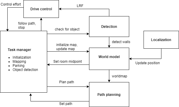 |
| Figure 3: Overview of the software architecture |
World mapping
In the first phase of the challenge, PICO has to make a map of the environment. To accomplish this, an external library called MRPT (Mobile Robot Programming Toolkit) is used. This library contains some useful classes, that help us to efficiently program the software required for PICO to accomplish its task. The first task is to process the laser range data of PICO. The class CObservation2DRangeScan is used, which takes as input a vector with range data, a binary validity vector and the aperture of the range scan. The validity vector is used to consider which data points are valid to for example filter out the outer data points which contain a significant amount of noise. The CObservation2DRangeScan object is inserted in a second class, the CSimplePointsMap. Each valid point is inserted into the map which contains the 2D coordinates of the points where the laser range finder detected a wall. The first set of data is used to create a points map for the world map. Now of course the world map needs to be updated with the new measurements. A second CSimplePointsMap object is created to store the current range data of PICO. Then an iterative closest point algorithm (Levenberg-Marquardt) , implemented in the CICP class [7], is used to fit the points of the world map and current view to each other. It takes the current position as initial guess for the fitting and tries find the optimal pose between the map of the current view and reference worldmap. From the displacement and rotation of the current view with respect to the world map, the location and rotation of PICO is obtained with respect to its starting position. This way both PICO’s position and world map are continuously updated. The map can be output as a bitmap image and can be used to recognize the location of the rooms and doors.
Path planning
For the navigation of PICO, the path planning algorithm implemented in the PlannerSimple2D class is used. It uses a wave front algorithm to find the shortest path between position and target. An example of the wave front algorithm is shown in Figure 4 below. Like in many other path planning algorithms, the wave front algorithm uses a grid map for processing. Because of this, the PlannerSimple2D class only takes a grid map in the form of a COccupancyGridMap2D object as input and therefore the points map is first converted to a grid map object. Each point from the world map is inserted in the COccupancyGridMap2d object, which based on input of the maximum x- and y-range determines which cells are occupied and which not. The grid map is inserted in the PlannerSimple2D class to compute the desired path. The path planner object also contains the value for the radius of the robot. It enlarges the walls by this radius to make sure the found path does not intersect with the walls. The path is returned as a set of points with a given step size, which can then be used for navigation.
Phase 1: Mapping the hospital
In phase 1, PICO will be building a map of the hospital by using the world mapping and path planner as described above. Once this is done, PICO will return to its starting position and park there. Next to this, PICO will use the map for defining rooms and doors in the hospital. These features are further explained here.
Initialize map
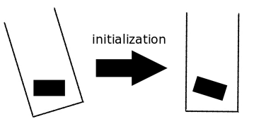
At the start, PICO will be placed at an arbitrary angle with respect to the hospital walls. In the "Initialize map" phase, PICO uses the initial view to compensate this arbitrary starting angle. In order to do this, the data from the first measurement of laser data is used to determine the angle of PICO with respect to the walls in the hallway. The initial view and initial angle are then used to initialize the world map and correct the rotation of the world map so that the walls are parallel with the x- and y-axis. In order to clarify the result of this initialization a bit more, the situation before and after the initialization is shown in Figure 5. A code snippet of the determination of the initial angle is given.
|
| Figure 5: Initialization of the worldmap |
Building the map
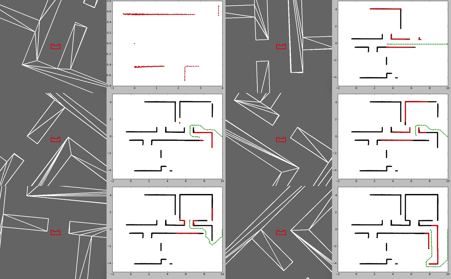
The World Mapping algorithm and the Path planning algorithm are combined in order to map the hospital. The path planning algorithm is provided with a setpoint that is located outside the hospital. The setpoint is positioned sufficiently far away guaranteeing that it will be located outside the hospital. The path planning algorithm will compute a path to the setpoint and PICO will follow this path while scanning its environment and creating the map. While following the path, the hospital will be further explored and the path will be blocked by the walls that are detected. The path planning algorithm will continuously compute a new path to the given setpoint taking the known map into account and thus finding a way around the detected walls. The path following is repeated, until no path can be found towards the setpoint. This means that the contour of the hospital is closed and all rooms have been visited. At this point, PICO will return to its starting position to initiate the parking against the wall. In Figure 6, a simulation of the mapping procedure is shown. A code snippet on how the worldmap is updated is given.
|
| Figure 6: Simulation in which PICO is building a map of a hospital |
Parking
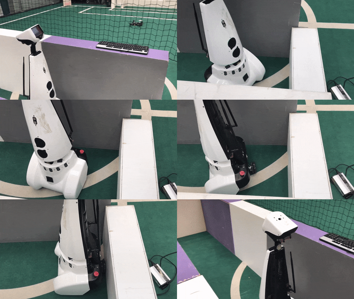
Once the map of the hospital is finished, PICO will start the parking phase. The path planner will plan a path back to the starting position based on the world map that is made. After arriving at the starting position, PICO will rotate to an angle of 180 degrees, such that it is facing the wall it will park against. The frontal distance to the wall is measured and PICO will rotate back to an angle of 0 degrees, such that it faces the wall backwards.
PICO will start driving backwards with a reduced speed, for the distance it measured, until it touches the wall. For extra robustness, PICO will make use of the control effort data, so that it stops driving backwards once it touches the wall and the control effort output reaches a certain threshold. PICO is now parked and ready to find the object! The parking phase of PICO is shown in Figure 7 below.
|
| Figure 7: PICO in the Parking phase |
Define rooms
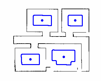
With the use of the worldmap, rooms and doors are located. To locate the rooms, first a set of image adjustments are performed on the worldmap, with the use of opencv. First the image is processed using erosion.[1] With the erosion process the walls in the image are thickened until the hallway and doors are all filled. This results in white spaces that represent a piece of the rooms, see Figure 8. In the processed image the contours are found using the opencv function findContours which is able to find contours in a binary image. [3]. The function is set to construct a full hierarchy of nested contours, i.e. of the contours the children and parent contours are known. This is necessary since the largest contour is represents the entire hospital, the parent contour, and this is not of interest. For the contours of the rooms the moments are calculated using Green’s formula [6]:
[math]\displaystyle{ m_{ji}= \sum_{x,y}(array(x,y) \cdot x^j \cdot y^i) }[/math].
With the moments the center of the room [math]\displaystyle{ (\bar x,\bar y) }[/math] is calculated as:
[math]\displaystyle{ \bar x = \frac{m_{10}}{m_{00}},\qquad \bar y=\frac{m_{01}}{m_{00}} }[/math]
In Figure 8 an example is given for the contours and center points. A code snippet is given.
|
| Figure 8: Midpoints and contours of simulation |
Locate doors
After the world map is obtained, the inside of the hospital is marked by coloring the pixels. The walls and the surroundings of the hospital are marked with a different color. To be able to do this, the inside of the hospital needs to be surrounded by a closed contour, so no gaps are allowed in the walls of the hospital. This is achieved by using a combination of the opencv functions erode and findContours.[1][3] The function erode thickens lines and pixels in any direction. This is applied until all the gaps in the walls are closed, doors and hall way remain open. Subsequently, the function findContours can now find the closed contour which surrounds the inside of the hospital. Now the inside of the hospital can be marked and it surroundings can be marked with a different colour, see Figure 9.a.
Using the opencv function cornerHarris [2] all corners of the hospital are detected. Subsequently, two types of corners are distinguished, namely corners that cover 90 degrees or 270 degrees of the inside of the hospital. Only the corners that are 270 degrees are used for further analysis, see Figure 9.b. The set of corners that are 270 degrees are sorted in vertical and/or horizontal pairs only if they are 1.5 m apart or less and either the x-coordinate (vertical pair) or the y-coordinate (horizontal pair) is (approximately) the same.
To find doors that consist of 4 corners, the vertical pairs of two are sorted in quartets only if the y-coordinates of the two pairs are aligned such that together they could form a door. Subsequently, it is checked if the whole space in between the 4 corners of each quartet is marked as the inside of the hospital. If this is the case it is also checked if at least on the right or top of the so called door the pixels are marked as wall or surrounding. The latter is done to ensure that open spaces in between two doors that in front of each other are not detected as a door as well. If both requirements are fulfilled a 4 corner door is found. In Figure 9.c can be seen that the door detection works for the possible hospital map that was provided. A similar procedure was thought of for doors consisting of 2 corners. For vertical pairs it is checked if either left or right of the pair the pixels are marked as wall or surrounding. Suppose that on the right size of the vertical pair the pixels are marked as wall or surrounding, then the width of the door is determined by finding the nearest wall to the left of this vertical pair. For horizontal pairs it is checked if either above or below of the pair the pixels are marked as wall or surrounding and the width of the door is determined by finding the nearest wall to the top or bottom of this horizontal pair.
|
|
|
| Figure 9.a: Marking the inside and outside of the hospital in simulation | Figure 9.b: Detecting 270 degrees corners in simulation | Figure 9.c: Doors in simulation |
When a door is located it is key that the pixels which are identified as the door opening are calculated. Combining this information with the center points of the rooms the hint can be used. The path planner is asked to plan a path to the center point of a room. When the path is know it can be checked through how many door openings the path goes to get to the room. When this is applied for all rooms it can be calculated for which room the most doors must be passed to get to it and the room in which the object is found.
Unfortunately, since the opencv function erode might need some manual tuning for the amount of erosion it was considered unreliable. In Figure 10.a the result of successful erosion can be seen for a world map of real (non-simulated) laser data after tuning the settings manually. Furthermore, erosion on a less perfect real-life map had as a consequence that corners of rooms get misshaped and can no longer be detected by the opencv function cornerHarris, see Figure 10.b. Therefore it was decided to not implement this part for the final challenge.
|
|
| Figure 10.a: Marking the inside and outside of the hospital of the final challenge | Figure 10.b: Detecting 270 degrees corners of the final challenge |
Phase 2: Finding the object
With phase 1 completed, PICO now has access to room and door locations. Next to this, it knows the full layout of the hospital, which means that it can navigate anywhere in the hospital using the Path planning algorithm. The final piece of information that is used in order to find the object is the hint that is provided:
The object will be located in the room for which most openings (i.e., doors) have to be passed through to enter it.
Based on all of this information, a strategy is made in order to find the object as fast as possible. This means that, based on the hint and the locations of the doors and rooms, PICO should immediately identify in which room the object is located, and identify the object once it is this room. How this is realized, is explained here.
Connection diagram
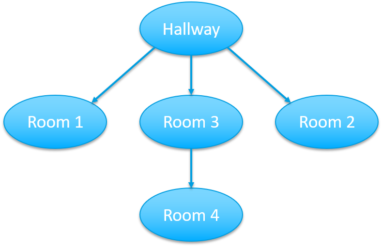
With the known locations of the rooms and doors a connection diagram can be drawn, see Figure 11. In this diagram the connections between the rooms and the hallways are drawn. For example, if one is standing in the hallway and would want to visit room 4 it has to pass through room 3 first.
|
| Figure 11: Room connection diagram |
To connect the doors to the right room, the path planning algorithm is used. For every room the shortest path from the origin is planned. An iteration over the setpoints of the path is made and it is checked if the setpoints lie in the contour of the four points of the doors, by means of the opencv’s function pointPolygonTest.[4] If a setpoint lies in the contour of a door, it means the door must be passed through in order to reach the room from the origin. The number of doors that are passed through are counted and the room that needs the most doors to be passed through is passed through to the find-object phase. It is taken into account that a door can be passed through only once in every path, i.e. if more setpoint of a single path lie in the contour of the same door, the door is only counted once.
Object detection
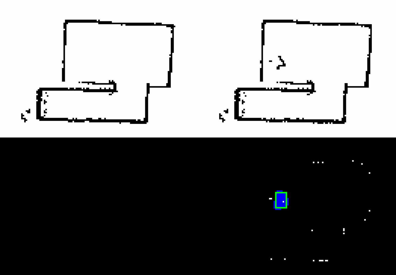
For PICO to complete the find object phase it has to stop near the object; Therefore, only using the high-level hint is not enough. While driving to the target room, PICO starts it object detection phase. In this phase PICO constantly compares the map of the hospital, made in the mapping phase, with the current updated map by subtracting the maps from each other. The result is a map where only differences are visible.
Since both the map made in the mapping phase and the current map can have noise in it, the noise must be filtered and not be confused for the object. For the difference map all the contours are computed (findContours [3]) and only the largest contour is checked, i.e. the largest difference. For the largest difference in the map the bounding rectangle is calculated using opencv’s boundingRect [5], i.e. a rectangle that fits the contour. If this rectangle has dimensions larger than a predetermined minimal height and width, the rectangle is identified as the object and the coordinates of the object are saved. If the rectangle does not suffice for the predetermined dimensions, the routine of comparing the current map with the hospital map is repeated.
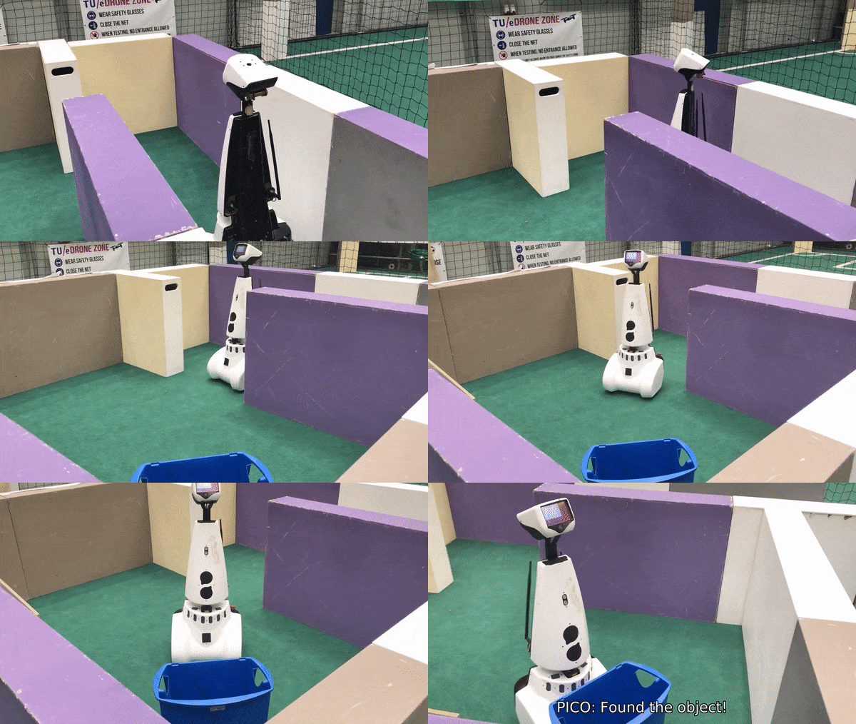
When PICO has identified the object the path planning algorithm computes a path to the object and PICO is to follow the path until it is at a minimal set distance of the object. Once it is at the object location, PICO stops driving and will speak: “I have found the object”. A video of PICO successfully finding an object and the corresponding OpenCV processing are shown below. A code snippet of the object detection is given.
| |
| Figure 12: PICO finding and driving towards the object. | |
| |
| Figure 13: Comparing two maps for differences and object detection. | |
The Challenge
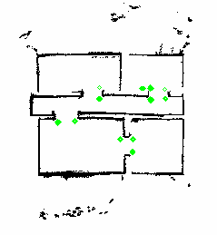
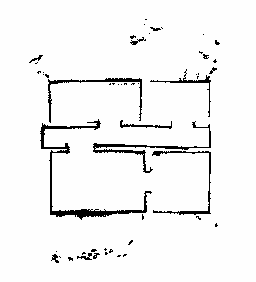
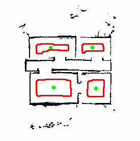
During the hospital challenge PICO was able to successfully map the hospital and park backwards. PICO moved at a slow pace but because of the path planning algorithm, used to map the hospital, PICO was able to map the hospital quickly. The map of the hospital is given in the Figure 14.a. Besides the rooms and hallway of the hospital some noise was measured outside the hospital. This is due to the readings of the LRF over the walls. With the complete map PICO was able to plan a path back to its origin and park backwards. After the hospital map was completed, the map was post processed as explained in Define rooms to find the rooms. The noise mapped outside the hospital was not off influence on the detection. The rooms that were detected are illustrated in Figure 14.b.
| |
| |
| Figure 14.a: Worldmap created during the challenge | Figure 14.b: Midpoints and contours of hospital challenge |
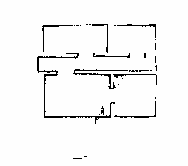
During the challenge, the door detection was not yet implemented as described in Locate doors. Therefore, the hint was not implemented. In the object detection phase PICO was set to drive towards the midpoints of the detected rooms in random order to search for the object. During the two official tries the localization of the object failed. As can be seen from the worldmap in Figure 14, there is a lot of noise at the bottom and top of the map. Because the walls on these sides were just not high enough, PICO was able to see over the walls a little and able to observe the people outside the staging area. During the mapping this was no issue, since objects outside did not interfere with the mapping process, but during the object detection phase, some people moved and this was detected as a new object. Since this was not the correct object and since it was outside the hospital and could not be reached, the challenge could not be finished. In a third unofficial try, we tried again by stacking another layer of boxes on the sides. As can be seen in Figure 15, the noise on the bottom and top are almost completely gone, which should have made a successful run possible. Unfortunately, the object detection was still not robust enough. Instead of immediately stopping because it detected an object outside the hospital, PICO was able to traverse the hospital again for a short while. The noise on the outside was not visible anymore, so the extra layer of boxes definitely helped, but unfortunately a wrong object was identified again. This was likely just some noise on the walls of the hospital, which created an extra layer of pixels on the walls in the gridmap. This resulted in the extra line of pixels in the difference between the maps being misidentified as the object. Although the object detection worked during testing, it was not robust enough to fulfill its task every time.
|
| Figure 15: Worldmap created during a third unofficial try after the challenge. As can be seen, the noise on the bottom and top is gone because of the extra layer of boxes. |
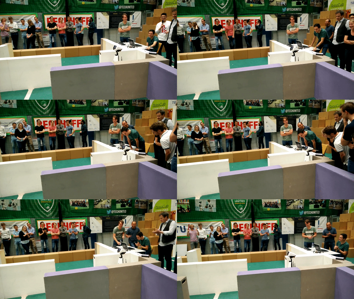
A video of PICO in action during the mapping in the Hospital Challenge is uploaded to YouTube and can be found by clicking here. The parking phase during the Hospital Challenge is shown in Figure 16 below.
|
| Figure 16: Parking during the Hospital Challenge |
In order to show both the mapping and the parking phase in one trial, the video of an unofficial (3rd) trial that was performed is used. This video can be found by clicking here.
One improvement on PICO should be the drive control while following the path. PICO is driving very slowly, which could be improved by tuning the drive control algorithm further. Another improvement should be the manner of how PICO follows the path. Currently, PICO first rotates towards the next setpoint and then drives forward to it. Since the setpoints lie close to each other, it should be possible for PICO to drive towards the setpoint immediately, by means of simultaneous X and Y translation. Last, an improvement should be the robustness of the object detection. As seen in Figure 15 not all the walls are completed during the mapping phase, which has no influence on the door and room detection. While detection objects, most of the straight lines are filtered to identify difference between the object and not yet fully discovered walls. However, small changes in worldmap, like initially or further wrong readings, smaller part of walls and the detection outside of the hospital could cause PICO to identify the object falsely.
Conclusion
The solution that is found for the Hospital Challenge is a relatively simple, yet very effective solution. We make use of some external libraries that make the implementation easier and use these in a smart way in order to achieve the goal of this challenge. By making using of a SLAM implementation we are able to map the hospital and localize where PICO is with respect to its starting position. By using a path planner navigation throughout the hospital is optimized and it is ensured that PICO will stay away from the wall, without having to implement complicated detection/force-field algorithms. This solution resulted in the fact that PICO was able to complete most of the challenge. The resulting map of the hospital looks very good (without the outside noise) and navigation and parking went flawless. PICO was able to successfully complete the map and drive back to the origin where it parked. After parking, PICO correctly identified the rooms from the world map and set its waypoint to find the object, but failed by misidentifying the object. With a little more time we could have made the object detection slightly more robust and PICO would have likely been able to complete the full challenge.
Finally, although we did not complete the full challenge we are still proud that our group came furthest and that we won the first prize!
Part of code
Some code snippets of the more interesting parts of the code are given below.
References
[1] Eroding and Dilating (2017). In OpenCV 2.4.13.4 documentation. Consulted on May 22, 2018. https://docs.opencv.org/2.4.13.4/doc/tutorials/imgproc/erosion_dilatation/erosion_dilatation.html
[2] Harris corner detector (2018). In OpenCV 2.4.13.6 documentation. Consulted on May 28, 2018. https://docs.opencv.org/2.4/doc/tutorials/features2d/trackingmotion/harris_detector/harris_detector.html
[3] Finding contours in your image (2017). In OpenCV 2.4.13.4 documentation. Consulted on May 31, 2018. https://docs.opencv.org/2.4.13.4/doc/tutorials/imgproc/shapedescriptors/find_contours/find_contours.html
[4] Point Polygon Test (2018). In OpenCV 2.4.13.6 documentation. Consulted on June 5, 2018. https://docs.opencv.org/2.4/doc/tutorials/imgproc/shapedescriptors/point_polygon_test/point_polygon_test.html
[5] Creating Bounding boxes and circles for contours (2018). In OpenCV 2.4.13.6 documentation. Consulted on June 4, 2018. https://docs.opencv.org/2.4/doc/tutorials/imgproc/shapedescriptors/bounding_rects_circles/bounding_rects_circles.html
[6] Structural analysis and Shape Descriptors. In OpenCV 2.4 documentation. Consulted on June 9, 2018. https://docs.opencv.org/2.4/modules/imgproc/doc/structural_analysis_and_shape_descriptors.html?highlight=moments#moments
[7] SLAM ICP Simple Example. From MRPT sample. Consulted on June 19, 2018. https://github.com/MRPT/mrpt/blob/master/samples/slam_icp_simple_example/test.cpp
