Smart Mobility and Sensor Fusion: Difference between revisions
| (2 intermediate revisions by the same user not shown) | |||
| Line 70: | Line 70: | ||
For the case of the mobility scooter, small environments will require the most detailed sensory information in order to navigate seemlessly. For this purpose, we take a look at the research conducted in 2017, by Varuna de Silva, Jamie Roche and Ahmet Kondoz <sup>3</sup>. In their research, a quad-bike was equipped with both a camera and a LiDAR system, and an office floor was used as a test environment. Considering such a test environment closely resembles many of the environments the mobility scooter will navigate through, a more detailed summary of the research paper will be presented.<br> | For the case of the mobility scooter, small environments will require the most detailed sensory information in order to navigate seemlessly. For this purpose, we take a look at the research conducted in 2017, by Varuna de Silva, Jamie Roche and Ahmet Kondoz <sup>3</sup>. In their research, a quad-bike was equipped with both a camera and a LiDAR system, and an office floor was used as a test environment. Considering such a test environment closely resembles many of the environments the mobility scooter will navigate through, a more detailed summary of the research paper will be presented.<br> | ||
<b>Important</b>: All images used in the "Fusion process", "Proposed Algorithm" and "Hardware and Results" sections belong to the research of Varuna de Silva and his colleagues. They have granted permission to show their research as an example. | |||
<b>Important</b>: All images used in the "Fusion process", "Proposed Algorithm" and "Hardware and Results" sections belong to the research of Varuna de Silva and his colleagues. They have granted permission to show their research as an example.<br> | |||
The start of the investigation gives an example for the images that need to be fused in the process. The images can be seen below: <br> | The start of the investigation gives an example for the images that need to be fused in the process. The images can be seen below: <br> | ||
[[File:paperimage001.jpg|300px]] | [[File:paperimage001.jpg|300px]] | ||
[[File:paperimage002.jpg|220px]] | [[File:paperimage002.jpg|220px]] | ||
<br><br> | <br> | ||
<i>images belonging to the research</i> <sup>3</sup>.<br> | |||
The paper presents a new way to fuse data from the LiDAR sensor (a 3D point cloud) with the luminance data from a camera image. The image taken by the camera provides a high-resolution 2D view from (part of) the direct environment. However, it is not sophisticated in sensing depth. LiDAR scanners, on the other hand, provide high accuracy in measuring image-depth, albeit delivering a lower resolution than the camera. See below for the sensor-setup used in the research. <br> | The paper presents a new way to fuse data from the LiDAR sensor (a 3D point cloud) with the luminance data from a camera image. The image taken by the camera provides a high-resolution 2D view from (part of) the direct environment. However, it is not sophisticated in sensing depth. LiDAR scanners, on the other hand, provide high accuracy in measuring image-depth, albeit delivering a lower resolution than the camera. See below for the sensor-setup used in the research. <br> | ||
| Line 82: | Line 84: | ||
[[File:paperimage004.jpg|400px]] | [[File:paperimage004.jpg|400px]] | ||
<br> | <br> | ||
<i>images belonging to the research</i> <sup>3</sup>.<br> | |||
===Proposed Algorithm=== | ===Proposed Algorithm=== | ||
| Line 94: | Line 97: | ||
<li><math>tan \gamma _C = \frac{d_l \times cos \beta \times sin \gamma _L + \Delta y}{d_l \times cos \beta \times cos \gamma _L - \Delta x}</math></li> | <li><math>tan \gamma _C = \frac{d_l \times cos \beta \times sin \gamma _L + \Delta y}{d_l \times cos \beta \times cos \gamma _L - \Delta x}</math></li> | ||
</ul> | </ul> | ||
<i>functions belonging to the research</i> <sup>3</sup>.<br> | |||
For these equations to be applied for geometrically aligning the sensor outputs from the camera and LiDAR scanner, calibration of the hardware must provide the values for <math>H_C</math> , <math>H_L</math> , <math>\Delta y</math> and <math>\Delta x</math>.<br> | For these equations to be applied for geometrically aligning the sensor outputs from the camera and LiDAR scanner, calibration of the hardware must provide the values for <math>H_C</math> , <math>H_L</math> , <math>\Delta y</math> and <math>\Delta x</math>.<br> | ||
| Line 112: | Line 116: | ||
[[File: paperimage006.jpg|800px]] | [[File: paperimage006.jpg|800px]] | ||
<i>images belonging to the research</i> <sup>3</sup>.<br> | |||
---- | ---- | ||
Latest revision as of 19:28, 22 March 2018
To go back to the mainpage: PRE2017 3 Groep6.
Explaining feedback requirements
To start off with, the mobility scooter should contain a (touchscreen-)display on which users can view data that is relevant to them and their current location/situation. For example, the estimated time of arrival can be displayed alongside a weather notification to ensure the user does not accidentally travel through a rainstorm.
Other items to display are of course the battery status, tire pressure, current velocity, available range with the current battery charge, connectivity information such as contacts and (video)calls and means of entertainment such as music and videos.
The purpose of the display and speakers is not only to entertain the user and provide useful information. It could also be seen as a more subtle attempt at keeping the user occupied in order to prevent them taking over the wheel without proper cause. Of course, this is at the same time a disadvantage considering the user will be less aware of their environment when viewing the screen.
Aside from the screen, there is also need for auditory feedback. Not only for the user of the mobility scooter, but also for their direct environment (such as pedestrians). In case of a sudden stop, the user will prefer to be informed of the reason. In case a pedestrian is not paying attention to the road (using their phone, for example) they should also receive a warning sound from the mobility scooter, preventing them from walking into it.
Considering there can be many physical reasons for a person to be in need of an autonomous mobility scooter, taking over control in case of an emergency should be possible through different approaches. Some users may want to use a joystick, while other can prefer voice controlled operation or even no further movement at all, meaning a physical kill-switch is a necessity.
Connecting to devices like smartphones or smartwatches can be seen as a luxury more than a necessity, but these can actually be helpful in using the scooter. For example, the user can check their scooter's battery status before even leaving their couch, as well as entering their destination beforehand. This can be used for many functionalities.
In case of an (medical) emergency, it would be highly beneficial for the scooter to send out an emergency distress signal to both the authorities and close family members or friends of the victim.
Communication between different mobility scooters can be applied to increase the efficiency of the navigation system, as well as improving the accuracy of several measurement systems, such as a local weather estimate and maybe even a sensor checking whether certain roads are slippery during the winter. A mobility scooter that is currently located in a supermarket which is swamped with customers, can "warn" other scooters throughout the network to alter their current plan. Their respective users can then receive a notification asking them whether they want to continue to the supermarket or maybe start with the postal office instead.
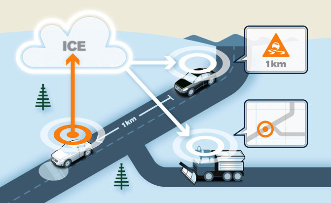 This is an example displaying the use of machine-to-machine communication, in the way of warning others for a slippery road.
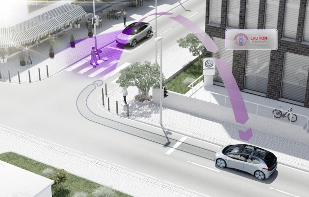 This example refers to scooters giving others a headsup of the amount of pedestrians in certain locations.
As soon as this system works, as it already does amongs several car brands, it can be extended in the way that scooters can also start communicating with cars and other vehicles instead of solely with other scooters. Imagine a car needs to turn back because of a road being (suddenly) closed, this can be communicated to scooters as well, to save the users time and battery usage, improving their travel efficiency and reducing the chance they run out of juice.
https://www.technologyreview.com/s/534981/car-to-car-communication/ (explaining how car to car communication already works, this can be extended to mobility scooters)
Multi-Sensor Data Fusion
This chapter is currently under research and is susceptible to major changes
In order for the autonomous mobility scooter to be "aware" of its own surroundings, several different types of sensors will be included in the final model. However, every sensor has its own way to process sensory information through hardware as well as software. Considering all data needs to be taken into account at the same time, there is need for some way to combine the different sensor outputs. The technique that is required in this case is that of Sensor Fusion. The idea here, is to create a method to combine various outputs from different types of sensors, or simply to combine several outputs of the same sensor created over a longer period of time.
An example of the application of Sensor Fusion in the autonomous mobility scooter would be to scan the distance from the scooter to objects around it repeatedly in short intervals. By doing so with all attached proximity sensors, the scooter can be aware of potential collisions before they occur, and also adjust its speed to pedestrians walking behind or in front of it.
The idea would be that this combined data package from all proximity sensors can also be combined with information provided by other hardware, such as Radar/LIDAR and camera(s).
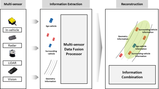
For a visual explanation, see the image below. This is an example created for autonomous cars, which can be extended to the application in autonomous mobility scooters as well. The image provides a simple display of how the car's various sensors can provide a more detailed image of direct environment surrounding the vehicle.1
Aside from providing sensory information for the surroundings of the scooter, making use of a variety of sensors also improves the quality of the data. For example, a camera provides more detailed images than a radar in terms of color and resolution, but it is highly susceptible to weather circumstances. Using a combination of both delivers the best result. This reasoning extends to other sensors as well, such as proximity sensors.
Also, using sensor fusion to combine sensory data lowers the chance of data being inaccurate. A single sensor can malfunction for various reasons (by simply breaking down, or magnetic interference for example). Combining and comparing data from other sensors can reveal certain errors in hardware before negative consequences occur.
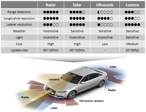
Below is an image displaying the different kinds of sensor strengths and weaknesses for Radar, Lidar, Ultrasonic sensors and cameras.1 This is so far merely an example which could be put to use when necessary.
The Kalman Filter
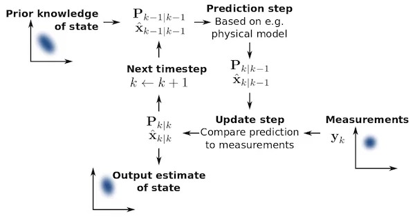
The Kalman Filter can be attended to in case of broken sensory hardware. The idea of the Kalman Filter is quite simple, in that it means to (temporarily) fix or ignore data received from broken or inaccurate sensors. The Kalman Filter first checks the prior knowledge for any sensor, after which it creates a prediction for the next piece of data alongside the actual measurement. In case the actual measurement does not make sense in the case of that specific sensor and prior knowledge, the Kalman Filter chooses to reduce the amount of influence that sensor provides to the entire system, so that sensors that are not malfunctioning can take over for that iteration.
An other, more simplistic method to cope with malfunctioning sensors, would be to take the average of all incoming sensory data. However, the way the Kalman Filter method works ensures that the entire system can theoretically still operate when a majority of sensors is malfuntioning. (It only allows sensors to participate in the sensor fusion model when they are behaving properly). A visual representation for the Kalman Filter method is shown below.2
Of course, combining a variety of sensors drastically rises the costs for the mobility scooter. One needs to find an optimal amount and variety to achieve the most cost-efficient outcome for this specific goal.
Sensor Choices
For the autonomous mobility scooter to function properly in all applicable enviroments, it is wise to consider the combination of different sensors that is also used for other autonomous vehicles such as cars. These have been thoroughly tested and proven to work. In this case we are talking about using a camera, radar, LiDAR (Light Detection and Ranging) and ultrasonic (proximity) sensors. Among these four different sensors, the radar is the first to be omitted in case of high costs or other restrains such as available mounting space. This because the radar in cars is used for long-range aspects, which will be less relevant on a mobility scooter with its lower velocity.
With regards to the time that is available for this research, the application of sensor fusion will be focusing on fusing the sensor outputs of a LiDAR scanner and a wide-angle camera. This could later be extended to the proximity sensors and, if applicable, the radar.
A camera can provide a high resolution image of the scooter's surroundings which the LiDAR can then improve by adding a more detailed 3D mapping to the images.
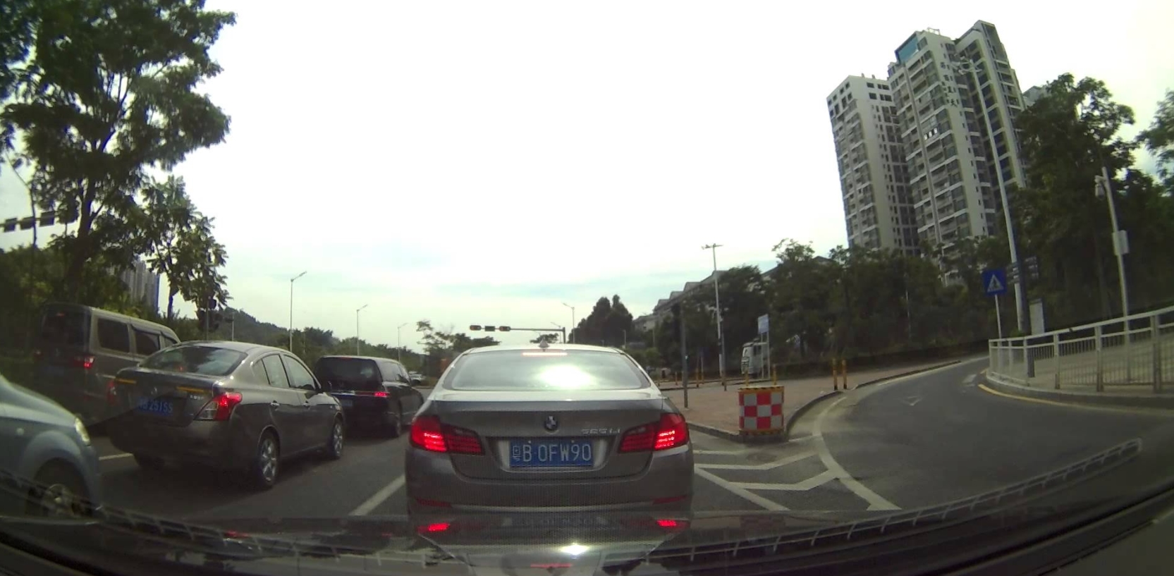
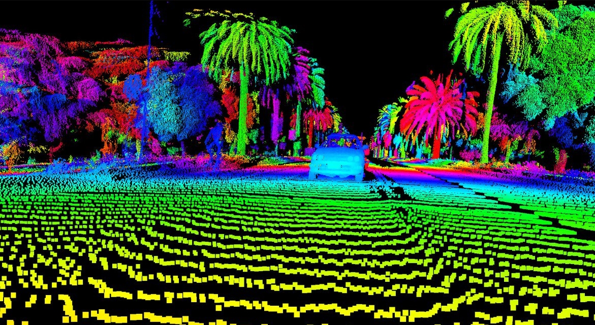
Two (different) examples to show an image from a wide-angle camera next to that of a LiDAR system.
The outputs of both the LiDAR and camera have different spatial resolutions and need to be aligned in order for the scooter to use them in its movement decisions. The first step is to align the images in terms spatial environmental data, after which it might be useful to interpolate missing data in the resulting image combination.
Fusion process
For the case of the mobility scooter, small environments will require the most detailed sensory information in order to navigate seemlessly. For this purpose, we take a look at the research conducted in 2017, by Varuna de Silva, Jamie Roche and Ahmet Kondoz 3. In their research, a quad-bike was equipped with both a camera and a LiDAR system, and an office floor was used as a test environment. Considering such a test environment closely resembles many of the environments the mobility scooter will navigate through, a more detailed summary of the research paper will be presented.
Important: All images used in the "Fusion process", "Proposed Algorithm" and "Hardware and Results" sections belong to the research of Varuna de Silva and his colleagues. They have granted permission to show their research as an example.
The start of the investigation gives an example for the images that need to be fused in the process. The images can be seen below:
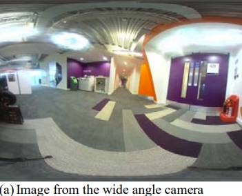
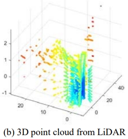
images belonging to the research 3.
The paper presents a new way to fuse data from the LiDAR sensor (a 3D point cloud) with the luminance data from a camera image. The image taken by the camera provides a high-resolution 2D view from (part of) the direct environment. However, it is not sophisticated in sensing depth. LiDAR scanners, on the other hand, provide high accuracy in measuring image-depth, albeit delivering a lower resolution than the camera. See below for the sensor-setup used in the research.
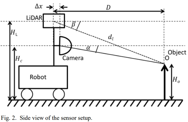
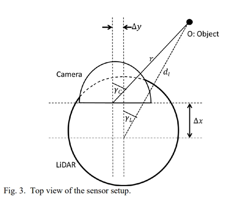
images belonging to the research 3.
Proposed Algorithm
As a first step in the data fusion process, the authors aim to geometrically align the data points for the camera and LiDAR outputs. This means that they want to link the correct pixel in the camera image to the matching data point in the LiDAR scan. Using the data from the images above and the following functions consequtively, we get:
- [math]\displaystyle{ D = d_l cos \beta \times cos \gamma _L = r \times cos \alpha \times cos \gamma _C + \Delta x }[/math]
- [math]\displaystyle{ H_O = H_L - d_L \times sin \beta = H_C - r \times sin \alpha }[/math]
- [math]\displaystyle{ tan \alpha = \frac{((H_C - H_L) + d_L \times sin \beta ) \times cos \gamma _C}{d_l \times cos \beta \times cos \gamma _L - \Delta x} }[/math]
- [math]\displaystyle{ d_l cos \beta \times sin \gamma _L = r \times cos \alpha \times sin \gamma _C + \Delta y }[/math]
- [math]\displaystyle{ tan \gamma _C = \frac{d_l \times cos \beta \times sin \gamma _L + \Delta y}{d_l \times cos \beta \times cos \gamma _L - \Delta x} }[/math]
functions belonging to the research 3.
For these equations to be applied for geometrically aligning the sensor outputs from the camera and LiDAR scanner, calibration of the hardware must provide the values for [math]\displaystyle{ H_C }[/math] , [math]\displaystyle{ H_L }[/math] , [math]\displaystyle{ \Delta y }[/math] and [math]\displaystyle{ \Delta x }[/math].
Even though the needs for calibration are small (simple spatial measurements), the geometric alignment equations will not be precise in case of (severe) calibration errors.
The next step in the algorithm for fusing the sensory outputs, is to match the resolutions of the camera image and LiDAR scan. The method used for this is based on Gaussian process regression. This is required because the camera image is of a much higher resolution than that of the LiDAR. The idea is to properly estimate the distance value for image-pixels that do not yet have a corresponding distance value from the LiDAR data. Also, doing this can reduce errors created in the geometric alignment process.
image-pixels that have a distance measurement connected to them will serve as the training set for the pixels that do not have a depth-value, during this non-linear regression technique. Also, by making use of the grey-level of pixels of the same color-group, the distance value can be further estimated.
Hardware and results
In this test, a front facing wide angle camera was used alongside a rear facing camera, combined with a LiDAR scanner of the type Velodyne VLP-16. This is a more compact LiDAR that has a low power consumption, while having a maximum operating range of 100 meters. This makes it a useful piece of hardware for the autonomous mobility scooter. In power usage, size and functioning.
In calculating the amount of free space in the direct environment of the device, only flat pieces of floor should be included. As soon as there is an object obstructing some part the of the ground, it should not be seen as free space. Also, walls should not appear as free space, even when they are the same color as the floor.
By using the fusion of the two separate images, the resolution matching process and the calculations surrounding the different grey-levels of (groups of) pixels, the available free space can be returned by the computer.
See below for visual representation of aligning the camera and LiDAR data, matching the resolution and depth-estimation for all pixels, and the (desired) resulting available free space.
images belonging to the research 3.
1 : http://vdclab.kaist.ac.kr/bbs/board.php?bo_table=sub1_2&wr_id=23&page=0&sca=&sfl=&stx=&sst=&sod=&spt=0&page=0
2 : https://www.allaboutcircuits.com/technical-articles/how-sensor-fusion-works/
3 : https://arxiv.org/ftp/arxiv/papers/1710/1710.06230.pdf
4 : http://www.i6.in.tum.de/Main/Publications/Zhang2014b.pdf
