Embedded Motion Control 2017 Group 5: Difference between revisions
| (247 intermediate revisions by 6 users not shown) | |||
| Line 1: | Line 1: | ||
[[File:SystemContext.jpg| | [[File:SystemContext.jpg|400px|thumb|right|Figure 1: System Context.]] | ||
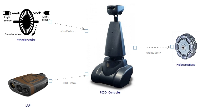
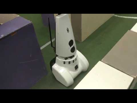
This page | This page describes the development of the PICO maze controller for the course 4SC020 Embedded Motion Control. The objective of the project is to design a controller for PICO, a mobile robot equipped with a holonomic base, wheel encoders and a laser range finder (LRF). This controller shall enable PICO to autonomously navigate through a random maze without bumping into walls. The designed system receives data from the wheel encoders and the LRF which is then used to decide what movement commands will be requested to the holonomic base. In Figure 1, an overview of the context of the system is shown. | ||
== Members Group 5 == | == Members Group 5 == | ||
<table border="1" cellpadding="5" cellspacing="0" style="width: | <table border="1" cellpadding="5" cellspacing="0" style="width:40%;border-collapse:collapse;"> | ||
<tr style="background: #D3D3D3;"> | <tr style="background: #D3D3D3;"> | ||
<td width=" | <td width="100px"><b>Name</b></td> | ||
<td width=" | <td width="80px"><b>Student ID</b></td> | ||
<td width=" | <td width="80px"><b>Email</b></td> | ||
</tr> | </tr> | ||
| Line 53: | Line 53: | ||
== Requirements & Specifications== | == Requirements & Specifications== | ||
The requirements for the system are deducted from the [http://cstwiki.wtb.tue.nl/index.php?title=Embedded_Motion_Control course page] and established from a brainstorm session. The FURPS model is used to group the requirements together in the following aspects: | The requirements for the system are deducted from the '''[http://cstwiki.wtb.tue.nl/index.php?title=Embedded_Motion_Control course page]''' and established from a brainstorm session. The '''FURPS''' model is used to group the requirements together in the following aspects: | ||
* | *'''F'''unctionality | ||
* | *'''U'''sability | ||
* | *'''R'''eliability | ||
* | *'''P'''erformance | ||
* | *'''S'''upportability | ||
A complete list of all requirements can be found in the '''[http://cstwiki.wtb.tue.nl/index.php?title=Requirements_overview requirements and specification overview]'''. | A complete list of all requirements can be found in the '''[http://cstwiki.wtb.tue.nl/index.php?title=Requirements_overview requirements and specification overview]'''. | ||
= Design = | |||
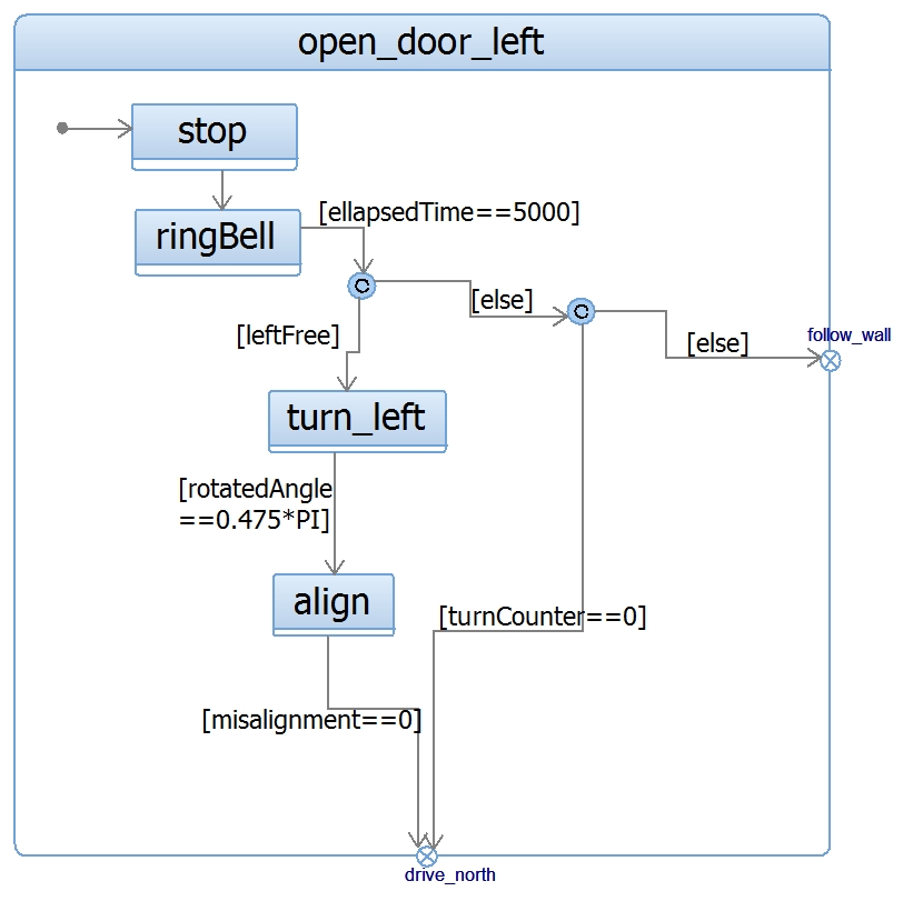
This chapter describes the design of the PICO controller. It revolves mainly around the final design implementations, but also elaborates on several functions that have remained unused and states evaluations and thoughts about the development of certain features. | |||
== Initial Design == | |||
The Initial Design document can be found here: '''[[Media:4sc020 initial design group5.pdf|Initial_Design_Group5]]'''. | |||
== Maze-solving Algorithms == | |||
Three maze solving algorithms are considered. These are elaborated in the upcoming sections, followed by a comparison and elaborate selection. | |||
'''Wall follower'''<br /> | |||
This algorithm is very simple to implement since only one rule applies: Follow the wall on either your left or right side (depending on the setting). This wall will be tracked until eventually, an exit is found. The algorithm is guaranteed to work when the robot starts at the entrance of a maze. However, if PICO starts at an arbitrary position it might get stuck in a loop, keeping track of the walls of an ‘island’. Since the case description states that the robot will be start from an arbitrary position and that the maze will contain a loop, this algorithm is risky to use and might not be able to guide the robot to the exit. | |||
'''Pledge algorithm'''<br /> | |||
The Pledge algorithm is very similar to the wall follower, but contains an upgrade to enable the robot to break free from isolated islands. The robot is given a preference direction (north, south, east or west) and follows this heading until it bumps into a wall. Then, an arbitrary (left or right) wall follower starts and keeps track of the orientation of the robot. This wall follower stops when the robot is heading towards the preference direction again and the orientation is zero degrees. Note that for this case, zero degrees is not equal to 360 degrees. Special care has to be taken when the maze is not made up of straight-angled corners, which is luckily not the case in this specific application. The Pledge algorithm is still fairly simple and guaranteed to find the exit of the maze. | |||
'''Trémaux algorithm'''<br /> | |||
The Trémaux algorithm is a more efficient, but also more complex algorithm. This algorithm keeps track of where PICO has already been by marking paths between junctions. When a junction is detected, a decision is made based on the markings that are already present on the other paths of the junction. The increased efficiency of the algorithm imposes more dependency on the detection of maze elements and maintenance of a world map. | |||
'''Selection'''<br/> | |||
It is concluded that the wall following algorithm is not a feasible option, since there is a significant chance that PICO will become stuck in a loop. In this case the robot will never exit the maze, regardless of how robust and fast the controller is. The simplest algorithm that gives a guarantee to solve the maze (of the considered) is the Pledge algorithm. Therefore, it is decided to implement this one in the controller. If there is still time before the maze challenge and if the Pledge algorithm has reached its peak performance, the transition to a Trémaux algorithm will be considered. This algorithm is theoretically capable of solving the maze more quickly but requires a more elaborate world model, which imposes significant additional work load. | |||
== System Architecture == | == System Architecture == | ||
| Line 69: | Line 95: | ||
The beginning of the development of the complex system that is the PICO controller starts by considering it as a black box: Something goes in and something else comes out. The system will gather information from the wheel encoders and the Laser Range Finder (LRF) and send actuation commands to the holonomic base accordingly. A system context diagram depicting this flow of information is shown below:--> | The beginning of the development of the complex system that is the PICO controller starts by considering it as a black box: Something goes in and something else comes out. The system will gather information from the wheel encoders and the Laser Range Finder (LRF) and send actuation commands to the holonomic base accordingly. A system context diagram depicting this flow of information is shown below:--> | ||
[[File:Functionality.jpg|800px|thumb|right|Functionality hierarchy]] | [[File:Functionality.jpg|800px|thumb|right|Figure 2: Functionality hierarchy.]] | ||
===Functionality=== | ===Functionality=== | ||
From the requirements list several functionalities can be extracted, which are arranged using the Task-Skill-Motion hierarchy. In this hierarchy one main task, the most abstract and all-embracing functionality, is specified. In this case the main task is to exit the maze. To perform this task a combination of several subordinate functionalities, the skills, is necessary. Finally, the motions are one level deeper than the skills and contain basic functionalities. | From the requirements list several functionalities can be extracted, which are arranged using the Task-Skill-Motion hierarchy in Figure 2. In this hierarchy one main task, the most abstract and all-embracing functionality, is specified. In this case the main task is to exit the maze. To perform this task a combination of several subordinate functionalities, the skills, is necessary. Finally, the motions are one level deeper than the skills and contain basic functionalities. | ||
'''Task''' | '''Task''' | ||
| Line 85: | Line 111: | ||
'''Motions''' | '''Motions''' | ||
* Process sensor data | * Process sensor data | ||
* | * Open door | ||
* | * Align | ||
* Turn base | * Turn base | ||
* Drive forward | * Drive forward | ||
| Line 93: | Line 119: | ||
[[File:Architecture.jpg|200px|thumb|right|System architecture]] | [[File:Architecture.jpg|200px|thumb|right|Figure 3: System architecture.]] | ||
===Subsystems=== | ===Subsystems=== | ||
The previously introduced functionalities are grouped together to create the subsystems | The previously introduced functionalities are grouped together to create the subsystems WorldSkills, ActionManager and MovementController. Every subsystem will be responsible for executing any of these functionalities. Figure 3 shows that the main system is composed of these three subsystems and the functionalities they are mapped to: | ||
[[File:IBD.jpg|200px|thumb|right|Internal subsystem interactions]] | [[File:IBD.jpg|200px|thumb|right|Figure 4: Internal subsystem interactions.]] | ||
===Internal flows=== | ===Internal flows=== | ||
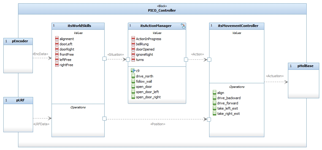
Finally, the information flows between the subsystems are specified. The incoming sensor data is gathered in the WorldSkills module, where it is converted to relevant information about the current situation and position of the robot. The situational information is then sent to the ActionManager, which will decide the upcoming action based on the situation (straight corridor / corner / T-junction etc.). The MovementController will then receive this command from the ActionManager and perform the manoeuvre using raw and processed position data provided by the WorldSkills. The diagram in Figure 4 shows this flow of data through the system. | |||
This diagram also shows various attributes and operations. These are elaborated in the subsystems' respective sections below. | |||
== | == World Skills == | ||
[[File:FilteringEMC2017G5.png|400px|thumb|right|Figure 5: Filtering of raw laser data.]] | |||
===Filtering=== | ===Filtering=== | ||
To be able to process the laser data for detecting gaps, aligning or detecting doors, it is filtered first. Consecutive points have to be within a certain distance from each other, otherwise the points will be ignored. Furthermore, this filtering is used to look at a certain bundle of beams between two specified angles as shown in Figure | To be able to process the laser data for detecting gaps, aligning or detecting doors, it is filtered first. Consecutive points have to be within a certain distance from each other, otherwise the points will be ignored. Furthermore, this filtering is used to look at a certain bundle of beams between two specified angles as shown in Figure 5. Also the maximum length of a beam can be specified. When a point is within these boundaries it is considered as a valid point. This valid point is than stored as a coordinate as shown in the lines of code below. | ||
< | <code>Struct coordinate{ | ||
:x double; | |||
:y double; | |||
::orig_r double; | |||
::orig_angle double; | |||
:} | |||
}</code> | |||
</ | |||
===Alignment=== | |||
[[File:alignment_EMC2017G5.png|400px|thumb|right|Figure 6: Alignment principle of PICO with respect to a wall.]] | |||
[[File: | |||
Guiding PICO to the exit of a maze needs a proper alignment according to the walls. Since the obtained odometry data are not as precise as in the simulations, the robot is aligned after each 90 degrees turn that is made. Important to mention is that the first thing that PICO does when the controller software is started is aligning itself. This is done because the exact position and orientation of the robot in the maze is not known beforehand. | Guiding PICO to the exit of a maze needs a proper alignment according to the walls. Since the obtained odometry data are not as precise as in the simulations, the robot is aligned after each 90 degrees turn that is made. Important to mention is that the first thing that PICO does when the controller software is started is aligning itself. This is done because the exact position and orientation of the robot in the maze is not known beforehand. | ||
For determining the alignment with respect to walls of the maze, the laser beams of both the left- and right side of PICO are used. The ranges that are used for both sides are from 80 to 100 degrees on the left and from -80 to -100 degrees on the right with 2 meters the maximum length of the beams, as shown in Figure | For determining the alignment with respect to walls of the maze, the laser beams of both the left- and right side of PICO are used. The ranges that are used for both sides are from 80 to 100 degrees on the left and from -80 to -100 degrees on the right with 2 meters the maximum length of the beams, as shown in Figure 5. | ||
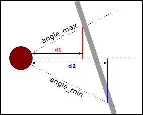
Using the Pythagorean theorem, the corresponding distance ‘d’ is calculated for each of the laser beams in the range, using its angle and length. When these distances are determined, the averages of the parts 80-90 and 90-100 degrees are determined and divided by another to determine the ratio of misalignment. If PICO is aligned to a wall this ratio is equal to -1. The turning direction can be determined by the ratio is larger or smaller than -1. The amount of misalignment determines also the turning speed, when there is a larger misalignment pico will turn faster. As clarification, Figure 6 is added in which the example as explained before is pictured. Note that in this figure only the outer beams of the range are displayed for illustration. | |||
It can be the case that the robot is in an open space and only notices a wall on one side of the robot. Since PICO is able to align using only one wall, this is not a problem at all. In this case, the range of laser beams on the side where no wall is detected is neglected. The part of the designed controller that is responsible for the alignment of PICO can be found [https://gitlab.com/emc2017/group5/snippets/1665376 here]. | It can be the case that the robot is in an open space and only notices a wall on one side of the robot. Since PICO is able to align using only one wall, this is not a problem at all. In this case, the range of laser beams on the side where no wall is detected is neglected. The part of the designed controller that is responsible for the alignment of PICO can be found '''[https://gitlab.com/emc2017/group5/snippets/1665376 here]'''. | ||
The amount of alignment that is needed for driving through the maze safely, without bumping, is set to a fixed value that is tuned during the testing sessions. Below in Figure | The amount of alignment that is needed for driving through the maze safely, without bumping, is set to a fixed value that is tuned during the testing sessions. Below in Figure 7 it is shown how PICO aligns between two walls of the maze. | ||
[[File:Align.gif|100px|frame|center|Figure | [[File:Align.gif|100px|frame|center|Figure 7: Alignment of PICO inside a maze.]] | ||
=== Side Free === | === Side Free === | ||
One of the basic skills that is implemented in the code of the robot controller is detecting if a side is free or not. When a side is free, the algorithm as used in the action manager decides if PICO drives into the free direction or continues its path. For determining if the front of PICO is free, the beams within the range of -5 to 5 degrees are free. For the detection if one or both of the sides of PICO are free, the laser ranges from 110 to 120 degrees on the left and from -110 to -120 degrees on the right or the robot are used, as indicated in Figure | One of the basic skills that is implemented in the code of the robot controller is detecting if a side is free or not. When a side is free, the algorithm as used in the action manager decides if PICO drives into the free direction or continues its path. For determining if the front of PICO is free, the beams within the range of -5 to 5 degrees are free. For the detection if one or both of the sides of PICO are free, the laser ranges from 110 to 120 degrees on the left and from -110 to -120 degrees on the right or the robot are used, as indicated in Figure 5. For the detection of the free sides of the robot, a range of 0.9 meters is used. Laser beams with an angle or length outside the specified ranges will not be taken into account by PICO. | ||
===Door detection=== | ===Door detection=== | ||
[[File:EMC2017_doors.png|250px|thumb|right|Figure 8: Possible doors in the to be solved maze.]] | |||
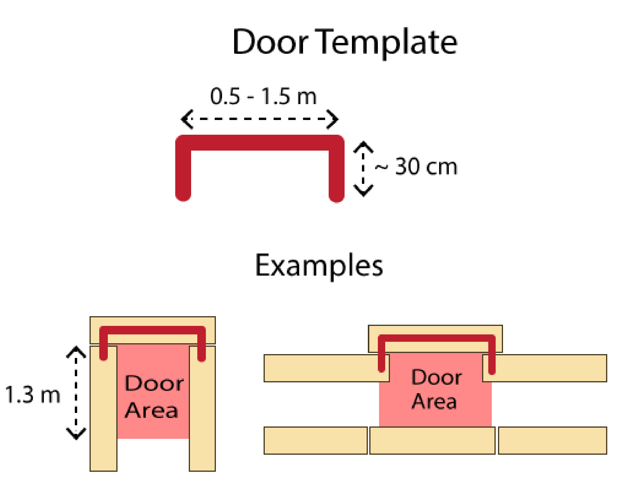
Essential for finding the exit of the maze, a door located in a dead end of a corridor or in a wall has to be opened. In Figure 8, a graphical representation of both these situations is shown. When PICO has detected a dead end, a bell will be rung and the door in the maze will be opened within a time of five seconds. Worth mentioning is that when PICO has opened a door in the maze, it will not ring a bell again when it reaches a dead end or detects a fake door in the side of the walls of the maze. | |||
'''''Front''''' | '''''Front''''' | ||
PICO detects a door in the front by checking front free is negative and checking left and right free at angles 80 to 90 and -80 to -90 degrees respecitvely. When PICO has detected a door in the front and the bell is rung, the timestamp of the laser data corresponding to the moment where the dead end is detected is saved. This timestamp will be checked continuously until the before mentioned five seconds have expired. After these seconds, PICO will check if the front is free, indicating the door is open and the maze solving algorithm will continue. When PICO detects that the ‘door’ has not been opened and that the dead end is still a dead end, the algorithm will continue looking for a door. | PICO detects a door in the front by checking front free is negative and checking left and right free at angles 80 to 90 and -80 to -90 degrees respecitvely. When PICO has detected a door in the front and the bell is rung, the timestamp of the laser data corresponding to the moment where the dead end is detected is saved. This timestamp will be checked continuously until the before mentioned five seconds have expired. After these seconds, PICO will check if the front is free, indicating the door is open and the maze solving algorithm will continue. When PICO detects that the ‘door’ has not been opened and that the dead end is still a dead end, the algorithm will continue looking for a door. | ||
[[File:sidedoors_5_2017.png|250px|thumb|right|Figure 9: Side door detection.]] | |||
'''''Side doors''''' | '''''Side doors''''' | ||
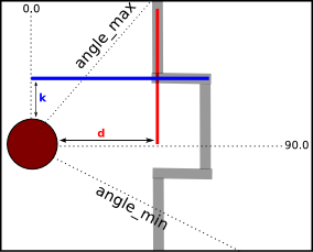
Next to a door that is located in a dead end, a door will be detected in the walls of the maze. This detection is implemented using laser data ranges on both sides of PICO. These ranges are from 15 to 120 degrees on the left of the robot and from -15 to -120 degrees on the right side with a range of 2.0 meters. Using the laser beams and the Pythagorean theorem as described in the Alignment section, distance ‘d’ is calculated for recognizing so-called vertical walls of the maze. A vertical wall is defined as the set of consecutive laser data points that have a value for ‘d’ within a certain uncertainty limits. When a distance ‘d’ is calculated that is not within these limits, PICO is recognizing a horizontal wall. For these horizontal walls, the same idea is applied as for the vertical walls, only now for determining distance ‘k’ using the laser beams and the Pythagorean theorem. In Figure | Next to a door that is located in a dead end, a door will be detected in the walls of the maze. This detection is implemented using laser data ranges on both sides of PICO. These ranges are from 15 to 120 degrees on the left of the robot and from -15 to -120 degrees on the right side with a range of 2.0 meters. Using the laser beams and the Pythagorean theorem as described in the Alignment section, distance ‘d’ is calculated for recognizing so-called vertical walls of the maze. A vertical wall is defined as the set of consecutive laser data points that have a value for ‘d’ within a certain uncertainty limits. When a distance ‘d’ is calculated that is not within these limits, PICO is recognizing a horizontal wall. For these horizontal walls, the same idea is applied as for the vertical walls, only now for determining distance ‘k’ using the laser beams and the Pythagorean theorem. In Figure 9, a schematic overview of both the horizontal and vertical walls and distanced ‘d’ and ‘k’ is shown. | ||
When PICO detects a horizontal wall after it is detecting a vertical wall, a corner is identified. This also counts when PICO detects a vertical wall after a horizontal wall. When four corners are detected at the same time, as shown in the figure above, a possible door is detected. For this detection of the four corners, a range of the length of the laser beams is set. | When PICO detects a horizontal wall after it is detecting a vertical wall, a corner is identified. This also counts when PICO detects a vertical wall after a horizontal wall. When four corners are detected at the same time, as shown in the figure above, a possible door is detected. For this detection of the four corners, a range of the length of the laser beams is set. | ||
After detecting the four corners of a possible door at the side of PICO, it will continue driving forward until it recognizes two corners only. This means that corners | After detecting the four corners of a possible door at the side of PICO, it will continue driving forward until it recognizes two corners only. This means that corners two are out of range of the laser beams used for door detection and that PICO is positioned in front of the door. | ||
After PICO has positioned itself in front of a possible door, a bell is rung and the same steps will be performed as for the front door detection. When PICO after five seconds recognizes the door has not been opened, and therefore is not a door, it will continue the maze solving algorithm. In the case where the door has been opened, PICO will notice the door no longer as a door but as a gap. Next, the maze solving algorithm will turn the robot towards the opened door, commands it to drive through it and continues solving the maze. | After PICO has positioned itself in front of a possible door, a bell is rung and the same steps will be performed as for the front door detection. When PICO after five seconds recognizes the door has not been opened, and therefore is not a door, it will continue the maze solving algorithm. In the case where the door has been opened, PICO will notice the door no longer as a door but as a gap. Next, the maze solving algorithm will turn the robot towards the opened door, commands it to drive through it and continues solving the maze. | ||
| Line 192: | Line 198: | ||
'''''Wall detection''''' | '''''Wall detection''''' | ||
The first approach to process the laser data was to extract walls from it. This was done by looking at consecutive points who are close enough to each other to be the same wall. With this function | The first approach to process the laser data was to extract walls from it. This was done by looking at consecutive points who are close enough to each other to be the same wall. With this function separate walls could be detected when the distances between points are large enough, as can be seen in Figure 10. In this figure every color is a set of points belonging to on wall. This way of detecting walls neglects the corners as shown in Figure 11. Therefore it is tried to calculate the direction between two consecutive points to determine if it is one straight wall. The implementation of this part has never worked as it should. A reason could be that the noise between two consecutive points are to much at some point. | ||
<table style="width:100%"> | |||
<td> | |||
[[File:walldetect_5_2017.png|400px|thumb|center|Figure 10: Separate walls detected.]] | |||
</td> | |||
<td> | |||
[[File:walldetect2_5_2017.png|400px|thumb|center|Figure 11: No corners detected.]] | |||
</td> | |||
</table> | |||
[[File:cornerdetection_5_2017.png|300px|thumb|right|Figure 12: Corner detection method.]] | |||
'''''Corner detection''''' | '''''Corner detection''''' | ||
To identify the corners which could not be detected by the initial wall detection | To identify the corners which could not be detected by the initial wall detection, the following algorithm is implemented. | ||
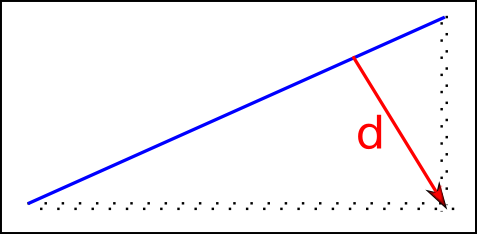
Take a range of a certain amount of consecutive points. Draw an imaginary line between the first and the last point of the range. Calculate for each point in between the lateral distance to the imaginary line. When the distances are below a threshold there is no corner in this piece of wall. When there is at least one distance larger than the threshold it is a | Take a range of a certain amount of consecutive points. Draw an imaginary line between the first and the last point of the range shown in Figure 12 by the blue line. Calculate for each point in between the lateral distance to the imaginary line. When the distances are below a threshold there is no corner in this piece of wall. When there is at least one distance larger than the threshold it is a corner. If there are more than one larger distances the furthest point is the corner point, this is represented in Figure 12 by the red arrow. When there is no corner detected in the current range the range is shifted one point further. When a corner was detected the next range begins with the corner point. This approach seemed to work for some corners, but the corner points were too unstable. Sometimes it did not see corners when PICO was really close to the corner. It is tried to tune the algorithm, but in the end it will not be used. | ||
This approach seemed to work for some corners, but the corner points were too unstable. Sometimes it did not see corners when PICO was really close to the corner. | |||
== Movement Controller == | == Movement Controller == | ||
| Line 207: | Line 220: | ||
=== Potential Field === | === Potential Field === | ||
[[File:PotentialField 201705.PNG|250px|thumb|right|Figure 13: Attractive and repulsive forces for the potential field.]] | |||
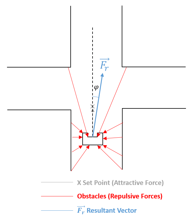
In order to move PICO through the maze avoiding the walls and towards the exit, potential field is used which is a type of behavior-based robotics. These actions or behaviors most of the time are stimulus-responses, a reaction to some world stimulus (walls/obstacles) and generates an action in response of this stimulus (stop, move right, move left, etc.). | In order to move PICO through the maze avoiding the walls and towards the exit, potential field is used which is a type of behavior-based robotics. These actions or behaviors most of the time are stimulus-responses, a reaction to some world stimulus (walls/obstacles) and generates an action in response of this stimulus (stop, move right, move left, etc.). | ||
Potential field consist of a resulting force/vector, obtained after attractive and repulsive forces are taking into consideration, which corresponds to the speed and desired angle of the movement desired for PICO. Obstacles and walls have a repelling force, while the set point gives an attracting force. | Potential field consist of a resulting force/vector, obtained after attractive and repulsive forces are taking into consideration, which corresponds to the speed and desired angle of the movement desired for PICO. Obstacles and walls have a repelling force, while the set point gives an attracting force. | ||
The repulsive forces are computed for every laser point available using equation below and decomposed into x and y components using its respective angle. For the attraction force, only the set point is considered, in our case, the attraction force is always the same given the fact that potential field is not being used to make the rotation movement, e.g.set point is the same all the time. | The repulsive forces are computed for every laser point available using equation below and decomposed into <math>x</math> and <math>y</math> components using its respective angle. For the attraction force, only the set point is considered, in our case, the attraction force is always the same given the fact that potential field is not being used to make the rotation movement, e.g.set point is the same all the time. | ||
[[File:EquationFrep 201705.PNG|400px|center]] | |||
where b is a gain constant used to tune the behavior of PICO. For this particularly constant, the tuning had to be made with real PICO as the simulation and reality were really different for this tuning. Finally the resulting components in x and y are saturated within the physical or permitted limits. | where <math>b</math> is a gain constant used to tune the behavior of PICO. For this particularly constant, the tuning had to be made with real PICO as the simulation and reality were really different for this tuning. Finally the resulting components in <math>x</math> and <math>y</math> are saturated within the physical or permitted limits. The designed potential field function can be found '''[https://gitlab.com/emc2017/group5/snippets/1665475 here]''' and a visualization of the potential field is shown in Figure 13. | ||
=== Rotations === | === Rotations === | ||
The specifications for the maze challenge specify that within the maze only walls are approximately axis-aligned, meaning there are only right angles (or 180). For making the 90 and 180 degrees turn, odometer data is used | The specifications for the maze challenge specify that within the maze only walls are approximately axis-aligned, meaning there are only right angles (or 180). For making the 90 and 180 degrees turn, odometer data is used, howver presents some error to make this turns and if it’s not considered PICO will end up accumulating this error at every turn (error is solved with the '''[http://cstwiki.wtb.tue.nl/index.php?title=Embedded_Motion_Control_2017_Group_5#Alignment alignment function]'''). The main idea is that when Action Manager determines that a turn either right, left or turn around must be performed PICO stops and the odometer data is captured (doesn’t matter the original value), then the angular velocity is given to PICO starting the rotation, the new odometer data is checked at every instant and compared with original position until the rotated angle is 90 degrees. | ||
=== Unused functions=== | |||
[[File:Virtwall.gif|200px|frame|right|Figure 14: Open spaces with and without virtual walls]] | |||
'''''Variable Setpoint''''' | |||
After potential field was working, one idea was to use it to make the turning by using the angular velocity and changing the set point in the middle of the corridor either right or left, or behind PICO for a 180° degree and the potential field automatically will go in that direction avoiding walls. This function was not used because at the moment result really time consuming to compute the variable set points. Since only 90° turns are needed, it would be sufficient using the odometer data. | |||
'''''Virtual Corridor''''' | |||
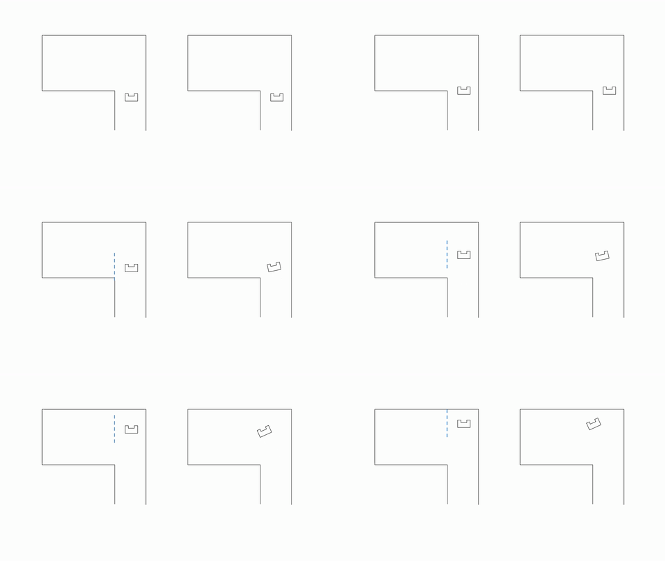
When implementing the motion control, it is found out that while driving forward PICO moves away of the wall when driving through open spaces, which happens because of the potential field when computing the resulting force. The "free" space was more attractive than keep going forward, which causes the missing of some turns in some cases. One solution to avoid this was the "Virtual Corridor" function. The idea of this function was that when PICO was located in open spaces, the robot thought it was in a corridor by adding some "virtual walls" instead of the open space, causing that PICO will keep a straight forward direction. Even when the implementation worked on simulation, it was only possible to try it once in the real world with not sufficient time (tuning was needed) so this idea was abandoned as it did not work at first try. In Figure 14 an animation of this function is shown. | |||
== Action Manager == | |||
[[File:ActionManager.jpg|200px|thumb|right|Figure 15: Overview of Action Manager class]] | |||
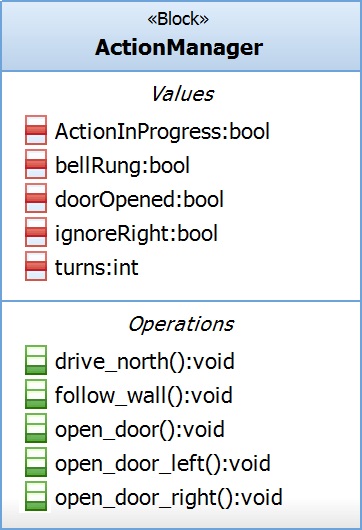
The action manager’s purpose is to decide which action to perform next depending on the current perception of the world (see Figure 4). It will do so based on the Pledge algorithm, which was explained '''[http://cstwiki.wtb.tue.nl/index.php?title=Embedded_Motion_Control_2017_Group_5#Maze-solving_Algorithms here]'''. It has been arbitrarily chosen that within this algorithm a right hand wall follower is used. Figure 15 shows that the module utilizes five attributes and five operations (states) in its behaviour. | |||
=== Attributes === | |||
Besides the input from the WorldSkills, the following five attributes are utilized: | |||
'''ActionInProgress'''<br/> | |||
A boolean which indicates whether or not an action is currently being executed by the movement controller. This is implemented as a safeguard to prevent the action manager from issuing new commands to the movement controller while it is still performing an action, for example, a turn. This boolean is reset to false by the movement controller when it has finished its maneuver. | |||
<code> | |||
if(!actionInProgress) | |||
{ | |||
:… | |||
:else if(leftFree) | |||
:{ | |||
::stateMove = take_left_exit; | |||
::actionInProgress=true; | |||
::… | |||
:} | |||
…<br/> | |||
}</code> | |||
'''bellRung'''<br/> | |||
A boolean to store whether or not the bell to request the opening of a door has been rung. This is necessary to make sure PICO rings only once after detecting an alleged door, instead of in every cycle: | |||
<code> | |||
if(!bellRung) | |||
{ | |||
:io.sendOpendoorRequest(); | |||
:bellRung=true; | |||
}</code> | |||
'''doorOpened'''<br/> | |||
A boolean that keeps track of whether or not a door has been opened already. As it is stated in the Maze Challenge specifications that there is only one door in the maze, it would be a waste of time ringing to try and open a second potential door. This attribute is used in many conditions considering door detection and state changes. All of these states become unavailable if this boolean is set to true. | |||
<code> | |||
if(doorLeft && !doorOpened) | |||
{ | |||
:statePledge=open_door_left; | |||
:… | |||
}</code> | |||
'''ignoreRight'''<br/> | |||
[[File:IgnoreRight.png|300px|thumb|right|Figure 16: Ignore right illustration]] | |||
A boolean that prevents PICO from turning back at a junction. Because a right hand wall follower is used, turning towards a right gap is preferred over moving forward. This leads to the following behavior: PICO | |||
* detects a gap to its right, | |||
* turns towards the gap, | |||
* detects a gap to its right (corridor it just came from) and | |||
* PICO turns back towards the corridor it came from. | |||
This boolean attribute prevents such behavior by disabling turning right twice in a row. This functionality is illustrated in Figure 16. | |||
<code> | |||
else if(rightFree&&!ignoreRight) | |||
{ | |||
:stateMove = take_right_exit; | |||
:ignoreRight=true; | |||
:… | |||
}</code> | |||
'''turns'''<br/> | |||
This integer is vital for the functionality of the Pledge algorithm. It indicates PICO’s orientation relative to the initial north heading. For every right turn, a value of 1 will be added and for every left turn, 1 will be subtracted. This means that when the value is either 2 or -2, PICO is oriented in the exact opposite direction (180 degrees) as it was initially. It is also important that the value of the integer is not limited in either positive or negative direction, even though PICO will be oriented in the same direction for values of 0, 4, 8, -4, -8… This means PICO will keep following a wall unless the counter goes exactly to zero. | |||
<code> | |||
else if(leftFree) | |||
{ | |||
:stateMove = take_left_exit; | |||
:turns--; | |||
:… | |||
}</code> | |||
=== States === | |||
[[File:statePledge2.jpg|500px|thumb|right|Figure 17: Main Action Manager state machine.]] | |||
The action manager uses a state machine to switch among five states: | |||
* Drive north | |||
* Follow wall | |||
* Open door left | |||
* Open door right | |||
* Open door front | |||
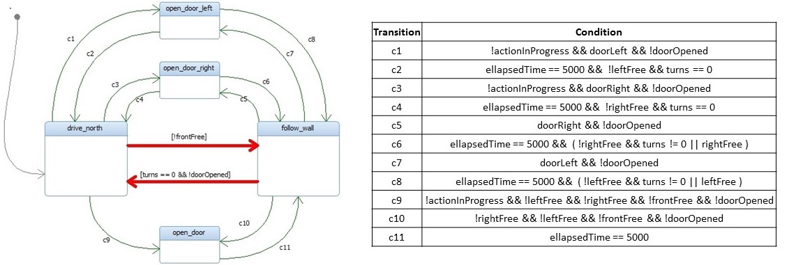
Drive north and Follow wall are the two states that are used by the Pledge algorithm and control PICO’s movement through the maze. The three Open door states are only accessed when a possible door is detected and are always followed up by either Drive north or Follow wall. A state machine diagram depicting this behavior is shown in Figure 17. Here, one can easily distinguish the main transition (colored red) and the transitions that occur only when a door is detected (green). Also note that the green transitions are only possible while the attribute doorOpened is false. | |||
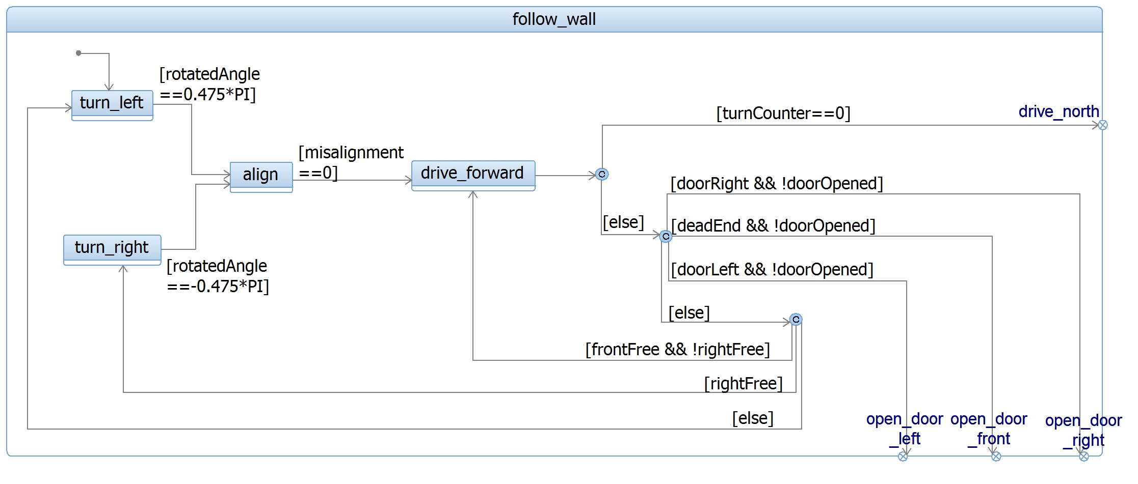
Initially the system starts in the drive_north state, thereby defining its preferred heading. In this state, PICO will drive forward as far as possible and will disregard any left or right exits. Only when PICO detects a front wall from the WorldSkills (frontFree == false), the state will switch to follow_wall. This state is pretty self-explanatory and will follow the wall on its right hand, meaning that the first manoeuvre will be to turn left. Within follow_wall, the priorities for taking actions are as follows: | |||
# Turn right | |||
# Drive forward | |||
# Turn left | |||
As explained previously, the attribute turns will change on every rotation. In the case that this integer returns to 0, PICO knows it is heading in the initial "north" direction and returns to the drive_north state. | |||
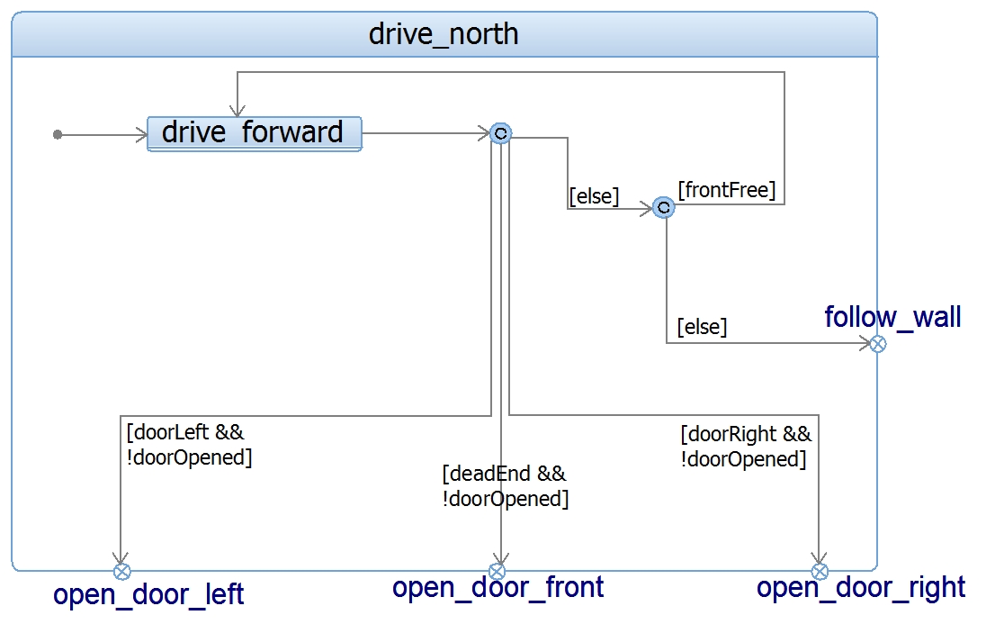
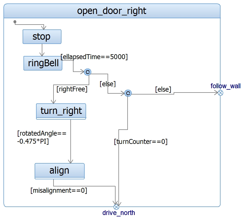
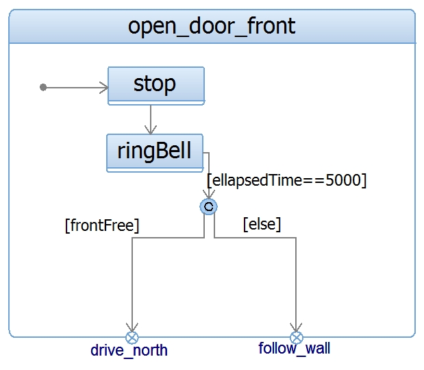
Although the conditions for state transitions have been briefly presented in Figure 17, a more extensive explanation could be helpful. Therefore, Figures 18 to 22 show internal state-machines for each state in the Action Manager. These internal state-machines are composed of decision nodes, internal actions and actions executed by the Movement Controller. | |||
[[File:drive_north.jpg|400px|thumb|left|Figure 18: Drive_north state machine.]] | |||
[[File:follow_wall.jpg|600px|thumb|center|Figure 19: Follow_wall state machine.]] | |||
[[File:door_right.jpg|335px|thumb|right|Figure 21: Open_door_right state machine.]] | |||
[[File:door_left.jpg|300px|thumb|left|Figure 22: Open_door_left state machine.]] | |||
[[File:door_front.jpg|350px|thumb|center|Figure 20: Open_door_front state machine.]] | |||
==== Wall following after door opening ==== | |||
[[File:DriveNorthDisabled.png|300px|thumb|right|Figure 23: Drive_north disable illustration.]] | |||
An important design feature is that after the door has been opened, PICO will stay in the follow_wall state forever, instead of resuming the driving_north state when the turn counter goes to zero. Since there is only one door in the maze and the exit can only be reached after going through the door, PICO is guaranteed to exit the maze using the wall follower only. Staying in this state for the rest of the challenge will save time by preventing PICO from turning back through the door. Furthermore, PICO does not stop to ring any potential doors once it has detected a door has been opened. Figure 23 shows a scenario in which PICO will turn back through the door and how it is solved by disabling drive_north after passing through the door. | |||
==== Integration with Movement Controller ==== | |||
A state machine is used to intertwine the Action Manager and the Movement Controller. To properly map the links from the Action Manager to the Movement Controller, the table in Figure 24 is introduced. This table shows which states are commanded '''''by''''' the Action Manager '''''to''''' the Movement Controller and under which condition. Within the state drive_north, for instance, the movement controller can only take one of the three states drive_forward, take_left_exit and stop. The conditions for these transitions are noted inside the cells and numerated in order of priority. This means that first the conditions for a side door will be checked (1 & 2), then the conditions for driving forward (3) and finally the conditions for a dead end with (4) and without (5) a potential door. It is also important to note that this table only gives the relations between Action Manager and Movement Controller. These conditions can also result in internal state changes; For instance, frontFree invokes the drive_forward state of the Movement Controller from the drive_north state, but also leads to the transition from drive_north to follow_wall in the Action Manager state machine (see Figure 17). | |||
[[File:StateTable.png|800px|thumb|center|Figure 24: Action Manager linkage to Movement Controller.]] | |||
Also note that the open_door_front state shows no else condition in the table. In case of this else (when a door has been opened), the Action Manager's state switches to follow_wall and decides the next Movement Controller state from there. This behaviour can not be illustrated in Figure 24, but is instead shown in Figure 17. | |||
= Testing sessions = | |||
This section describes the progress made during the testing sessions. A general outline of the process is given, followed by a more detailed report per session. | This section describes the progress made during the testing sessions. A general outline of the process is given, followed by a more detailed report per session. | ||
| Line 233: | Line 377: | ||
During this phase of the project the main objective for PICO was to: | During this phase of the project the main objective for PICO was to: | ||
* drive forward with | * drive forward with stability, | ||
* detect a perpendicular corridor to its left or right | * detect a perpendicular corridor to its left or right and | ||
* turn towards this exit and continue forward. | * turn towards this exit and continue forward. | ||
It turned out that keeping PICO from bumping into the maze’s walls could be achieved relatively easy by the use of the potential fields. More issues were encountered in making PICO detect the side gaps and making him stop approximately in the center of the junction. Initially, an algorithm was used that would give a trigger the instant that a gap is detected, which happened tens of centimeters before the actual junction | It turned out that keeping PICO from bumping into the maze’s walls could be achieved relatively easy by the use of the potential fields. More issues were encountered in making PICO detect the side gaps and making him stop approximately in the center of the junction. Initially, an algorithm was used that would give a trigger the instant that a gap is detected, which happened tens of centimeters before the actual junction. After adapting the algorithm to only use a part of the LRF’s range and iteratively tuning its parameters, PICO was able to stop before the center of the exit. | ||
When the corner had been detected, PICO was commanded to turn 90 degrees to the left or right. This maneuver, however, turned out to be more difficult than expected; It seemed that PICO’s rotated angle could range between approximately 70 and 110 degrees, when the movement was based on the odometry data | When the corner had been detected, PICO was commanded to turn 90 degrees to the left or right. This maneuver, however, turned out to be more difficult than expected; It seemed that PICO’s rotated angle could range between approximately 70 and 110 degrees, when the movement was based on the odometry data. This kind of misalignments would cause PICO to crash into the side walls, hence different approaches were tried. Finally, an algorithm that would make PICO start rotating on command and stop rotating when it detects that the beams in front of him read a minimum distance, seemed the most suitable in simulation. | ||
The code for the action manager was fairly simple, as its only job was to give the turn left or right command depending on where the gap was detected. No problems or struggles occurred during any test session with this module. | The code for the action manager was fairly simple, as its only job was to give the turn left or right command depending on where the gap was detected. No problems or struggles occurred during any test session with this module. | ||
== | === Phase 2: Pre-maze challenge === | ||
During the corridor challenge, it was observed that using time delays for rotations was not a good option in real-life testing. Hence, instead of using time-delays, odometry data was decided to be used to achieve 90° rotations. | |||
The | The very first test in Phase 2 was to test rotations with odometry data. In order to do so, a program was prepared such that PICO rotates 90° around itself and stops. By repeating this test, some parameters were tuned and it was observed that in spite of some error, odometry worked good enough to make rotations. Then, another program was run in order to test corridor challenge with odometry data rotations and PICO solved corridor challenge. Even though corridor challenge was done, there were some problems regarding the position where PICO stopped and the amount of rotation PICO made while turning to right or left. The problem related with stopping position was originated from gap detection algorithm and the problem related with the amount of rotation was coming from odometry data. | ||
In order to solve problem related with stopping position, several tests were done to tune the parameters that are related with Laser Range Finder. During the tests, PICO was detecting the exit either too early or too late and stopping at that wrong position. By trial and error, optimum parameters were found and this problem was solved. Also gap detection range was adjusted in one of the test sessions by building a tapered maze with increasing width of a corridor. In this test, different parameters were tried and the best-fit was found. | |||
In order to solve problem related with error in rotation, a new function called allignment was created and this function was tested. During the tests, first PICO was placed in between two walls and the function worked properly. Then PICO was placed into a T-junction but this time the function made PICO wobbling continously. Furthermore, PICO was placed in between a corridor and a T-junction but again there was a problem and PICO stopped moving. The same problem was also observed when PICO was placed next to a one wall. Lastly, PICO was placed in a dead end and the function worked properly. After trying almost all the possible situations, lessons were learned and the allignment function was improved accordingly. | |||
As the maze challenge has a door that has to be opened to finish the maze, a functionality is required. The requirement is the following. PICO should be able to detect a dead end and request a possible door to be opened. When the door is opened, it should pass on and when no door is opened in time PICO should turn around and continue the algorithm. After this function is created, a test was executed in two stages. First, PICO drives through a corridor and encounter a dead end. PICO should stop and request the door to be opened. After 5 seconds, PICO turns around and exit the corridor on the other side. In the second scenario PICO drives up to the dead end, which is removed when the request is issued. As soon as the object is removed, PICO should drive forward and continue the corridor. When the second dead end is encountered, PICO will turn around immediately without requesting and he will exit the corridor at the other end. This plan was applied in testing with doors placed to both left and right with different depths (20-40-60 cm wide) Fortunately, door detection worked properly. | |||
Potential field is used in the movement controller of PICO and until the last week of tests, parameters related with potential field were tuned. The reason of tuning these parameters during many testing sessions was that PICO in real testings was not behaving as in simulations. Hence, continous development in potential field was required and the major development was achieved by tuning the parameters related with the effect of repulsive forces on the speed of PICO. | |||
Final rehersal was done one day before the maze challenge and the complete code was run in a maze that was built by our group. Fortunately, PICO solved the maze several times with all functions were working almost perfectly. | |||
== | = Corridor Challenge = | ||
=== Plan & Expectations === | |||
The strategy for the corridor challenge was to drive forward as fast as possible with potential field as controller to keep PICO in the middle of the corridor. While driving through the corridor the sides are continuously checked for gaps using ranges of laser data to the left and right of PICO. These ranges are tuned during experiment sessions. When a gap is detected PICO stops for a moment and has to turn 90 degrees to the side of the gap. | |||
The initial idea was to use the odometry data for this purpose, but from testing results it seemed that this data was not reliable enough to let PICO turn. For this reason it is chosen to implement turning that is based on time delay using a for loop (see the code below) and that PICO would be stopped as soon as he detected that his front was clear, facing the exit corridor. The amount of iterations is also tuned in simulation. When the turn is completed PICO will drive forward again as it did before the turn. In Figure 25, the simulation of PICO driving through the corridor, finding an exit and exiting it is shown. | |||
<code>PICO start turning{ | |||
:For x iterations (where x is around 25000) | |||
::Keep turning | |||
:PICO stop turning | |||
}</code> | |||
[[File:corridor_simulation_5_2017.gif|frame|center|400px|Figure 25: Simulation of Corridor Challenge.]] | |||
=== Results & Discussion === | === Results & Discussion === | ||
During the corridor challenge driving forward controlled with the potential field worked as expected. There were some minor side movements which could be tuned for the future, but overall the potential field worked fine. The gap was detected and also at the right time, that is when PICO was standing in front of the gap. PICO stops and started turning, but it never stopped turning during the corridor challenge as can be seen in the left video below. | |||
This failure was caused by the for-loop delay, the time PICO had to turn. This delay was tuned in the simulator, but on PICO it did not work as simulated. It is discovered that PICO does not behave exactly as in the simulator, and that a for loop delay is based on CPU time, which is depending on the computer or state of the computer. Also turning based on a delay is not as robust as using the sensor data. For the maze challenge the turning has to be improved. It was concluded to take out the time-based events and abandon their use for the remainder of the project. | |||
Before the actual corridor challenge we tested the code for turning using odometry, as can be seen in the right video. This appeared to be a lucky shot because in the next test the turn was not accurate enough, so it bumped into the wall. Therefor we had to adapt our code between testing and the actual maze challenge. | |||
<table style="width:100%"> | <table style="width:100%"> | ||
<td> | <td> | ||
''''' | <center> | ||
'''''Recording of the corridor challenge''''' | |||
{| | {| | ||
|[[File: | |[[File:Corridortesting_EMC2017G5.jpg|left|400px|link=https://youtu.be/b4lpJyrapU8]] | ||
|} | |} | ||
</center> | |||
</td> | </td> | ||
<td> | <td> | ||
''''' | <center> | ||
'''''Testing of the code before the corridor challenge''''' | |||
{| | {| | ||
|[[File: | |[[File:corridorchallenge_EMC2017G5.jpg|center|400px|link=https://youtu.be/LWgbIHCVoRc]] | ||
|} | |} | ||
</center> | |||
</td> | |||
</table> | |||
= Maze Challenge = | |||
=== Plan & Expectations === | |||
PICO was expected to drive based on the pledge algorithm with a right hand wall follower, continuously looking for possible doors. When PICO found a door that opens, it will stop checking for doors because there can only be one door opened. Also the initial direction of the pledge algorithm is reset after going through the door. Because of the implemented algorithm PICO should always exit the maze. The time PICO will take to find the exit depends on the layout of the maze. | |||
It is expected that PICO will drive relatively fast towards the exit of the maze without bumping into walls, because of the high speed and tuned potential field parameters. After every turn PICO makes it will be aligned to the surrounding walls. Below, two videos are presented of simulations when PICO drives through the maze of the final challenge with the exact same code as used during the maze challenge in the left video and an improved version of this code in the right one. | |||
<table style="width:100%"> | |||
<td> | |||
<center> | |||
'''''Simulation of the maze challenge code''''' | |||
[[File:simmaze_group5.jpg|center|400px|link=https://youtu.be/pOiPKfaZxwY]] | |||
</center> | |||
</td> | |||
<td> | |||
<center> | |||
'''''Simulation of the maze challenge code with improvements''''' | |||
[[File:simmaze_group5.jpg|center|400px|link=https://youtu.be/V-hDb3GWXpM]] | |||
</center> | |||
</td> | </td> | ||
</table> | </table> | ||
== Meetings Overview | === Results & Discussion === | ||
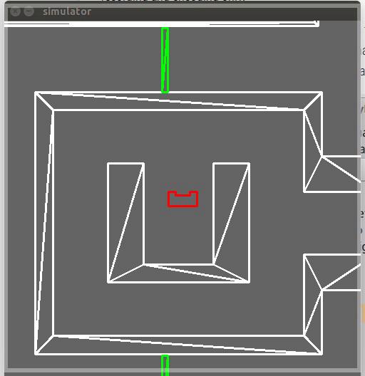
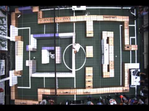
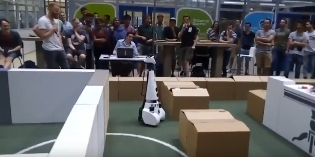
During the maze challenge PICO was executing the implemented Pledge algorithm with a right hand follower. It was also checking for doors in the walls of the maze continuously. As can be seen in the video of the top view of the maze challenge below, PICO finds a door and rings a bell so that this door opens. After this door has been opened, PICO defines its driving direction as the initial direction. When the robot bumps into a wall, the right wall follower is engaged and PICO starts following this wall. Unfortunately, PICO got stuck in a deadlock situation and therefore was not able to exit the maze. A top-view recording of both attempts when PICO tried to find the exit of the maze is shown in the left video below. In the right video, a recording of PICO during the maze challenge is presented that is recorded from the side of the maze. | |||
<table style="width:100%"> | |||
<td> | |||
<center> | |||
'''''Recording of the maze challenge (top view) ''''' | |||
[[File:recordmaze_group5.jpg|center|450px|link=https://youtu.be/N0vDxW5b3no]] | |||
</center> | |||
</td> | |||
<td> | |||
<center> | |||
'''''Recording of the maze challenge (side view) ''''' | |||
[[File:Capture_maze_footage.PNG|center|555px|link=https://youtu.be/gq0ohgf2nEE]] | |||
</center> | |||
</td> | |||
</table> | |||
To identify the problem that occurred in the real maze during the final challenge, both the simulation video as shown above and the recorded video of the maze challenge are compared. An extensive description of the these videos with PICOs actions can be found on the '''[http://cstwiki.wtb.tue.nl/index.php?title=Maze_simulation maze simulation]''' page for the simulation and on the '''[http://cstwiki.wtb.tue.nl/index.php?title=Maze_recording maze recording]''' page for the top-view recording, which are listed with according time stamps. From the analysis of both videos, it can be concluded that there are a number of differences in the behaviour of PICO. | |||
Below the differences between the simulation with the maze challenge code '''''without''''' improvements and recording of the maze challenge are depicted: | |||
*In the beginning of the simulation PICO detects a fake door to the right (0:04), compared to nothing in the real maze (0:04). | |||
*When PICO has found its way out of the internal square, PICO moves sidewards in the simulation (0:19) and turns left during the maze challenge for both attempts (0:48 and 4:32). | |||
*In the simulation PICO opens the first door and ignores it instead of driving through it (0:33). During the maze challenge, PICO opens the same door and drives through it in both attempts (attempt 1: 1:24 and attempt 2: 5:11). | |||
*Furthermore, PICO gets in a deadlock state when it almost has reached the exit of the maze. This makes the robot decide to go back into the maze and repeats this several times until it is stopped by the user. During the second attempt the same happens twice, after which PICO gets out of the deadlock state (6:37) and continues its way. Unfortunately, the challenge is stopped due to the time limit. | |||
A reason for PICO behaving the way as it did during the maze challenge is that the initial direction is reset after a door has been detected. As can be seen in the recordings, PICO detects a door and rings the bell in both attempts just before exiting the internal square of the maze (attempt 1: 0:48 and attempt 2: 4:32). When the robot moves through this fake door, the 'North direction' is reset and PICO drives forward until the next wall in front is reached and the right-hand following is started. In the simulation simulation, PICO does not detect a door here and therefore continues to follow the wall to its right. | |||
The deadlock state in which PICO gets when it is nearing the exit of the maze can be declared by an incorrect implementation of the detection dead ends. At the point where PICO gets into the deadlock state, this implementation possibly influenced the Pledge algorithm by detecting dead ends instead of 90° corners. During the second attempt PICO finally gets out of the deadlock state, which can be explained by a little different position compared to the first attempt, which then causes PICO to deploy an alignment maneuver. After this, the Pledge algorithm continued with the right-hand following. | |||
= Recommendations for future work = | |||
After analyzing the results from the Corridor and Maze challenges, opportunities for future work can be identified. | |||
First, a more robust implementation of dead end detection is required because the current one produces false positives. Tuning the free space detection around the robot is required to overcome this error. Similarly, the door detection to the left and right also requires further testing and tuning to prevent missing shallow dead ends and to avoid false positives. | |||
A more optimal algorithm would allow PICO to exit the maze faster. Therefore, the next step would be to implement more advanced techniques such as the Trémaux Algorithm explained above. Of course this would require an additional level of abstraction in which the WorldSkills evolve into a WorldMap which is able to identify those intersections that have been visited already. This would also require mapping techniques such as Simultaneous Localization and Mapping and possibly the use of a Kalman filter to integrate the input from odometry, laser, and a mathematical model to derive a more accurate estimation of the robot's position. | |||
Further testing to better tune the artificial potential field could also be helpful. This would allow to implement more aggressive maneuvers without the risk of bumping into walls. As of now, longitudinal and angular displacements were not used simultaneously. The current implementation of the artificial potential field allows for the computation of a desired angular speed based on the summation of all artificial forces. This could be used to drive the robot around corners just by placing the attractive force around the corner, instead of splitting the maneuver into turning and then driving forward. This would also require the detection of corners from World Skills so as to place the target point in an adequate position around the corner. Combining angular and forward speed will reduce the time required to take corners but it also increases the chance of hitting the corners if not tuned and tested thoroughly. | |||
= Code Excerpts = | |||
This section contains some excerpts of the code from the PICO Maze Controller. Code that was considered to give an overview of the system is listed below: | |||
*The code for the alignment function, which is used to align PICO after every turn, can be found '''[https://gitlab.com/emc2017/group5/snippets/1665376 here]'''. | |||
*The code for the potential field function, which is used to prevent PICO from bumping into walls, can be found '''[https://gitlab.com/emc2017/group5/snippets/1665475 here]'''. | |||
*The code for the main.cpp file, which includes the Action Manager state machine, can be found '''[https://gitlab.com/emc2017/group5/snippets/1665569 here]'''. | |||
= Meetings Overview = | |||
Brief summaries on the contents of team meetings are available | Brief summaries on the contents of team meetings are available '''[http://cstwiki.wtb.tue.nl/index.php?title=Embedded_Motion_Control_2017_Group_5_Meetings_Overview here]'''. | ||
Latest revision as of 21:00, 21 June 2017
This page describes the development of the PICO maze controller for the course 4SC020 Embedded Motion Control. The objective of the project is to design a controller for PICO, a mobile robot equipped with a holonomic base, wheel encoders and a laser range finder (LRF). This controller shall enable PICO to autonomously navigate through a random maze without bumping into walls. The designed system receives data from the wheel encoders and the LRF which is then used to decide what movement commands will be requested to the holonomic base. In Figure 1, an overview of the context of the system is shown.
Members Group 5
| Name | Student ID | |
| Torben Beernaert | 0778690 | t.f.beernaert@student.tue.nl |
| Rodrigo Estrella Treviño | 1035228 | r.estrella.trevino@student.tue.nl |
| Kagan Incetan | 1037760 | k.incetan@student.tue.nl |
| Sjoerd Knippenberg | 0738104 | s.c.m.knippenberg@student.tue.nl |
| Angel Molina Acosta | 1036456 | a.molina.acosta@student.tue.nl |
| Bart Vercoulen | 0747283 | b.c.g.vercoulen@student.tue.nl |
Requirements & Specifications
The requirements for the system are deducted from the course page and established from a brainstorm session. The FURPS model is used to group the requirements together in the following aspects:
- Functionality
- Usability
- Reliability
- Performance
- Supportability
A complete list of all requirements can be found in the requirements and specification overview.
Design
This chapter describes the design of the PICO controller. It revolves mainly around the final design implementations, but also elaborates on several functions that have remained unused and states evaluations and thoughts about the development of certain features.
Initial Design
The Initial Design document can be found here: Initial_Design_Group5.
Maze-solving Algorithms
Three maze solving algorithms are considered. These are elaborated in the upcoming sections, followed by a comparison and elaborate selection.
Wall follower
This algorithm is very simple to implement since only one rule applies: Follow the wall on either your left or right side (depending on the setting). This wall will be tracked until eventually, an exit is found. The algorithm is guaranteed to work when the robot starts at the entrance of a maze. However, if PICO starts at an arbitrary position it might get stuck in a loop, keeping track of the walls of an ‘island’. Since the case description states that the robot will be start from an arbitrary position and that the maze will contain a loop, this algorithm is risky to use and might not be able to guide the robot to the exit.
Pledge algorithm
The Pledge algorithm is very similar to the wall follower, but contains an upgrade to enable the robot to break free from isolated islands. The robot is given a preference direction (north, south, east or west) and follows this heading until it bumps into a wall. Then, an arbitrary (left or right) wall follower starts and keeps track of the orientation of the robot. This wall follower stops when the robot is heading towards the preference direction again and the orientation is zero degrees. Note that for this case, zero degrees is not equal to 360 degrees. Special care has to be taken when the maze is not made up of straight-angled corners, which is luckily not the case in this specific application. The Pledge algorithm is still fairly simple and guaranteed to find the exit of the maze.
Trémaux algorithm
The Trémaux algorithm is a more efficient, but also more complex algorithm. This algorithm keeps track of where PICO has already been by marking paths between junctions. When a junction is detected, a decision is made based on the markings that are already present on the other paths of the junction. The increased efficiency of the algorithm imposes more dependency on the detection of maze elements and maintenance of a world map.
Selection
It is concluded that the wall following algorithm is not a feasible option, since there is a significant chance that PICO will become stuck in a loop. In this case the robot will never exit the maze, regardless of how robust and fast the controller is. The simplest algorithm that gives a guarantee to solve the maze (of the considered) is the Pledge algorithm. Therefore, it is decided to implement this one in the controller. If there is still time before the maze challenge and if the Pledge algorithm has reached its peak performance, the transition to a Trémaux algorithm will be considered. This algorithm is theoretically capable of solving the maze more quickly but requires a more elaborate world model, which imposes significant additional work load.
System Architecture
This section describes the development of the system architecture. First, the translation from the established requirements to functions the system should perform is covered. These functions are assigned to separate subsystems and the information flow between these subsystems is specified.
Functionality
From the requirements list several functionalities can be extracted, which are arranged using the Task-Skill-Motion hierarchy in Figure 2. In this hierarchy one main task, the most abstract and all-embracing functionality, is specified. In this case the main task is to exit the maze. To perform this task a combination of several subordinate functionalities, the skills, is necessary. Finally, the motions are one level deeper than the skills and contain basic functionalities.
Task
- Exit maze
Skills
- Observe environment
- Determine action
- Manoeuvre PICO
Motions
- Process sensor data
- Open door
- Align
- Turn base
- Drive forward
The relationships between functionalities can be classified as "include" or "extend" types, which complete the hierarchy. An include relationship indicates that the functionality at the arrow tail is a necessary part of the arrow head function, while an extend relationship means that the arrow tail functionality can be a follow-up action of the one on the arrow head.
Subsystems
The previously introduced functionalities are grouped together to create the subsystems WorldSkills, ActionManager and MovementController. Every subsystem will be responsible for executing any of these functionalities. Figure 3 shows that the main system is composed of these three subsystems and the functionalities they are mapped to:
Internal flows
Finally, the information flows between the subsystems are specified. The incoming sensor data is gathered in the WorldSkills module, where it is converted to relevant information about the current situation and position of the robot. The situational information is then sent to the ActionManager, which will decide the upcoming action based on the situation (straight corridor / corner / T-junction etc.). The MovementController will then receive this command from the ActionManager and perform the manoeuvre using raw and processed position data provided by the WorldSkills. The diagram in Figure 4 shows this flow of data through the system.
This diagram also shows various attributes and operations. These are elaborated in the subsystems' respective sections below.
World Skills
Filtering
To be able to process the laser data for detecting gaps, aligning or detecting doors, it is filtered first. Consecutive points have to be within a certain distance from each other, otherwise the points will be ignored. Furthermore, this filtering is used to look at a certain bundle of beams between two specified angles as shown in Figure 5. Also the maximum length of a beam can be specified. When a point is within these boundaries it is considered as a valid point. This valid point is than stored as a coordinate as shown in the lines of code below.
Struct coordinate{
- x double;
- y double;
- orig_r double;
- orig_angle double;
- }
}
Alignment
Guiding PICO to the exit of a maze needs a proper alignment according to the walls. Since the obtained odometry data are not as precise as in the simulations, the robot is aligned after each 90 degrees turn that is made. Important to mention is that the first thing that PICO does when the controller software is started is aligning itself. This is done because the exact position and orientation of the robot in the maze is not known beforehand.
For determining the alignment with respect to walls of the maze, the laser beams of both the left- and right side of PICO are used. The ranges that are used for both sides are from 80 to 100 degrees on the left and from -80 to -100 degrees on the right with 2 meters the maximum length of the beams, as shown in Figure 5.
Using the Pythagorean theorem, the corresponding distance ‘d’ is calculated for each of the laser beams in the range, using its angle and length. When these distances are determined, the averages of the parts 80-90 and 90-100 degrees are determined and divided by another to determine the ratio of misalignment. If PICO is aligned to a wall this ratio is equal to -1. The turning direction can be determined by the ratio is larger or smaller than -1. The amount of misalignment determines also the turning speed, when there is a larger misalignment pico will turn faster. As clarification, Figure 6 is added in which the example as explained before is pictured. Note that in this figure only the outer beams of the range are displayed for illustration.
It can be the case that the robot is in an open space and only notices a wall on one side of the robot. Since PICO is able to align using only one wall, this is not a problem at all. In this case, the range of laser beams on the side where no wall is detected is neglected. The part of the designed controller that is responsible for the alignment of PICO can be found here.
The amount of alignment that is needed for driving through the maze safely, without bumping, is set to a fixed value that is tuned during the testing sessions. Below in Figure 7 it is shown how PICO aligns between two walls of the maze.
Side Free
One of the basic skills that is implemented in the code of the robot controller is detecting if a side is free or not. When a side is free, the algorithm as used in the action manager decides if PICO drives into the free direction or continues its path. For determining if the front of PICO is free, the beams within the range of -5 to 5 degrees are free. For the detection if one or both of the sides of PICO are free, the laser ranges from 110 to 120 degrees on the left and from -110 to -120 degrees on the right or the robot are used, as indicated in Figure 5. For the detection of the free sides of the robot, a range of 0.9 meters is used. Laser beams with an angle or length outside the specified ranges will not be taken into account by PICO.
Door detection
Essential for finding the exit of the maze, a door located in a dead end of a corridor or in a wall has to be opened. In Figure 8, a graphical representation of both these situations is shown. When PICO has detected a dead end, a bell will be rung and the door in the maze will be opened within a time of five seconds. Worth mentioning is that when PICO has opened a door in the maze, it will not ring a bell again when it reaches a dead end or detects a fake door in the side of the walls of the maze.
Front
PICO detects a door in the front by checking front free is negative and checking left and right free at angles 80 to 90 and -80 to -90 degrees respecitvely. When PICO has detected a door in the front and the bell is rung, the timestamp of the laser data corresponding to the moment where the dead end is detected is saved. This timestamp will be checked continuously until the before mentioned five seconds have expired. After these seconds, PICO will check if the front is free, indicating the door is open and the maze solving algorithm will continue. When PICO detects that the ‘door’ has not been opened and that the dead end is still a dead end, the algorithm will continue looking for a door.
Side doors
Next to a door that is located in a dead end, a door will be detected in the walls of the maze. This detection is implemented using laser data ranges on both sides of PICO. These ranges are from 15 to 120 degrees on the left of the robot and from -15 to -120 degrees on the right side with a range of 2.0 meters. Using the laser beams and the Pythagorean theorem as described in the Alignment section, distance ‘d’ is calculated for recognizing so-called vertical walls of the maze. A vertical wall is defined as the set of consecutive laser data points that have a value for ‘d’ within a certain uncertainty limits. When a distance ‘d’ is calculated that is not within these limits, PICO is recognizing a horizontal wall. For these horizontal walls, the same idea is applied as for the vertical walls, only now for determining distance ‘k’ using the laser beams and the Pythagorean theorem. In Figure 9, a schematic overview of both the horizontal and vertical walls and distanced ‘d’ and ‘k’ is shown.
When PICO detects a horizontal wall after it is detecting a vertical wall, a corner is identified. This also counts when PICO detects a vertical wall after a horizontal wall. When four corners are detected at the same time, as shown in the figure above, a possible door is detected. For this detection of the four corners, a range of the length of the laser beams is set.
After detecting the four corners of a possible door at the side of PICO, it will continue driving forward until it recognizes two corners only. This means that corners two are out of range of the laser beams used for door detection and that PICO is positioned in front of the door.
After PICO has positioned itself in front of a possible door, a bell is rung and the same steps will be performed as for the front door detection. When PICO after five seconds recognizes the door has not been opened, and therefore is not a door, it will continue the maze solving algorithm. In the case where the door has been opened, PICO will notice the door no longer as a door but as a gap. Next, the maze solving algorithm will turn the robot towards the opened door, commands it to drive through it and continues solving the maze.
Unused functions
The functions as described below are not used in the final code for the maze challenge.
Wall detection
The first approach to process the laser data was to extract walls from it. This was done by looking at consecutive points who are close enough to each other to be the same wall. With this function separate walls could be detected when the distances between points are large enough, as can be seen in Figure 10. In this figure every color is a set of points belonging to on wall. This way of detecting walls neglects the corners as shown in Figure 11. Therefore it is tried to calculate the direction between two consecutive points to determine if it is one straight wall. The implementation of this part has never worked as it should. A reason could be that the noise between two consecutive points are to much at some point.
Corner detection
To identify the corners which could not be detected by the initial wall detection, the following algorithm is implemented. Take a range of a certain amount of consecutive points. Draw an imaginary line between the first and the last point of the range shown in Figure 12 by the blue line. Calculate for each point in between the lateral distance to the imaginary line. When the distances are below a threshold there is no corner in this piece of wall. When there is at least one distance larger than the threshold it is a corner. If there are more than one larger distances the furthest point is the corner point, this is represented in Figure 12 by the red arrow. When there is no corner detected in the current range the range is shifted one point further. When a corner was detected the next range begins with the corner point. This approach seemed to work for some corners, but the corner points were too unstable. Sometimes it did not see corners when PICO was really close to the corner. It is tried to tune the algorithm, but in the end it will not be used.
Movement Controller
The movement controller has the purpose of drive PICO according to the Action Manager decisions without bumping into any wall or obstacle through the way.
Potential Field
In order to move PICO through the maze avoiding the walls and towards the exit, potential field is used which is a type of behavior-based robotics. These actions or behaviors most of the time are stimulus-responses, a reaction to some world stimulus (walls/obstacles) and generates an action in response of this stimulus (stop, move right, move left, etc.). Potential field consist of a resulting force/vector, obtained after attractive and repulsive forces are taking into consideration, which corresponds to the speed and desired angle of the movement desired for PICO. Obstacles and walls have a repelling force, while the set point gives an attracting force. The repulsive forces are computed for every laser point available using equation below and decomposed into [math]\displaystyle{ x }[/math] and [math]\displaystyle{ y }[/math] components using its respective angle. For the attraction force, only the set point is considered, in our case, the attraction force is always the same given the fact that potential field is not being used to make the rotation movement, e.g.set point is the same all the time.
where [math]\displaystyle{ b }[/math] is a gain constant used to tune the behavior of PICO. For this particularly constant, the tuning had to be made with real PICO as the simulation and reality were really different for this tuning. Finally the resulting components in [math]\displaystyle{ x }[/math] and [math]\displaystyle{ y }[/math] are saturated within the physical or permitted limits. The designed potential field function can be found here and a visualization of the potential field is shown in Figure 13.
Rotations
The specifications for the maze challenge specify that within the maze only walls are approximately axis-aligned, meaning there are only right angles (or 180). For making the 90 and 180 degrees turn, odometer data is used, howver presents some error to make this turns and if it’s not considered PICO will end up accumulating this error at every turn (error is solved with the alignment function). The main idea is that when Action Manager determines that a turn either right, left or turn around must be performed PICO stops and the odometer data is captured (doesn’t matter the original value), then the angular velocity is given to PICO starting the rotation, the new odometer data is checked at every instant and compared with original position until the rotated angle is 90 degrees.
Unused functions
Variable Setpoint
After potential field was working, one idea was to use it to make the turning by using the angular velocity and changing the set point in the middle of the corridor either right or left, or behind PICO for a 180° degree and the potential field automatically will go in that direction avoiding walls. This function was not used because at the moment result really time consuming to compute the variable set points. Since only 90° turns are needed, it would be sufficient using the odometer data.
Virtual Corridor
When implementing the motion control, it is found out that while driving forward PICO moves away of the wall when driving through open spaces, which happens because of the potential field when computing the resulting force. The "free" space was more attractive than keep going forward, which causes the missing of some turns in some cases. One solution to avoid this was the "Virtual Corridor" function. The idea of this function was that when PICO was located in open spaces, the robot thought it was in a corridor by adding some "virtual walls" instead of the open space, causing that PICO will keep a straight forward direction. Even when the implementation worked on simulation, it was only possible to try it once in the real world with not sufficient time (tuning was needed) so this idea was abandoned as it did not work at first try. In Figure 14 an animation of this function is shown.
Action Manager
The action manager’s purpose is to decide which action to perform next depending on the current perception of the world (see Figure 4). It will do so based on the Pledge algorithm, which was explained here. It has been arbitrarily chosen that within this algorithm a right hand wall follower is used. Figure 15 shows that the module utilizes five attributes and five operations (states) in its behaviour.
Attributes
Besides the input from the WorldSkills, the following five attributes are utilized:
ActionInProgress
A boolean which indicates whether or not an action is currently being executed by the movement controller. This is implemented as a safeguard to prevent the action manager from issuing new commands to the movement controller while it is still performing an action, for example, a turn. This boolean is reset to false by the movement controller when it has finished its maneuver.
if(!actionInProgress)
{
- …
- else if(leftFree)
- {
- stateMove = take_left_exit;
- actionInProgress=true;
- …
- }
…

}
bellRung
A boolean to store whether or not the bell to request the opening of a door has been rung. This is necessary to make sure PICO rings only once after detecting an alleged door, instead of in every cycle:
if(!bellRung)
{
- io.sendOpendoorRequest();
- bellRung=true;
}
doorOpened
A boolean that keeps track of whether or not a door has been opened already. As it is stated in the Maze Challenge specifications that there is only one door in the maze, it would be a waste of time ringing to try and open a second potential door. This attribute is used in many conditions considering door detection and state changes. All of these states become unavailable if this boolean is set to true.
if(doorLeft && !doorOpened)
{
- statePledge=open_door_left;
- …
}
ignoreRight
A boolean that prevents PICO from turning back at a junction. Because a right hand wall follower is used, turning towards a right gap is preferred over moving forward. This leads to the following behavior: PICO
- detects a gap to its right,
- turns towards the gap,
- detects a gap to its right (corridor it just came from) and
- PICO turns back towards the corridor it came from.
This boolean attribute prevents such behavior by disabling turning right twice in a row. This functionality is illustrated in Figure 16.
else if(rightFree&&!ignoreRight)
{
- stateMove = take_right_exit;
- ignoreRight=true;
- …
}
turns
This integer is vital for the functionality of the Pledge algorithm. It indicates PICO’s orientation relative to the initial north heading. For every right turn, a value of 1 will be added and for every left turn, 1 will be subtracted. This means that when the value is either 2 or -2, PICO is oriented in the exact opposite direction (180 degrees) as it was initially. It is also important that the value of the integer is not limited in either positive or negative direction, even though PICO will be oriented in the same direction for values of 0, 4, 8, -4, -8… This means PICO will keep following a wall unless the counter goes exactly to zero.
else if(leftFree)
{
- stateMove = take_left_exit;
- turns--;
- …
}
States
The action manager uses a state machine to switch among five states:
- Drive north
- Follow wall
- Open door left
- Open door right
- Open door front
Drive north and Follow wall are the two states that are used by the Pledge algorithm and control PICO’s movement through the maze. The three Open door states are only accessed when a possible door is detected and are always followed up by either Drive north or Follow wall. A state machine diagram depicting this behavior is shown in Figure 17. Here, one can easily distinguish the main transition (colored red) and the transitions that occur only when a door is detected (green). Also note that the green transitions are only possible while the attribute doorOpened is false.
Initially the system starts in the drive_north state, thereby defining its preferred heading. In this state, PICO will drive forward as far as possible and will disregard any left or right exits. Only when PICO detects a front wall from the WorldSkills (frontFree == false), the state will switch to follow_wall. This state is pretty self-explanatory and will follow the wall on its right hand, meaning that the first manoeuvre will be to turn left. Within follow_wall, the priorities for taking actions are as follows:
- Turn right
- Drive forward
- Turn left
As explained previously, the attribute turns will change on every rotation. In the case that this integer returns to 0, PICO knows it is heading in the initial "north" direction and returns to the drive_north state.
Although the conditions for state transitions have been briefly presented in Figure 17, a more extensive explanation could be helpful. Therefore, Figures 18 to 22 show internal state-machines for each state in the Action Manager. These internal state-machines are composed of decision nodes, internal actions and actions executed by the Movement Controller.
Wall following after door opening
An important design feature is that after the door has been opened, PICO will stay in the follow_wall state forever, instead of resuming the driving_north state when the turn counter goes to zero. Since there is only one door in the maze and the exit can only be reached after going through the door, PICO is guaranteed to exit the maze using the wall follower only. Staying in this state for the rest of the challenge will save time by preventing PICO from turning back through the door. Furthermore, PICO does not stop to ring any potential doors once it has detected a door has been opened. Figure 23 shows a scenario in which PICO will turn back through the door and how it is solved by disabling drive_north after passing through the door.
Integration with Movement Controller
A state machine is used to intertwine the Action Manager and the Movement Controller. To properly map the links from the Action Manager to the Movement Controller, the table in Figure 24 is introduced. This table shows which states are commanded by the Action Manager to the Movement Controller and under which condition. Within the state drive_north, for instance, the movement controller can only take one of the three states drive_forward, take_left_exit and stop. The conditions for these transitions are noted inside the cells and numerated in order of priority. This means that first the conditions for a side door will be checked (1 & 2), then the conditions for driving forward (3) and finally the conditions for a dead end with (4) and without (5) a potential door. It is also important to note that this table only gives the relations between Action Manager and Movement Controller. These conditions can also result in internal state changes; For instance, frontFree invokes the drive_forward state of the Movement Controller from the drive_north state, but also leads to the transition from drive_north to follow_wall in the Action Manager state machine (see Figure 17).
Also note that the open_door_front state shows no else condition in the table. In case of this else (when a door has been opened), the Action Manager's state switches to follow_wall and decides the next Movement Controller state from there. This behaviour can not be illustrated in Figure 24, but is instead shown in Figure 17.
Testing sessions
This section describes the progress made during the testing sessions. A general outline of the process is given, followed by a more detailed report per session.
Phase 1: Pre-corridor challenge
During this phase of the project the main objective for PICO was to:
- drive forward with stability,
- detect a perpendicular corridor to its left or right and
- turn towards this exit and continue forward.
It turned out that keeping PICO from bumping into the maze’s walls could be achieved relatively easy by the use of the potential fields. More issues were encountered in making PICO detect the side gaps and making him stop approximately in the center of the junction. Initially, an algorithm was used that would give a trigger the instant that a gap is detected, which happened tens of centimeters before the actual junction. After adapting the algorithm to only use a part of the LRF’s range and iteratively tuning its parameters, PICO was able to stop before the center of the exit.
When the corner had been detected, PICO was commanded to turn 90 degrees to the left or right. This maneuver, however, turned out to be more difficult than expected; It seemed that PICO’s rotated angle could range between approximately 70 and 110 degrees, when the movement was based on the odometry data. This kind of misalignments would cause PICO to crash into the side walls, hence different approaches were tried. Finally, an algorithm that would make PICO start rotating on command and stop rotating when it detects that the beams in front of him read a minimum distance, seemed the most suitable in simulation.
The code for the action manager was fairly simple, as its only job was to give the turn left or right command depending on where the gap was detected. No problems or struggles occurred during any test session with this module.
Phase 2: Pre-maze challenge
During the corridor challenge, it was observed that using time delays for rotations was not a good option in real-life testing. Hence, instead of using time-delays, odometry data was decided to be used to achieve 90° rotations.
The very first test in Phase 2 was to test rotations with odometry data. In order to do so, a program was prepared such that PICO rotates 90° around itself and stops. By repeating this test, some parameters were tuned and it was observed that in spite of some error, odometry worked good enough to make rotations. Then, another program was run in order to test corridor challenge with odometry data rotations and PICO solved corridor challenge. Even though corridor challenge was done, there were some problems regarding the position where PICO stopped and the amount of rotation PICO made while turning to right or left. The problem related with stopping position was originated from gap detection algorithm and the problem related with the amount of rotation was coming from odometry data.
In order to solve problem related with stopping position, several tests were done to tune the parameters that are related with Laser Range Finder. During the tests, PICO was detecting the exit either too early or too late and stopping at that wrong position. By trial and error, optimum parameters were found and this problem was solved. Also gap detection range was adjusted in one of the test sessions by building a tapered maze with increasing width of a corridor. In this test, different parameters were tried and the best-fit was found.
In order to solve problem related with error in rotation, a new function called allignment was created and this function was tested. During the tests, first PICO was placed in between two walls and the function worked properly. Then PICO was placed into a T-junction but this time the function made PICO wobbling continously. Furthermore, PICO was placed in between a corridor and a T-junction but again there was a problem and PICO stopped moving. The same problem was also observed when PICO was placed next to a one wall. Lastly, PICO was placed in a dead end and the function worked properly. After trying almost all the possible situations, lessons were learned and the allignment function was improved accordingly.
As the maze challenge has a door that has to be opened to finish the maze, a functionality is required. The requirement is the following. PICO should be able to detect a dead end and request a possible door to be opened. When the door is opened, it should pass on and when no door is opened in time PICO should turn around and continue the algorithm. After this function is created, a test was executed in two stages. First, PICO drives through a corridor and encounter a dead end. PICO should stop and request the door to be opened. After 5 seconds, PICO turns around and exit the corridor on the other side. In the second scenario PICO drives up to the dead end, which is removed when the request is issued. As soon as the object is removed, PICO should drive forward and continue the corridor. When the second dead end is encountered, PICO will turn around immediately without requesting and he will exit the corridor at the other end. This plan was applied in testing with doors placed to both left and right with different depths (20-40-60 cm wide) Fortunately, door detection worked properly.
Potential field is used in the movement controller of PICO and until the last week of tests, parameters related with potential field were tuned. The reason of tuning these parameters during many testing sessions was that PICO in real testings was not behaving as in simulations. Hence, continous development in potential field was required and the major development was achieved by tuning the parameters related with the effect of repulsive forces on the speed of PICO.
Final rehersal was done one day before the maze challenge and the complete code was run in a maze that was built by our group. Fortunately, PICO solved the maze several times with all functions were working almost perfectly.
Corridor Challenge
Plan & Expectations
The strategy for the corridor challenge was to drive forward as fast as possible with potential field as controller to keep PICO in the middle of the corridor. While driving through the corridor the sides are continuously checked for gaps using ranges of laser data to the left and right of PICO. These ranges are tuned during experiment sessions. When a gap is detected PICO stops for a moment and has to turn 90 degrees to the side of the gap.
The initial idea was to use the odometry data for this purpose, but from testing results it seemed that this data was not reliable enough to let PICO turn. For this reason it is chosen to implement turning that is based on time delay using a for loop (see the code below) and that PICO would be stopped as soon as he detected that his front was clear, facing the exit corridor. The amount of iterations is also tuned in simulation. When the turn is completed PICO will drive forward again as it did before the turn. In Figure 25, the simulation of PICO driving through the corridor, finding an exit and exiting it is shown.
PICO start turning{
- For x iterations (where x is around 25000)
- Keep turning
- PICO stop turning
}
Results & Discussion
During the corridor challenge driving forward controlled with the potential field worked as expected. There were some minor side movements which could be tuned for the future, but overall the potential field worked fine. The gap was detected and also at the right time, that is when PICO was standing in front of the gap. PICO stops and started turning, but it never stopped turning during the corridor challenge as can be seen in the left video below.
This failure was caused by the for-loop delay, the time PICO had to turn. This delay was tuned in the simulator, but on PICO it did not work as simulated. It is discovered that PICO does not behave exactly as in the simulator, and that a for loop delay is based on CPU time, which is depending on the computer or state of the computer. Also turning based on a delay is not as robust as using the sensor data. For the maze challenge the turning has to be improved. It was concluded to take out the time-based events and abandon their use for the remainder of the project.
Before the actual corridor challenge we tested the code for turning using odometry, as can be seen in the right video. This appeared to be a lucky shot because in the next test the turn was not accurate enough, so it bumped into the wall. Therefor we had to adapt our code between testing and the actual maze challenge.
|
Recording of the corridor challenge |
Testing of the code before the corridor challenge |
Maze Challenge
Plan & Expectations
PICO was expected to drive based on the pledge algorithm with a right hand wall follower, continuously looking for possible doors. When PICO found a door that opens, it will stop checking for doors because there can only be one door opened. Also the initial direction of the pledge algorithm is reset after going through the door. Because of the implemented algorithm PICO should always exit the maze. The time PICO will take to find the exit depends on the layout of the maze.
It is expected that PICO will drive relatively fast towards the exit of the maze without bumping into walls, because of the high speed and tuned potential field parameters. After every turn PICO makes it will be aligned to the surrounding walls. Below, two videos are presented of simulations when PICO drives through the maze of the final challenge with the exact same code as used during the maze challenge in the left video and an improved version of this code in the right one.
|
Simulation of the maze challenge code |
Simulation of the maze challenge code with improvements |
Results & Discussion
During the maze challenge PICO was executing the implemented Pledge algorithm with a right hand follower. It was also checking for doors in the walls of the maze continuously. As can be seen in the video of the top view of the maze challenge below, PICO finds a door and rings a bell so that this door opens. After this door has been opened, PICO defines its driving direction as the initial direction. When the robot bumps into a wall, the right wall follower is engaged and PICO starts following this wall. Unfortunately, PICO got stuck in a deadlock situation and therefore was not able to exit the maze. A top-view recording of both attempts when PICO tried to find the exit of the maze is shown in the left video below. In the right video, a recording of PICO during the maze challenge is presented that is recorded from the side of the maze.
|
Recording of the maze challenge (top view) |
Recording of the maze challenge (side view) |
To identify the problem that occurred in the real maze during the final challenge, both the simulation video as shown above and the recorded video of the maze challenge are compared. An extensive description of the these videos with PICOs actions can be found on the maze simulation page for the simulation and on the maze recording page for the top-view recording, which are listed with according time stamps. From the analysis of both videos, it can be concluded that there are a number of differences in the behaviour of PICO. Below the differences between the simulation with the maze challenge code without improvements and recording of the maze challenge are depicted:
- In the beginning of the simulation PICO detects a fake door to the right (0:04), compared to nothing in the real maze (0:04).
- When PICO has found its way out of the internal square, PICO moves sidewards in the simulation (0:19) and turns left during the maze challenge for both attempts (0:48 and 4:32).
- In the simulation PICO opens the first door and ignores it instead of driving through it (0:33). During the maze challenge, PICO opens the same door and drives through it in both attempts (attempt 1: 1:24 and attempt 2: 5:11).
- Furthermore, PICO gets in a deadlock state when it almost has reached the exit of the maze. This makes the robot decide to go back into the maze and repeats this several times until it is stopped by the user. During the second attempt the same happens twice, after which PICO gets out of the deadlock state (6:37) and continues its way. Unfortunately, the challenge is stopped due to the time limit.
A reason for PICO behaving the way as it did during the maze challenge is that the initial direction is reset after a door has been detected. As can be seen in the recordings, PICO detects a door and rings the bell in both attempts just before exiting the internal square of the maze (attempt 1: 0:48 and attempt 2: 4:32). When the robot moves through this fake door, the 'North direction' is reset and PICO drives forward until the next wall in front is reached and the right-hand following is started. In the simulation simulation, PICO does not detect a door here and therefore continues to follow the wall to its right.
The deadlock state in which PICO gets when it is nearing the exit of the maze can be declared by an incorrect implementation of the detection dead ends. At the point where PICO gets into the deadlock state, this implementation possibly influenced the Pledge algorithm by detecting dead ends instead of 90° corners. During the second attempt PICO finally gets out of the deadlock state, which can be explained by a little different position compared to the first attempt, which then causes PICO to deploy an alignment maneuver. After this, the Pledge algorithm continued with the right-hand following.
Recommendations for future work
After analyzing the results from the Corridor and Maze challenges, opportunities for future work can be identified.
First, a more robust implementation of dead end detection is required because the current one produces false positives. Tuning the free space detection around the robot is required to overcome this error. Similarly, the door detection to the left and right also requires further testing and tuning to prevent missing shallow dead ends and to avoid false positives.
A more optimal algorithm would allow PICO to exit the maze faster. Therefore, the next step would be to implement more advanced techniques such as the Trémaux Algorithm explained above. Of course this would require an additional level of abstraction in which the WorldSkills evolve into a WorldMap which is able to identify those intersections that have been visited already. This would also require mapping techniques such as Simultaneous Localization and Mapping and possibly the use of a Kalman filter to integrate the input from odometry, laser, and a mathematical model to derive a more accurate estimation of the robot's position.
Further testing to better tune the artificial potential field could also be helpful. This would allow to implement more aggressive maneuvers without the risk of bumping into walls. As of now, longitudinal and angular displacements were not used simultaneously. The current implementation of the artificial potential field allows for the computation of a desired angular speed based on the summation of all artificial forces. This could be used to drive the robot around corners just by placing the attractive force around the corner, instead of splitting the maneuver into turning and then driving forward. This would also require the detection of corners from World Skills so as to place the target point in an adequate position around the corner. Combining angular and forward speed will reduce the time required to take corners but it also increases the chance of hitting the corners if not tuned and tested thoroughly.
Code Excerpts
This section contains some excerpts of the code from the PICO Maze Controller. Code that was considered to give an overview of the system is listed below:
- The code for the alignment function, which is used to align PICO after every turn, can be found here.
- The code for the potential field function, which is used to prevent PICO from bumping into walls, can be found here.
- The code for the main.cpp file, which includes the Action Manager state machine, can be found here.
Meetings Overview
Brief summaries on the contents of team meetings are available here.
