Printer Casus Ebox/Experiments manual: Difference between revisions
| Line 15: | Line 15: | ||
''Table 1'' | ''Table 1'' | ||
The print head is driven by a DC motor using a belt transmission. The position of the print head is measured by means of a linear encoder. The optical encoder sensor is mounted in the printhead. On the left side an end-switch is mounted that is used to position the printhead initialization. Using the E/box it is possible to perform real-time experiments on the printer, i.e. measuring and sending signals in real-time. The amplifier provides the necessary current gain of the control signal transmitted from the E/box to the motor is controlled. | |||
The cables of the hardware should be mounted as shown in Table 2 below. Furthermore, the amplifier and E/boxof supply cables must be provided. CAUTION: NEVER turn the amplifier on (ON) before a control signal is defined by the ectarget software (see [[# Start-up and experiments]]). A crash of the printer may result. On some older amps is still 0 to 2.5 V instead of + / - 2.5 V. This is incorrect, all amplifiers have a range of + / - 2.5 V. | |||
{| width="50%" border="1" cellspacing="0" cellpadding="2" | {| width="50%" border="1" cellspacing="0" cellpadding="2" | ||
Revision as of 13:05, 21 September 2012
Instructions for measuring and controlling the experimental HP printer setup, corresponding to the case of "The Print Head" (4G031)
This manual describes the necessary hardware # and # Software for measuring and controlling the experimental HP printer setup used in the case the Printhead (4G031) is used, are discussed. The section # Start-up experiments and includes an introduction to the use of the preparation and the actual execution of experiments. To use a setup that you subscribe to the appropriate registration lists in sel3. This should be your group each time up to 1 time for 1 time setup register. On the desk in sel3 you can borrow the necessary TUeDACS and accessories. Almost every day, for several hours assistance available in sel3 where you can store your questions. The hours of care is available, are indicated on the registration lists. For questions and during the experiments, please contact Geert-Jan Heldens ( , Wh -1.13 (DCT-lab)). The project coordinator is Rene of Molengraft ( , tel 2998, Wh -1141).
Hardware
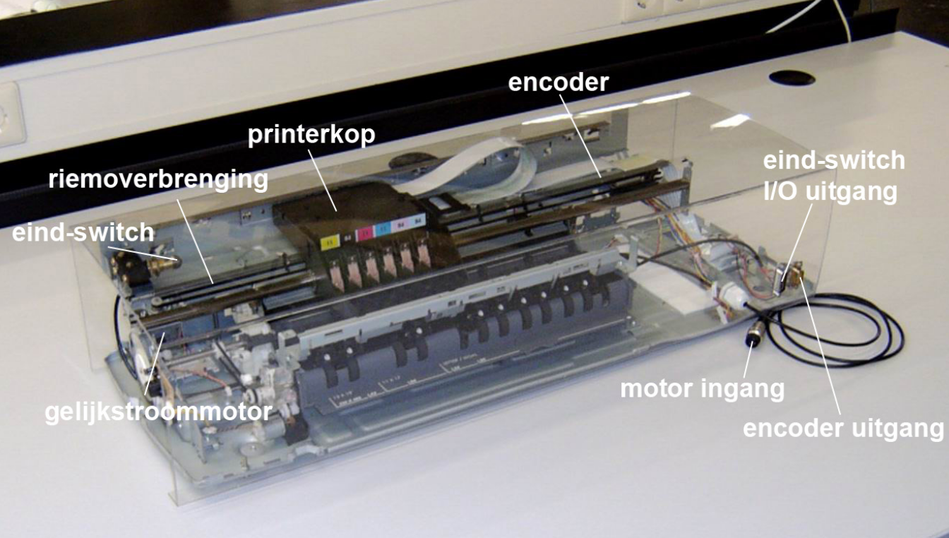
The case is a stripped A3 HP printer, see Figure 1. The required hardware for the experimental set-up is included in Table 1. You have to take your own notebook to do experiments.
Required hardware
- Notebook with E/box image installed
- Experimental HP printer setup (see Figure 1) including cables
- Amplifier including BNC cable
Table 1
The print head is driven by a DC motor using a belt transmission. The position of the print head is measured by means of a linear encoder. The optical encoder sensor is mounted in the printhead. On the left side an end-switch is mounted that is used to position the printhead initialization. Using the E/box it is possible to perform real-time experiments on the printer, i.e. measuring and sending signals in real-time. The amplifier provides the necessary current gain of the control signal transmitted from the E/box to the motor is controlled.
The cables of the hardware should be mounted as shown in Table 2 below. Furthermore, the amplifier and E/boxof supply cables must be provided. CAUTION: NEVER turn the amplifier on (ON) before a control signal is defined by the ectarget software (see # Start-up and experiments). A crash of the printer may result. On some older amps is still 0 to 2.5 V instead of + / - 2.5 V. This is incorrect, all amplifiers have a range of + / - 2.5 V.
| I/O Printer | I/O Amplifier | I/O E/box | I/O Notebook |
|---|---|---|---|
| Motor input | LOAD | ||
| Encoder output | Encoder 1 | ||
| End-switch I/O | DIGITAL I/O | ||
| +/ − 2, 5 V in | Analog out 1 | ||
| Ethernet port | Ethernet port |
Table 2
