Sensor Fusion: Difference between revisions
No edit summary |
(→Method) |
||
| Line 15: | Line 15: | ||
<p>In which</p> | <p>In which</p> | ||
<math> \ \ \ \ \ \ \ | <math> \ \ \ \ \ \ \ x=\begin{pmatrix} | ||
\theta \\ | \theta \\ | ||
| Line 21: | Line 21: | ||
\end{pmatrix}</math> | \end{pmatrix}</math> | ||
<math> \ \ \ \ \ \ \ | <math> \ \ \ \ \ \ \ z=\begin{pmatrix} | ||
\theta_1 \\ | \theta_1 \\ | ||
| Line 27: | Line 27: | ||
\end{pmatrix}</math> | \end{pmatrix}</math> | ||
\\ | \\ | ||
<p>and F is:</p> | <p>and F is:</p> | ||
<math> \ \ \ \ \ \ \ F=\begin{pmatrix} | <math> \ \ \ \ \ \ \ F=\begin{pmatrix} | ||
| Line 33: | Line 33: | ||
1 & T \\ | 1 & T \\ | ||
0 & 1 | 0 & 1 | ||
\end{pmatrix}</math> | \end{pmatrix}</math> | ||
<p>T is the sampling time. u(k) is controller input in moment k. θ1 is data coming from magneto meter and (θ1) ̇ is data coming from Gyroscope. </p> | <p>T is the sampling time. u(k) is controller input in moment k. θ1 is data coming from magneto meter and (θ1) ̇ is data coming from Gyroscope. </p> | ||
[[File:SA.jpg]] | |||
== Implementation == | == Implementation == | ||
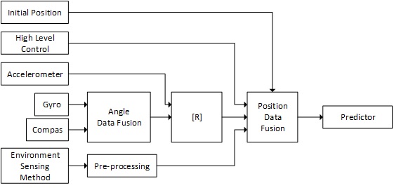
The system architecture of the data fusion block is as below. The data fusion blocks for position are basically Kalman filters with measurement inputs from different kinds of sensors. The positioning sensor fusion also has an input from control unite. | The system architecture of the data fusion block is as below. The data fusion blocks for position are basically Kalman filters with measurement inputs from different kinds of sensors. The positioning sensor fusion also has an input from control unite. | ||
Revision as of 06:43, 13 April 2016
Purpose
In the designed system there are some environment sensing methods that give the same information about the environment. It can be proven that measurement updates can increase accuracy of a probabilistic function. As an example, Localization block can use UltraWide band and acceleration sensors to localize the position of drone. This data fusion is desirable because the UltraWide band system has a high accuracy but low response time, and acceleration sensors have lower accuracy but a higher response time. The other system that can benefit from sensor fusion is the psi angel block. The psi angel is needed for drone motion control and also for other detection blocks. The data of the psi angle are coming from the drone’s magneto meter and gyroscope. The magneto meter gives the psi angle with a rather high error. The gyroscope gives the derivation of the psi angle. The data provided by the gyroscope has a high accuracy but because it is derivation of psi angle the uncertainty increases by time. Sensor fusion can be used in this case to correct data coming from both sensors.
Method
There are several sensor fusion methods available. We tested Bayesian algorithm and Kalman filter algorithm. The Kalman filter appeared to be more robust and gave better results. It is important to mention that the Kalman filter practically does the optimization in the innovation state, when it compares the output prediction to the sensor measurements. For the angle data fusion the x(k) in Kalman filter is:
[math]\displaystyle{ x(k│k-1)=F(k)x(k-1│k-1)+G(k)u(k) }[/math]
In which
[math]\displaystyle{ \ \ \ \ \ \ \ x=\begin{pmatrix} \theta \\ \theta' \end{pmatrix} }[/math]
[math]\displaystyle{ \ \ \ \ \ \ \ z=\begin{pmatrix} \theta_1 \\ \theta'_1 \end{pmatrix} }[/math] \\
and F is:
[math]\displaystyle{ \ \ \ \ \ \ \ F=\begin{pmatrix} 1 & T \\ 0 & 1 \end{pmatrix} }[/math]
T is the sampling time. u(k) is controller input in moment k. θ1 is data coming from magneto meter and (θ1) ̇ is data coming from Gyroscope.
Implementation
The system architecture of the data fusion block is as below. The data fusion blocks for position are basically Kalman filters with measurement inputs from different kinds of sensors. The positioning sensor fusion also has an input from control unite.
