Line Detection: Difference between revisions
No edit summary |
|||
| (12 intermediate revisions by the same user not shown) | |||
| Line 6: | Line 6: | ||
<p> | <p> | ||
Similar to the circular shape matching described in the ball detection approach, here the Hough transform is used to detect lines. Before doing so, several steps must be performed:.</p> | Similar to the circular shape matching described in the ball detection approach, here the [https://en.wikipedia.org/wiki/Hough_transform Hough transform] is used to detect lines. Before doing so, several steps must be performed:.</p> | ||
<p> 1. Undistort image to get straight lines (In case a wide/fisheye camera is used)</p> | <p> 1. Undistort image to get straight lines (In case a wide/fisheye camera is used)</p> | ||
| Line 15: | Line 14: | ||
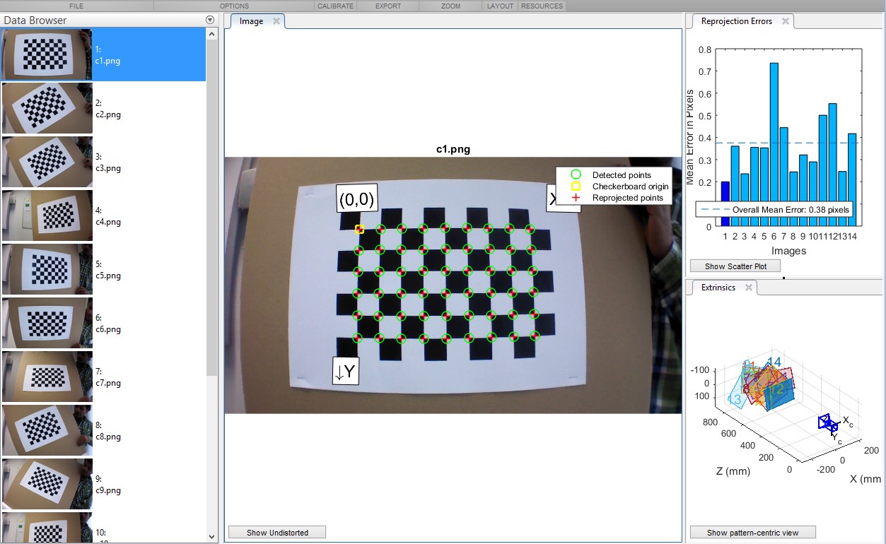
[[File:Camera calibration app.jpg|thumb|right|upright=1.5|Camera Calibration App. Source: MATLAB]] | [[File:Camera calibration app.jpg|thumb|right|upright=1.5|Camera Calibration App. Source: MATLAB]] | ||
===Undistort image (If applicable)=== | |||
<p>In order to undistort the image to get the real perspective you should get the transformation matrix between the frame and the real world. Thus, the camera parameters should be known. If this are not known you can always calibrate the camera based on the output of a specific object with several frames from different perspectives. The commonly used technique is to use a calibration template with black and white squares of the same length disposed alternatively like a ‘chessboard’. Then, you will only need to know the real size of the squares to calibrate it. In this project, the ‘Camera Calibration’ App from MATLAB was used to get the camera parameters.</p> | <p>In order to undistort the image to get the real perspective you should get the transformation matrix between the frame and the real world. Thus, the camera parameters should be known. If this are not known you can always calibrate the camera based on the output of a specific object with several frames from different perspectives. The commonly used technique is to use a calibration template with black and white squares of the same length disposed alternatively like a ‘chessboard’. Then, you will only need to know the real size of the squares to calibrate it. In this project, the ‘Camera Calibration’ App from MATLAB was used to get the camera parameters.</p> | ||
[[File:Undistorted matlab.jpg|thumb|right|upright=2|Original frame (left). Result after undistorting the image (right)]] | [[File:Undistorted matlab.jpg|thumb|right|upright=2|Original frame (left). Result after undistorting the image (right)]] | ||
<p> | <p> | ||
The result after applying the correct transformation matrix should be getting the real straight lines within the frame:</p> | The result after applying the correct transformation matrix should be getting the real straight lines within the frame:</p> | ||
</ | |||
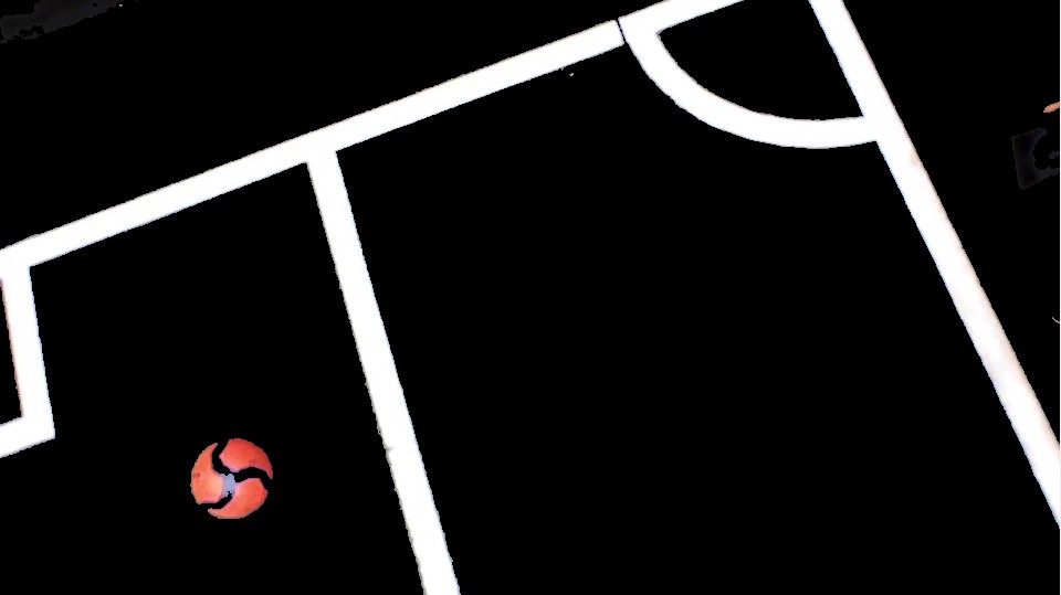
[[File:Detection masking undistort.jpg|thumb|right|upright=1.25|Result after applying Red Ball & Line mask + undistorting]] | |||
===Apply a color mask to get only the lines on the frame=== | |||
<p>See [[Ball Detection]] color filtering section for a detailed explanation.</p> | |||
===Line Detection=== | |||
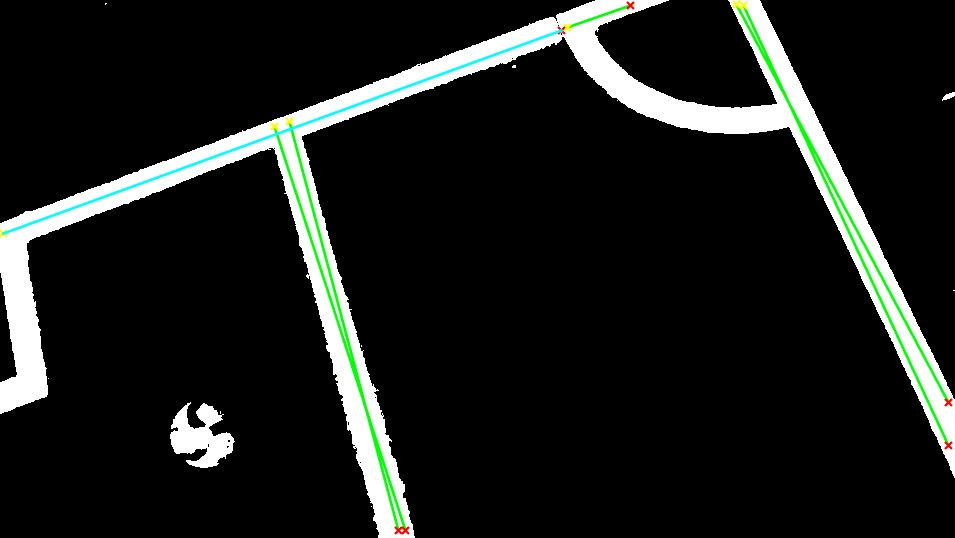
<p>In the last step, the [https://en.wikipedia.org/wiki/Hough_transform Hough transform] is used to get lines candidates after some pre-processing has been done, e.g. RGB to black and white conversion, thinning, etc.</p> | |||
<p>The main concern here is to be able to select the correct lines to enable the refereeing. The selecting process used in this project involves the following steps:</p> | |||
* Clustering lines with similar ‘rho’ and ‘theta’ (For definitions of these parameters see [http://mathworks.com/help/images/ref/hough.html Hough transform MATLAB]). The real number of lines detected will be the number of clusters identified under a pre-defined ‘rho’ and ‘theta’ threshold. | |||
* Selecting the longest line segment within each cluster detected as a representative of that line. | |||
* Filtering the real outer lines out of all the candidates by comparing them to the information provided by the [[Field Line predictor]]. | |||
[[File:Line detection hough.jpg|thumb|right|upright=1.25|Line detection performed in the pre-processed frame]] | |||
Thus, in the end, we will compare the ‘rho’ and ‘theta’ of the candidate lines provided by the [https://en.wikipedia.org/wiki/Hough_transform Hough transform] with the ‘rho’ and ‘theta’ estimation of the outer lines provided by the [[Field Line predictor]] that takes into account the drone/camera position, FOV, height and psi/yaw angle. | |||
One condition to enable [[Refereeeing Out of Pitch]] is to have a positive matching between the lines detected and the outer lines references provided by the [[Field Line predictor]]. | |||
==Line detection output== | |||
<p> | |||
The Line Detection sub-task outputs the best line candidates detected.</p> | |||
==Use in refereeing== | |||
<p> | |||
One condition to enable [[Refereeing Out of Pitch]] is to have detected and matched the lines detected with the references provided by the [[Field Line predictor]].</p> | |||
Latest revision as of 11:06, 1 April 2016
Design Choice
The purpose of detecting lines is to identify the lines that enclose the field and be able to referee an out of pitch ball or a goal scored. Along with ball detection, a vision based method was required to gain accuracy while refereeing without using invasive methods on the ball or the pitch.
Methodology
Similar to the circular shape matching described in the ball detection approach, here the Hough transform is used to detect lines. Before doing so, several steps must be performed:.
1. Undistort image to get straight lines (In case a wide/fisheye camera is used)
2. Apply a color mask to get only the lines on the frame
3. Line Detection

Undistort image (If applicable)
In order to undistort the image to get the real perspective you should get the transformation matrix between the frame and the real world. Thus, the camera parameters should be known. If this are not known you can always calibrate the camera based on the output of a specific object with several frames from different perspectives. The commonly used technique is to use a calibration template with black and white squares of the same length disposed alternatively like a ‘chessboard’. Then, you will only need to know the real size of the squares to calibrate it. In this project, the ‘Camera Calibration’ App from MATLAB was used to get the camera parameters.

The result after applying the correct transformation matrix should be getting the real straight lines within the frame:

Apply a color mask to get only the lines on the frame
See Ball Detection color filtering section for a detailed explanation.
Line Detection
In the last step, the Hough transform is used to get lines candidates after some pre-processing has been done, e.g. RGB to black and white conversion, thinning, etc.
The main concern here is to be able to select the correct lines to enable the refereeing. The selecting process used in this project involves the following steps:
- Clustering lines with similar ‘rho’ and ‘theta’ (For definitions of these parameters see Hough transform MATLAB). The real number of lines detected will be the number of clusters identified under a pre-defined ‘rho’ and ‘theta’ threshold.
- Selecting the longest line segment within each cluster detected as a representative of that line.
- Filtering the real outer lines out of all the candidates by comparing them to the information provided by the Field Line predictor.

Thus, in the end, we will compare the ‘rho’ and ‘theta’ of the candidate lines provided by the Hough transform with the ‘rho’ and ‘theta’ estimation of the outer lines provided by the Field Line predictor that takes into account the drone/camera position, FOV, height and psi/yaw angle. One condition to enable Refereeeing Out of Pitch is to have a positive matching between the lines detected and the outer lines references provided by the Field Line predictor.
Line detection output
The Line Detection sub-task outputs the best line candidates detected.
Use in refereeing
One condition to enable Refereeing Out of Pitch is to have detected and matched the lines detected with the references provided by the Field Line predictor.