Embedded Motion Control 2012 Group 3: Difference between revisions
(→Week 4) |
(→Week 4) |
||
| Line 129: | Line 129: | ||
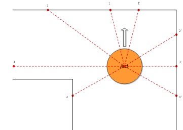
The robot will use the data from the odometry, laser and camera to navigate through the maze. The raw laser data processed and few relevant points will be extracted from it. The noise will be filtered by averaging the data(after applying trigonometric transformation) from few points around the desired one. The relevant points are shown on the next figure: | The robot will use the data from the odometry, laser and camera to navigate through the maze. The raw laser data processed and few relevant points will be extracted from it. The noise will be filtered by averaging the data(after applying trigonometric transformation) from few points around the desired one. The relevant points are shown on the next figure: | ||
[[File: | [[File:Example2.jpg]] | ||
The points in front of the robot will be used for preventing it from hitting the walls of the maze. The two sideways points(2 and 2’) will be used to keep the robot moving straight, by comparing them. 3 and 3’ will be used for detecting of a junction and they with 4 and 4’ will be used to determine where the center of the junction is. | |||
After the junction is detected its type will be sent to the process that builds the map. The map will be array of structures (or classes) that keep the coordinates and orientation of every junction, its type and the exits that have been taken before and that the robot has come from. | |||
The position will be used in building the map, but the map also will be used in readjusting the current position if the robot reaches a junction it has been before. The odometry will be reset on every junction and the value that will be taken into account will be the √(x^2+y^2 ) as this determines the total distance traveled by the robot after the junction. Depending on the direction that the robot goes after the junction this value will be added to x or y coordinates. If large rotational correction is applied after a junction this will mean that the corner is not exactly 90 degrees and will be taken into account for the coordinate computation. | |||
The exact movement strategy is yet to be determined. It will stop the robot at every junction, determine the direction, and send a rotational command, which will be executed by the movement control. The control for keeping the robot straight will operate only if the robot is not at a junction and is not currently rotating. | |||
We consider that taking right at every junction, the robot will be able to go out of the maze and for the case when we have only a left turn and front path the robot will go forward. | |||
There will be considered 5 types of junctions: The X type (1), T type (2), left (3) and right (4) type, and dead-end (5). These possibilities are depicted in the figures below. | |||
Revision as of 20:52, 19 May 2012
Contact Info
| Name | Number | E-mail address |
|---|---|---|
| X. Luo (Royce) | 0787321 | x.luo@student.tue.nl |
| A.I. Pustianu (Alexandru) | 0788040 | a.i,pustianu@student.tue.nl |
| T.L. Balyovski (Tsvetan) | 0785780 | t.balyovski@student.tue.nl |
| R.V Bobiti (Ruxandra) | 0785835 | r.v.bobiti@student.tue.nl |
| G.C Rascanu (George) | 0788035 | g.c.rascanu@student.tue.nl |
GOAL
Win the competition!
HOW ?
Good planning and team work
Week 1 + Week 2
1. Installing and testing software tools
- Linux Ubuntu
- ROS
- Eclipse
- Jazz simulator
Remark:
Due to incompatibilities with Lenovo W520 (wireless doesn’t work), Ubuntu (10.04) did not work and other versions were tried and tested to work properly. All the software was installed for all members of the group.
2. Discussion about the robot operation
Targeting units:
- Maze mapping
- Moving Forward
- Steering
- Decision making
Moving forward and steering
Make choice between what sensors for straight line and what sensors for turning left/right.
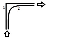
Case 1 – Safer, but slower
Case 2- Faster, but more challenging
Time difference between these 2 cases is small or not? According to the simulations we will decide between Case 1 and Case 2.
Backward movement!
Because the target is to get out of the maze as fast as possible this kind of movement will be considered as a safety precaution at the end of the project whether is time or not.
Speed
As mentioned earlier the main requirement is as fast possible, hence take the maximum speed (~ 1 m/s).
Sensors
Web cam -> Identify arrows on the walls by color and shape.
Laser -> Map of the world (range ~< 6 m).
Encoders -> Mounted on each wheel -> used for odometry (estimates change in position over time). How many pulses per revolution?
3. Making planning of the work process
All the team members start reading C++ and ROS tutorials given on the wiki page of the course.
4. Had the first meeting with the tutor.
Week 3
After our meeting, the lecture regarding Tasks of Chapter 5 was split among our team members:
- Introduction + Task definition – Bobiti Ruxandra
- Task states and scheduling – Luo Royce
- Typical task operation - Pustianu Alexandru
- Typical task structure – Rascanu George
- Tasks in ROS - Balyovski Tsvetan
The link for the presentation is given here: http://cstwiki.wtb.tue.nl/images/Tasks.pdf
- Problem with RViz was fixed and solution was posted in FAQ.
- Investigation of the navigation stacks and possibility to create map of the environment. The link for relevant messages is given here.
- Thinking and discussing about smart navigation.
The come up ideas were:
We should save in a buffer the route were the robot went and not go twice through same place. For turning left or right, for case 2 presented in Week 1 and 2, we want to use so cubic or quitting splines. An example of the idea is given in the paper "Task-Space Trajectories via Cubic Spline Optimization" - J. Zico Kolter and Andrew Y. Ng
Week 4
This week was focused mainly on the software structure. The structure we come up was developed after discussing multiple options in such a way to make it simple so that every one can write his own part of the code and no one confuse what is there.In other words: make simple as possible.
Software structure
The structure of the control software is depicted in Figure 1:
The robot will use the data from the odometry, laser and camera to navigate through the maze. The raw laser data processed and few relevant points will be extracted from it. The noise will be filtered by averaging the data(after applying trigonometric transformation) from few points around the desired one. The relevant points are shown on the next figure:
The points in front of the robot will be used for preventing it from hitting the walls of the maze. The two sideways points(2 and 2’) will be used to keep the robot moving straight, by comparing them. 3 and 3’ will be used for detecting of a junction and they with 4 and 4’ will be used to determine where the center of the junction is.
After the junction is detected its type will be sent to the process that builds the map. The map will be array of structures (or classes) that keep the coordinates and orientation of every junction, its type and the exits that have been taken before and that the robot has come from.
The position will be used in building the map, but the map also will be used in readjusting the current position if the robot reaches a junction it has been before. The odometry will be reset on every junction and the value that will be taken into account will be the √(x^2+y^2 ) as this determines the total distance traveled by the robot after the junction. Depending on the direction that the robot goes after the junction this value will be added to x or y coordinates. If large rotational correction is applied after a junction this will mean that the corner is not exactly 90 degrees and will be taken into account for the coordinate computation.
The exact movement strategy is yet to be determined. It will stop the robot at every junction, determine the direction, and send a rotational command, which will be executed by the movement control. The control for keeping the robot straight will operate only if the robot is not at a junction and is not currently rotating.
We consider that taking right at every junction, the robot will be able to go out of the maze and for the case when we have only a left turn and front path the robot will go forward. There will be considered 5 types of junctions: The X type (1), T type (2), left (3) and right (4) type, and dead-end (5). These possibilities are depicted in the figures below.


